1. INTRODUCTION AND SAFETY PRECAUTIONS
1.1 Introduction
Dear Customer,
Congratulations on purchasing Mahindra XUV500. Your vehicle has been designed to provide years of safe and dependable service, as long as it is used and maintained in accordance with the instructions provided in this manual.
All persons who will use and/or maintain this vehicle must read, understand and follow all warnings and instructions provided in this manual. This Owner's Manual should be considered an integral part of the vehicle and should remain with the vehicle. However, nothing in this manual, and none of the safety devices installed in the vehicle, are a substitute for careful operation and common sense. Always make sure that your vehicle is in optimum working order, and take note of the road and weather conditions under which you are using your vehicle.
If you have any questions concerning the proper use or maintenance of your vehicle, please call your Authorized Mahindra Dealer. A list of dealers can be found in the Dealer Directory Supplement.
Alternatively you can contact Mahindra at,
- 1800-209-6006 (Toll free)
- customercare@mahindra.com
We extend our best wishes for safe and pleasurable motoring.
Sincerely,
MAHINDRA & MAHINDRA LTD.
1.2 Preliminary Servicing and Summary Data
- For all issues concerning the vehicle and for any need for spare parts, contact only the Authorized Mahindra network
- We recommend you always use genuine Mahindra spare parts when performing repairs on the vehicle
- We suggest that you record the vehicle data in the Service Coupon Booklet for future references
1.3 Safety Symbols
Carefully read, understand and follow the safety symbols/ instructions given in this manual.
To emphasize information and procedures regarding safety, use, maintenance, etc., the following symbols are used throughout the manual.
1.4 General Safety Information and Instructions
Failure to follow the warnings and instructions provided in this manual could result in failure of the vehicle, an accident and/or serious personal injury.
- Carefully read, understand and follow the warnings and instructions given in this manual. This manual is an essential part of the product. Keep it in a safe place for future reference
- Please note that throughout this manual, reference is made that “an accident” could occur. An accident could cause you or a bystander to sustain severe personal injury, or result in property damage
- Never use a mobile phone, personal music device or pager while driving. This may take your focus off the road and lead to accidents
- Please be advised that many service and repair tasks require specialized knowledge, tools and experience. General mechanical aptitude may not be sufficient to properly service or repair your vehicle. If you have any doubt whatsoever regarding your ability to properly service or repair your vehicle, please contact your Authorized Mahindra Dealer or a qualified mechanic
- A person with a pacemaker should never contact the engine control unit or its cables to injectors, as this system carries high voltage which may adversely affect the functioning of the pacemaker
- Inspect the seat belt system periodically, checking for cuts, frays or wear in the seat belt webbing, or loose buckles, retractors, anchors or other loose parts. Damaged parts must be replaced immediately
- Always start and operate the engine in a well-ventilated area. If in an enclosed area, vent the exhaust to the outside. Do not modify or tamper with the exhaust system
- Examine tires for excessive tread wear and uneven wear patterns. Check for stones, nails, glass, or other objects lodged in the tread and check sidewalls for any cuts, cracks, or other signs of wear. Replace as necessary
- Always maintain the safety labels affixed to your vehicle in a good legible condition
- All signal lamps, buzzers, shields, guards and other protective safety devices must always remain in place and in good, proper working condition
- The life span of Mahindra products depend on many factors. Improper use, abuse or harsh use in general may compromise the integrity of the vehicle and significantly reduce its life span. The vehicle is also subject to wear over a period of time. Please have your vehicle regularly inspected by an Authorized Mahindra Dealer or a qualified mechanic. If the inspection reveals any damage or excessive wear, immediately replace or have the component serviced
- We recommend that you use only genuine parts supplied by Mahindra. The use of non-Mahindra parts will not be covered by warranty
- The vehicle can be used only as a passenger vehicle. Any other use is improper, and may result in voiding the warranty
- Never crawl under or be in close proximity to the vehicle when it is lifted off the ground (by a jack), unless the vehicle is properly supported with jack stands, wheel chocks and other appropriate safety devices
- Never attempt any repairs or adjustments to any component while the vehicle is in motion. Always switch off the engine, and wait for the engine to come to a complete stop before performing any repairs or adjustments
- The vehicle identification plates are the only legal identification reference, hence it is necessary to keep them in good condition. Never modify data on the plates or remove them. The customer is responsible for any possible tampering with the plates, which will immediately void the warranty
- Do not attempt sharp turns, abrupt maneuvers, or other unsafe driving actions that can cause loss of vehicle control. When the vehicle is fully loaded, drive at a slow speed, especially when turning. Note that the center of gravity of the vehicle increases as the vehicle is fully loaded on the roof carrier
1.5 To Owner’s of a Mahindra Vehicle
When first driving the vehicle after long periods of non-use, you may experience a temporary drive disturbance. This is a characteristic of the tires and should be no reason for concern. The condition should correct itself within 5-15 kms. of driving. If the disturbance persists, have the tires checked by an Authorized Mahindra Dealer.
If you have any questions concerning the proper use or maintenance of your vehicle, please call your Authorized Mahindra Dealer. A list of dealers can be found in the Dealer Directory Supplement or on the Internet.
Alternatively you can contact Mahindra on 1800-209-6006 / customercare@mahindra.com.
Your driving ability can be seriously impaired by alcohol even if the blood alcohol level is far below the legal minimum. Drunken driving is one of the most frequent causes of accidents.
Never drink and drive. Drinking and driving will lead to an accident resulting in serious personal injury.
Your driving ability can be seriously impaired through the use of prescription or non-prescription drugs or medication (even cough syrup). If you are taking any sort of drug or medication, be sure that it will not affect your driving ability.
Use of electrical devices such as mobile phones, computers, portable radios or other by the driver while driving is dangerous. Dialing a number on a mobile phone while driving also ties up the driver's hands. Use of these services will cause the driver to be distracted and may lead to a serious accident. If a passenger is unable to use the device, pull off the right-of way to a safe area before use. If use of a mobile phone is necessary despite this warning, use a hands free system to at least leave the hands free to drive the vehicle. Never use a mobile phone or other electrical devices while the vehicle is moving.
Please comply with the legal regulations concerning the use of communication equipment in vehicles in your country.
When you are driving over long distances, follow these tips so that you have a safe journey;
- Lack of sleep or fatigue may impact your ability to drive safely.
- Exercise your eyes by shifting the focus of your eyes to different parts of the road.
- Use stimulating beverages such as coffee or tea.
- Relax and stay calm.
Every one of us should play our part in protecting our environment. Judicious vehicle usage and disposing hazardous waste (including cleaning and lubrication fluids) are important steps towards this initiative.
Mahindra vehicles confirm to existing emission norms (standards). Adhering to the periodical maintenance schedule and using Mahindra genuine parts will help retain emission performance of the vehicle and is a pre-requisite to emissions warranty coverage.
1.6 Perchlorate Material
Certain components of this vehicle such as seat belt pre-tensioners and button cell batteries may contain perchlorate material. Special handling may be required for service or vehicle end-of-life disposal.
1.7 Running-in
Driving smoothly during first 1000 kms. will help to prevent premature failures and abnormal system wear improving the life of drivetrain and vehicle components.
A new engine may consume more oil during the first 1000 kms. of running. This should be considered as a normal part of break-in and not interpreted as any problem with the engine.
1.8 Protection from Electronics
To ensure optimum vehicle performance and passenger safety, your Mahindra vehicle is equipped with sophisticated modern electronics and controls. Do not install any communication devices, electronic gadgets or radar detection devices, without express written consent from Mahindra.
An improperly installed/adjusted two-way radio can adversely affect electronic systems.
1.9 Mahindra Genuine Parts
Mahindra uses high quality parts for building vehicles.
In the event that any parts need replacement, we recommend that you use only Mahindra genuine parts.
Non-Mahindra parts may harm vehicle performance and will not be covered by your Mahindra warranty.
To avoid counterfeit parts and to protect our brand image, Mahindra genuine parts are packed in a branded carton. Look for the “Mahindra Genuine Parts” logo.
Any unauthorized modifications or alterations to this vehicle or failure to use appropriate specification and quality spare parts could seriously affect vehicle road worthiness and safety leading to an accident, resulting in serious injury.
1.10 Mahindra Genuine Accessories
A wide selection of quality accessories is available through your authorized Mahindra dealership. These accessories have been specifically engineered to allow you to personalize your vehicle to suit your requirements and compliment its style and aerodynamic appearance.
Each accessory is made from high quality materials and meets Mahindra's rigid engineering and safety specifications. Every Mahindra accessory installed according to the Mahindra installation provisions comes with the respective accessory warranty.
Consult your Mahindra authorized dealer for detailed information about accessories available for your specific model variant.
- When adding accessories, equipment, passengers and luggage to your vehicle, do not exceed the total weight capacity of the vehicle or of the front and rear axle. Consult Mahindra authorized dealer for specific weight information.
- Mobile communications systems such as two way radios, telephones and theft alarms that are equipped with radio transmitters and installed in your vehicle should comply with the local regulations and should be installed only by a your Mahindra authorized dealer.
1.11 Roadside Assistance
Mahindra Roadside Assistance Program deploys fully trained technical assistance in the event of any breakdown. Roadside Assistance Program is free of cost during the standard warranty period of the vehicle.
Calls to the toll-free (1800-102-7006) Roadside Assistance Number will be answered by Mahindra Customer Care representatives 24 hours a day and 365 days a year. For additional information about this assistance, discuss with your authorized Mahindra dealer who will be glad to provide information on your request.
1.12 Vehicle Identification Number (VIN):
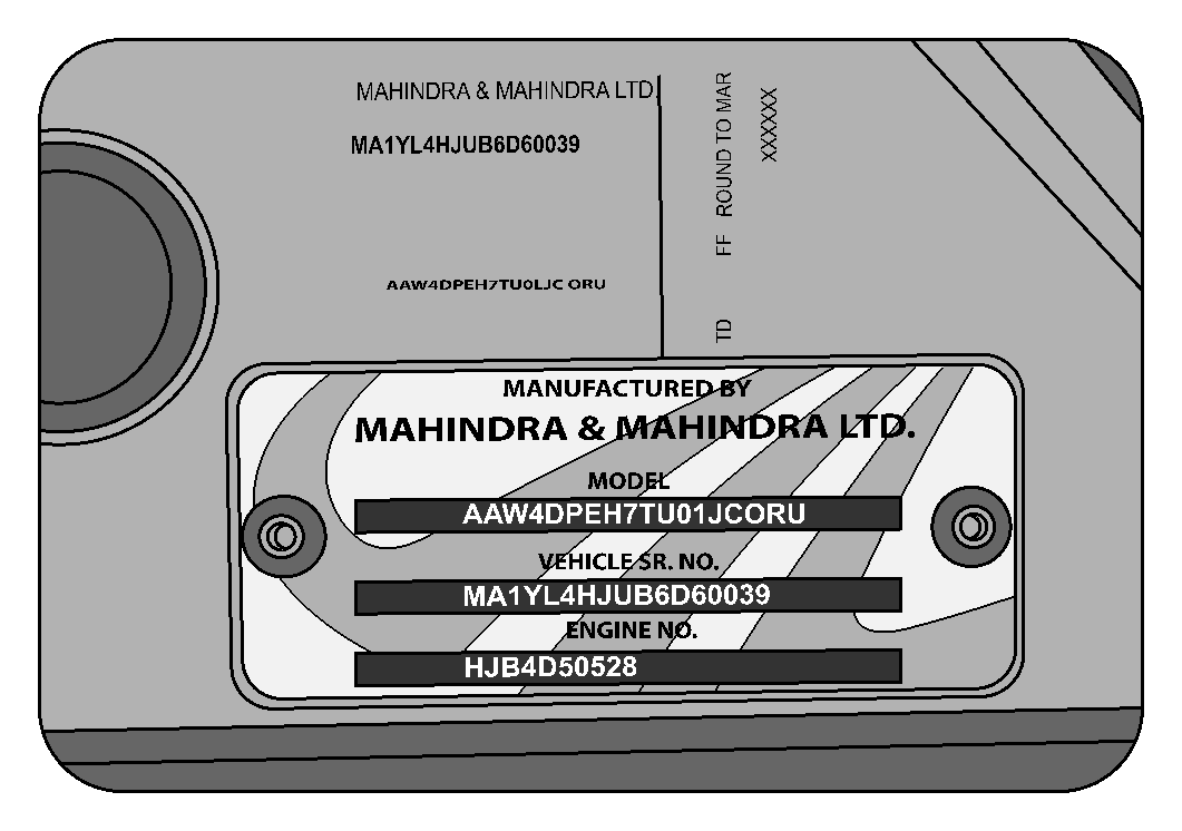
Vehicle Identification Number (VIN) is the legal identity of your vehicle. The vehicle identification number is stamped on the VIN plate riveted on to the bottom of the B-Pillar on the driver side.
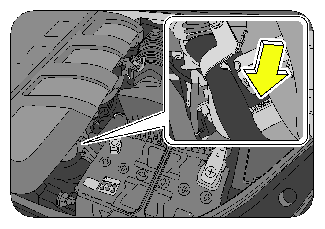
1.13 Engine Number
The engine number is punched on the bottom of the intake manifold near the starter motor.
1.14 Vehicle Safety
When leaving your vehicle unoccupied;
- Always remove the ignition key even when you park the vehicle
- Close all the windows completely and lock all the doors
- If you have an alarm, enable/activate it even if it is for a short period
- Do not leave any valuables in your vehicle. If you must leave something in your vehicle, hide them and securely lock all the doors
- Do not leave the original vehicle documents or spare key in your vehicle. In the unfortunate event of your vehicle being stolen the documents will only help a thief sell the vehicle more easily
2 GENERAL
2.1 Feature Matrix
In view of the policy of continuously improving our products, we reserve the right to alter specifications or designs without prior notice and without liability/obligation. Illustrations do not show the vehicle in the standard form. Please be aware that this manual may apply to various models/variants . As a result you may find some explanations for equipment not installed on your vehicle. All the information, illustration, and specifications in this manual are based on the latest product information available at the time of publication.
We recommend you to contact the nearest Mahindra dealer for latest features applicable to your vehicle.
| FEATURE | W6 | W8 / W8 AWD |
|---|---|---|
| Technology | ||
| Micro Hybrid Technology | ✓ | ✓ |
| Static-Bending Projection Head Lamps with LED Parking Lights | ✓ | ✓ |
| 6" Color Touchscreen Infotainment Display | ✓ | |
| 6" Monochrome Infotainment Display | ✓ | |
| GPS Navigation with Touchscreen and Audio Support | ✓ | |
| Integrated Music System with CD/MP3 I-Pod & USB Connectivity | ✓ | ✓ |
| 4 Door Speakers with 2 Tweeters | ✓ | ✓ |
| DVD Player | ✓ | |
| DIS in-built in Infotainment System | ✓ | ✓ |
| Tyretronics | ✓ | |
| lntellipark | ✓ | ✓ |
| Smart Rain Sensing Wipers | ✓ | ✓ |
| Intelligent Light Sensing Head Lamps | ✓ | ✓ |
| Digital Immobilizer | ✓ | ✓ |
| Glass Embedded Antenna | ✓ | ✓ |
| Safety | ||
| Dual Airbag’s (Driver + Passenger) | ✓ | ✓ |
| Side & Curtain Airbag’s | ✓ | |
| ABS with Electronic Brake-force Distribution (EBD) | ✓ | ✓ |
| Electronic Stability Program (ESP) with Rollover Mitigation | ✓ | |
| Hill Hold and Hill Descent Control | ✓ | |
| Side Impact Beams | ✓ | ✓ |
| Crumple Zones for Crash Protection | ✓ | ✓ |
| Disc Brakes on all Wheels | ✓ | ✓ |
| Style | ||
| Alloy Wheels | ✓ | |
| Full Wheel Caps | ✓ | |
| Twin Exhausts | ✓ | ✓ |
| Front and Rear Fog Lamps | ✓ | ✓ |
| Roof Rails | ✓ | ✓ |
| Dual Tone Interiors | ✓ | ✓ |
| Comfort | ||
| Tilt Power Steering | ✓ | ✓ |
| Telescopic Steering | ✓ | |
| Fully Automatic Temperature Control (FATC) & Dual HVAC | ✓ | ✓ |
| Premium Fabric Seats | ✓ | |
| Leather Upholstery | ✓ | |
| Power-adjustable ORVM’s | ✓ | ✓ |
| Power-foldable ORVM’s | ✓ | |
| Centre Armrest & Cup Holders in 2 nd row | ✓ | ✓ |
| 8-way Adjustable Seats including Height and Lumbar Adjust (Driver's Side) | ✓ | ✓ |
| Height Adjustable Seat Belts (Front Row) | ✓ | ✓ |
| Convenience | ||
| Cruise, Audio, Phone Controls & Voice Command Switches on Steering | ✓ | ✓ |
| Power Windows with Driver Side Express Down | ✓ | ✓ |
| Remote Tailgate Opening | ✓ | ✓ |
| Flip-key with Remote Central Locking | ✓ | ✓ |
| Reading Lamps in all 3 Rows | ✓ | ✓ |
| Conversation Mirror | ✓ | ✓ |
| Tinted Solar-Reflecting Glass | ✓ | ✓ |
| Mobile Charging Points (all 3 rows) | ✓ | ✓ |
| Rear Wash and Wipe | ✓ | ✓ |
| Rear De-mister | ✓ | ✓ |
| Follow-me-Home Head Lamps | ✓ | ✓ |
| Lead-me-to-Vehicle Lamps | ✓ | ✓ |
| Illuminated Key Rings | ✓ | ✓ |
| Puddle Lamps | ✓ | ✓ |
| Entry Assist Lamp | ✓ | ✓ |
| Door Ajar Lamps | ✓ | ✓ |
| Camping Lamp | ✓ | ✓ |
| Remote Fuel Lid Opener (Electrically Operated) | ✓ | ✓ |
| Umbrella Holder | ✓ | ✓ |
| Glove Box with Laptop Holder | ✓ | ✓ |
2.2 Lubricants and Capacities
| System | Lubricant | Capacity | Specification | Remarks |
|---|---|---|---|---|
| Engine Oil | MAHINDRA "MAXIMILE FEO" NEW GENERATION GENUINE ENGINE OIL | 6.0 liters | Special Engine Fluid | For other than Maximile brand, the oil change interval has to be reduced to 10,000 km if the oil meets minimum of API CH-4 SAE 15W-40 specification |
| Engine Oil Filter | MAHINDRA "MAXIMILE UNIVERSE" GENUINE OIL FILTER | - | Recommend to use only the Genuine filter for better engine protection and lubricant life | |
| Engine Cooling | MAHINDRA "MAXIMILE ULTRA COOL" (READY TO USE COOLANT. NO NEED TO MIX WATER) | ~8.0 liters | Brand Specific. Don’t use other coolants / water for top up. In case of emergency, coolant meeting JIS K-2234 specification should be used (30% concentration diluted with distilled water) and coolant change period to be reduced to 30,000 km | |
| Transaxle Oil | MAHINDRA "MAXIMILE SYNTEC F2" NEW GENERATION GENUINE TRANSMISSION OIL | 3.0 liters | Special Manual Transmission Fluid | If Maximile GO Synchro 80W-90 is used, the oil change interval has to be reduced to 40,000 km. For other than Maximile brand, oil change interval to be reduced to 20000 km if oil meets minimum of API GL-4 SAE 80W-90 |
| Rear Axle Oil (AWD only) | MAHINDRA "MAXIMILE DO ELITE" | 0.7 liter | Special Axle Fluid | For other than Maximile brand, the oil change interval has to be reduced to 20,000 km if the oil meets minimum of API GL-5 SAE 80W-90 specification |
| Power Transfer Unit Oil (AWD) | MAHINDRA "MAXIMILE DO ELITE" | 0.8 liter | Special Axle Fluid | For other than Maximile brand, the oil change interval has to be reduced to 20,000 km if the oil meets minimum of API GL-5 SAE 80W-90 specification |
| Power Steering | SHELL "SPIRAX S3 ATF MD3" / CALTEX "TEXAMATIC 1888" | 0.75 liter | DEXRON III | Brand specific and no other brands recommended |
| Brake and Clutch | CASTROL "BRAKE FLUID DOT 4" / SHELL "CLUTCH & BRAKE FLUID DOT 4" | 1.0 liter | Brake Fluid Meeting SAE J1703; FMVSS No.116 DOT 4 or IS 8654 Type-2 Spec | |
| Refrigerant | R134a (AC Gas) |
Single AC | 520 ± 20 gms | - | |
| Dual AC | 720 ± 20 gms | - | |||
| FD46XG (Compressor Oil) | 150 ± 20 | - | |||
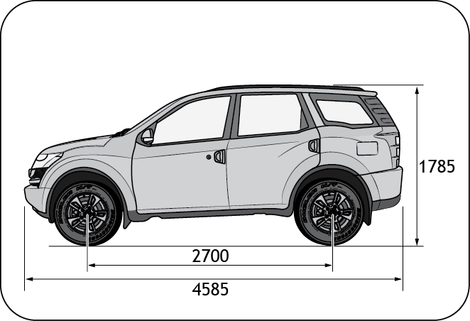
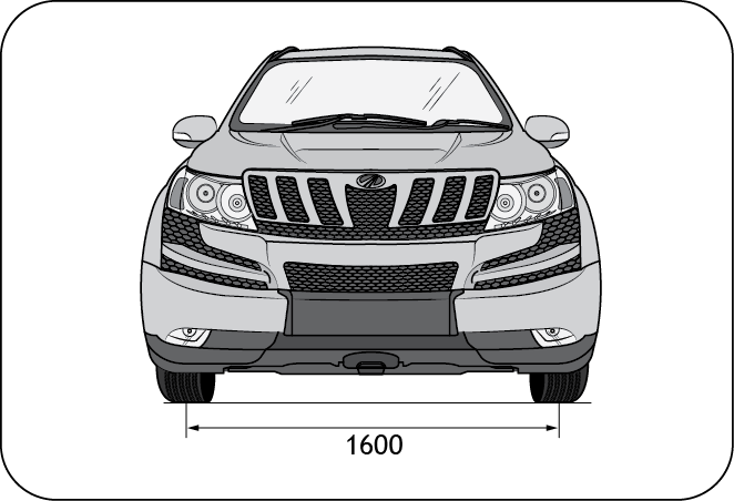
2.3 Dimensions
| DIMENSION & WEIGHTS | mm |
|---|---|
| Wheel Base | 2700 mm |
| Overall Length | 4585 mm |
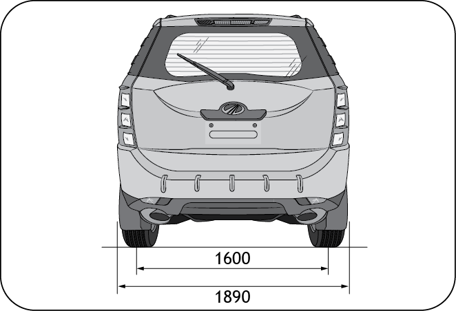
| Overall Width | 1890 mm |
| Overall Height | 1785 mm |
| Track Width (Front & Rear) | 1600 mm |
| Kerb Weight | 1785±15 (W6) 1860±15 (W8) |
| Maximum GVW | 2450 |
2.3.1 Front View
2.3.2 Rear View
2.3.3 Side View
2.4 Bulb Specification
| Lamp Bulb | Wattage | Bulb Type | No. of Bulbs per Vehicle |
|---|---|---|---|
| Head Lamp - High Beam | 12V 55W | H7 55W | 2 |
| Head Lamp - Low Beam | 12V 55W | H7 55W | 2 |
| Parking Lamps (Front) | 12V 5W | W5W | 2 |
| Turn Signal Lamp (Front) | 12V 21W | P21W | 2 |
| Static Bending Lamp | 12V 55W | H1 55W | 2 |
| Fog Lamp (Front) | 12V 35W | H8 35W | 2 |
| Stop Lamp | 12V 21W | P 21W | 2 |
| Turn Signal Lamp (Rear) | 12V 21W | PY 21W | 2 |
| Reverse Lamp | 12V 21W | P 21W | 2 |
| Parking Lamps (Rear) | 12V 5W | W5W | 6 |
| Side Marker Lamp (Rear) | 12V 5W | W5W | 2 |
| Fog Lamp (Rear) | 12V 21W | PR 21W | 2 |
2.5 Fuses and Relays
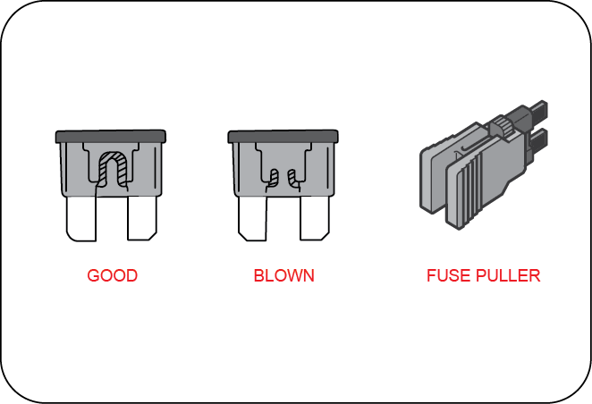
A fuse is the most common electric protection device. A fuse is placed in an electrical circuit, so that when current flow exceeds the rating of the fuse it blows off.
The element in the fuse melts, opening the circuit and preventing other components of the circuit from being damaged by the over current. The size of the metal fuse element determines the rating. Once a fuse blows off, it must be replaced with a new one.
Switch the ignition and all electrical equipment OFF before touching or attempting to change a fuse.
Fit replacement fuse with the same rating as the one you have removed.
You can identify a blown fuse by a break in the filament. All fuses except high current fuses are a push fit. A fuse puller should be used to remove the fuse from its position.
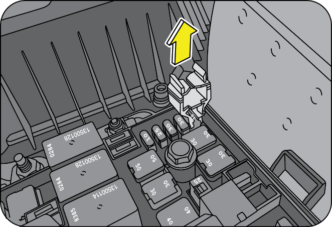
2.5.1 Engine Compartment Fuse Box
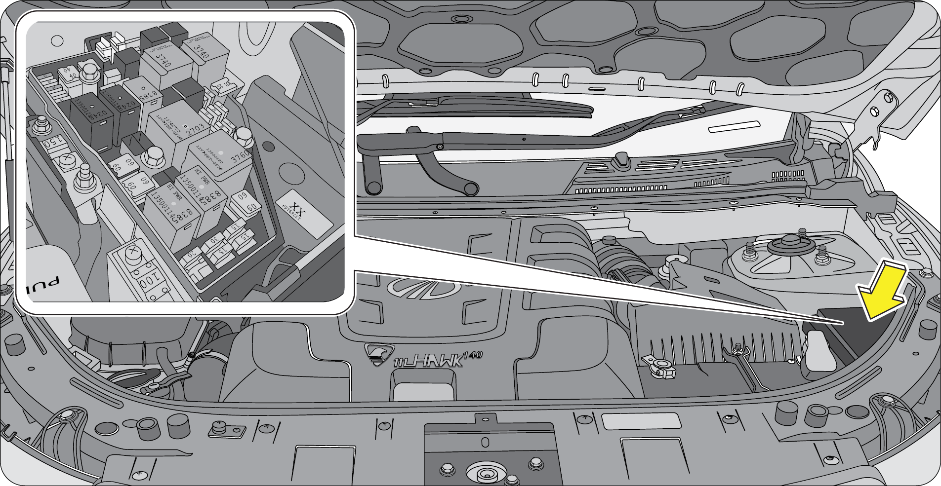
Engine compartment fuse box is located adjacent to vehicle battery. Release the lock to access the fuse box contents. Remove the fuse box cover by pressing the clips from both sides using both hands simultaneously. Spare fuses are provided in the fuse box for replacement of blown fuses. Ensure the correct rating fuse is replaced with the blown fuse.
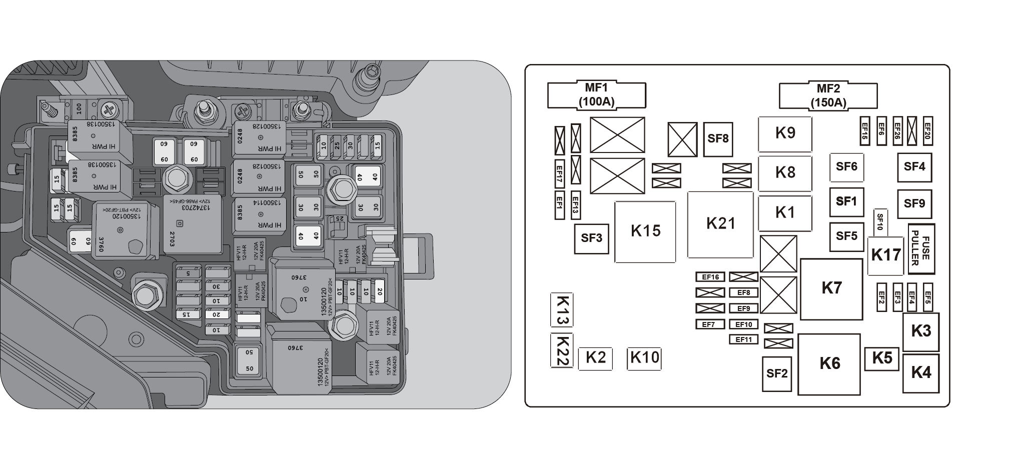
| “EF” Fuses | |||
|---|---|---|---|
| Fuse No. | Circuit | Fuse Rating | Color |
| EF1 | High Beam | 15A | Blue |
| EF2 | Low Beam LH | 10A | Red |
| EF3 | Low Beam RH | 10A | Red |
| EF4 | AC Clutch | 10A | Red |
| EF5 | Static Bending | 20A | Yellow |
| EF6 | Front Wiper | 25A | Brown |
| EF7 | Sensor | 15A | Blue |
| EF8 | Hose HTR | 30A | Green |
| EF9 | ECU | 10A | Red |
| EF10 | ECU | 20A | Yellow |
| EF11 | IGN 87 | 10A | Red |
| EF13 | Front Washer | 15A | Blue |
| EF15 | ABS/ESP3 | 10A | Red |
| EF16 | ECU/IGN | 5A | Brown |
| EF17 | Horn | 15A | Blue |
| EF20 | Front Fog Lamp | 15A | Blue |
| EF26 | ITM/Battery fuse | 30A | Green |
| “SF” Fuses | ||
|---|---|---|
| Circuit | Fuse Rating | |
| SF1 | Start/IGN SW2 | 30A |
| SF2 | Cooling Fan | 40A |
| SF3 | Glow Plug | 60A |
| SF4 | ABS /ESP 1 | 40A |
| SF5 | Cooling Fan 2 | 50A |
| SF6 | IP B+2 | 50A |
| SF8 | IP B+1 | 60A |
| SF9 | IGN SW 1 | 30A |
| SF10 | ABS /ESP 1 | 25A |
| Relays | ||
|---|---|---|
| Relay No | Circuit | Color |
| K1 | Start | Grey |
| K2 | DRL | |
| K3 | Low Beam | Black |
| K4 | Horn | Black |
| K5 | Static Bending | |
| K6 | Cooling Fan High | Grey |
| K7 | Cooling Fan Low | Grey |
| K8 | Front Wiper On | Black |
| K9 | Front Wiper Speed | Black |
| K10 | Horn | |
| K15 | Glow Plug | Grey |
| K17 | Spare 4 | Black |
| K18 | Spare 5 | Grey |
| K21 | Main | Grey |
| K22 | High Beam | |
2.5.2 Instrument Panel Fuse Box

Fully open the driver door and slide the driver seat backwards. The main central fuse box is located on the right side of the instrument panel. Price out the securing cover to access the fuse box.

| Fuses | |||
|---|---|---|---|
| Fuse No. | Circuit | Fuse Rating | Color |
| 1 | ECPS | 5A | Brown |
| 2 | ECU | 15A | Blue |
| 3 | Cluster/AWD | 5A | Brown |
| 4 | Audio ACC | 15A | Blue |
| 5 | Vanity lamp | 5A | Brown |
| 6 | MBFM Start | 5A | Brown |
| 7 | MBFM BATT3 | 20A | Yellow |
| 8 | MBFM FL -Window | 25A | Black |
| 9 | Mirror Folding | 10A | Red |
| 10 | Rear Wiper ACC | 10A | Red |
| 11 | Key In | 5A | Brown |
| 12 | Accessory | 5A | Brown |
| 13 | Front Blower | 30A | Green |
| 14 | Rear Blower | 20A | Yellow |
| 15 | Rear Defogger | 20A | Yellow |
| 16 | Power Socket Rear | 15A | Blue |
| 17 | Power Socket MID | 15A | Blue |
| 18 | Power Socket Front | 15A | Blue |
| 19 | Rear Wiper | 10A | Blue |
| 20 | Rear Washer | 10A | Blue |
| 21 | Rear Fog lamp | 5A | Brown |
| 22 | HVAC ACC | 10A | Red |
| 23 | ACC Blower | 5A | Brown |
| 24 | 5A | Brown | |
| 25 | Rain Light Sensor | 5A | Brown |
| 26 | Roof / Map Lamp | 5A | Brown |
| 27 | Memory-Cluster / HVAC | 15A | Blue |
| 28 | MBFM FR Window | 25A | Black |
| 29 | MBFM RR Window | 25A | Black |
| 30 | MBFM RL Window | 25A | Black |
| 31 | MBFM Battery 1 | 25A | Black |
| 32 | MBFM Battery 2 | 30A | Green |
| 33 | Audio / BATT | 15A | Blue |
| 34 | Airbag | 15A | Blue |
| 35 | Reverse lamp | 10A | Blue |
| 36 | Audio (Infotainment) / IGN | 15A | Blue |
| 37 | Spare | 5A | Brown |
| 38 | Spare | 10A | Red |
| 39 | Spare | 15A | Blue |
| 40 | Spare | 20A | Yellow |
| 41 | Spare | 25A | Black |
| 42 | Spare | 30A | Green |
| Relays | |||
|---|---|---|---|
| Relay No. | Circuit | Relay Rating | Color |
| 43 | Rear Defogger Relay | 40A | Black |
| 44 | Not used | ||
| 45 | Accessory Relay | 50A | Grey |
| 46 | Front Blower Relay | 40A | Black |
| 47 | Rear Blower Relay | 20A | Blue |
| 48 | Rear Fog Lamp | 20A | Blue |
| 49 | Not used | ||
| 50 | Mirror Unfold Relay | 20A | Grey |
| 51 | Rear Wiper Relay | 20A | Blue |
| 52 | Mirror Fold Relay | 20A | Grey |
| 53 | Rear Washer | 20A | Grey |
| 54 | Not used | ||
| 55 | Not used | ||
| 56 | Not used | ||
| 57 | Not used | ||
2.6 Flat Tyre
In case of a flat tyre during driving, reduce your speed gradually, keeping a straight line. Move cautiously off the road to a safe place well away from traffic. Park on a level spot with firm ground. Stop the engine and turn ON your hazard warning flashers.
Firmly apply the parking brake. Have everyone come out of the vehicle on the side away from traffic.
Never stop your vehicle in a traffic lane to change a tire. You could be hit by an oncoming vehicle. Keep driving until you reach a safe location.
Lifting a vehicle to change a tyre or perform maintenance is very dangerous if you do not have the requisite tools, safety equipment and training. The jack provided along with the vehicle is to be used only for changing a spare tire. It is never to be used to perform any other maintenance or repair on the vehicle.
Never place any part of your body under any portion of the vehicle when it is supported only by the jack. You could be crushed by the vehicle if it falls off a jack. Keep by-standers away from the vehicle.
Find level, solid ground that is clear of oncoming traffic. If you cannot find a safe place to stop, it is better to drive on a flat tyre and damage the rim than it is to risk being hit by oncoming traffic.
After changing a flat tire, never store the tyre or other equipment in the passenger compartment of the vehicle. This loose equipment could strike an occupant in the event of a sudden stop or collision. Store all of these items in the proper place.
2.6.1 Tool Kit
The tool kit is located behind the third row seats on the floor.
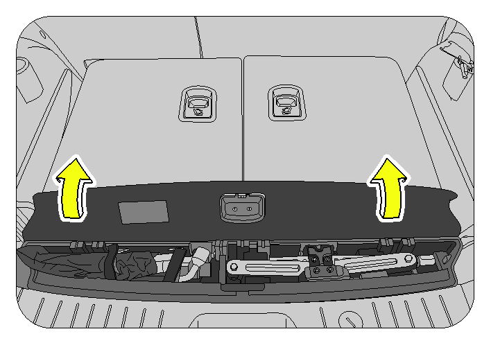
The tool kit consists of the following tools packed in a PVC tool bag;
- Assembly Screw Jack
- Jack Operating Lever
- Wheel Spanner
- Tow Bar
- DEO Spanner 10mm x 12mm
- Screw Driver
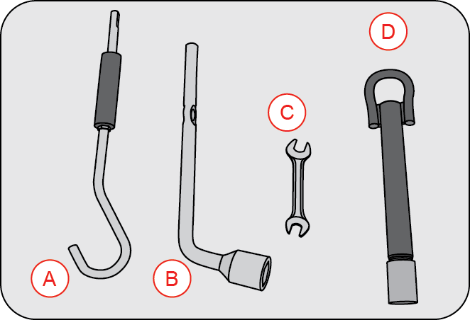
| A | Jack Operating Lever |
| B | Wheel Spanner |
| C | DEO Spanner 10mm x 12mm |
| D | Tow Bar |
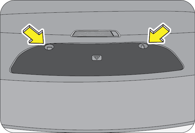
The warning triangle is located on the rear door trim below the camping lamp. Rotate the two securing knobs and lower the hinged cover. Un-strap the two holding belts and remove the warning triangle pouch.
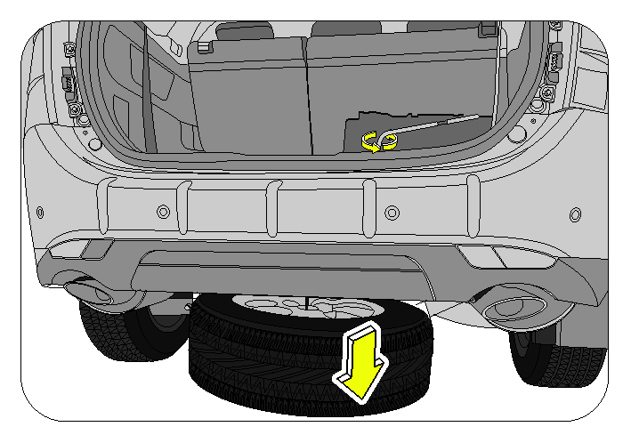
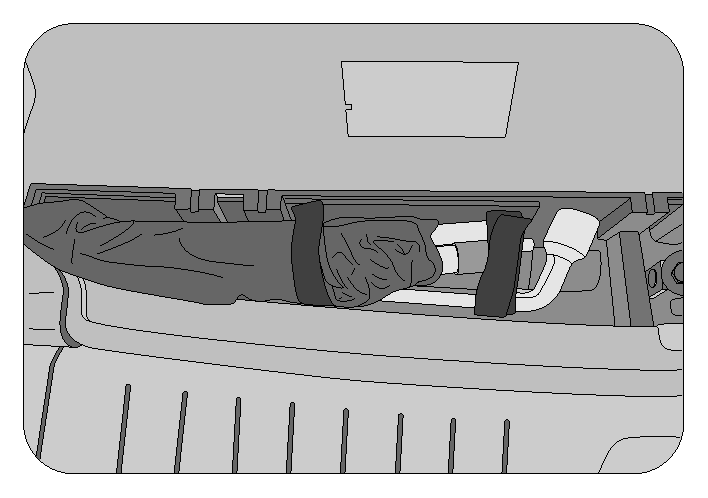
2.6.2 Spare Wheel Removal
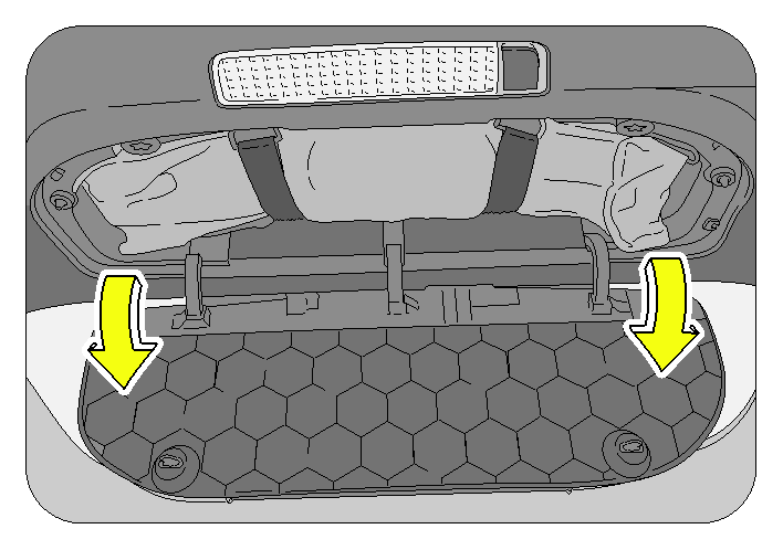
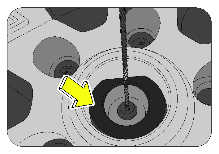
Spare wheel is located below the floor at the rear end of the vehicle. It is held in place by a securing nut underneath the rear luggage compartment floor carpet.
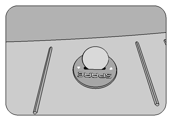
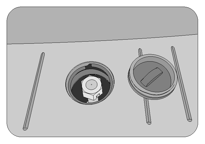
- Locate the plug covering the securing nut below the rear luggage compartment floor carpet. Remove the plug using a coin.
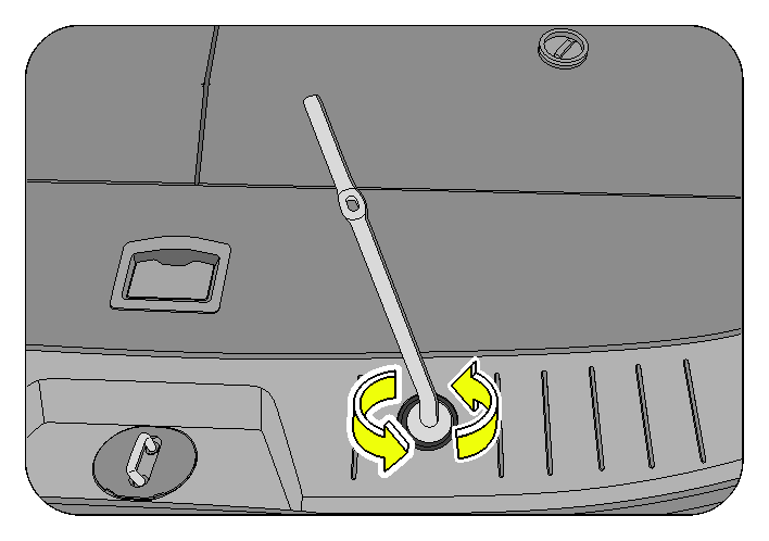
- Loosen the securing nut counter clockwise to winch down/lower the secured spare wheel to the ground.
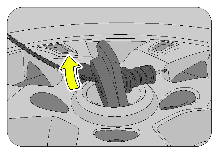
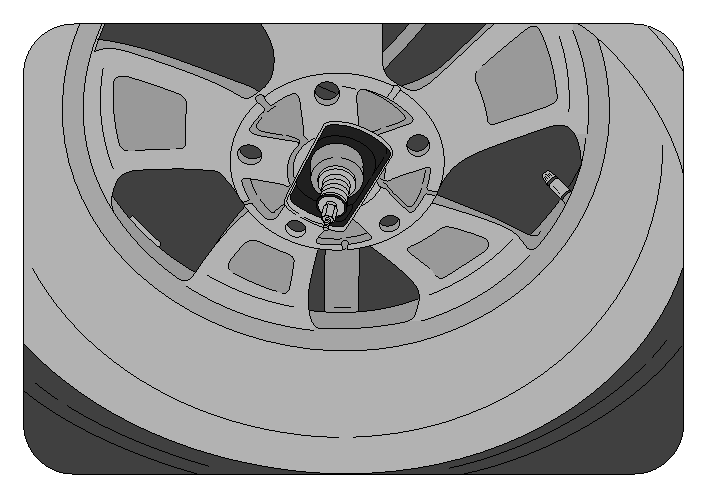
- Rotate the securing bracket counter clockwise and remove it out of the spare wheel hub Remove/pull away the spare wheel
To remove the wheel cover, wrap the tip of a screw driver with cloth, insert it near the lugs of the wheel cover and pry the cover away from the wheel.
Do not try to pry off the wheel cover by hand alone. Take due care in handling the wheel cover to avoid unexpected personal injury.
2.6.3 Wheel Nut Loosening
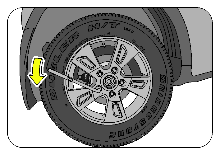
Always loosen the wheel nuts before raising the vehicle. Turn the wheel nuts counter clockwise to loosen. To get maximum leverage, fit the spanner to the nut so that the handle is on the right side. Grab the spanner near the end of the handle and push down on the handle. Be careful that the spanner does not slip off the nut. Do not remove the nuts, but loosen them by one or two turns.
Do not apply force with your legs (or stand) on the wheel spanner while tightening the wheel nuts.
| A | Flat Tyre | B | Chocks Blocks |
Block the wheel diagonally opposite the flat tyre to keep the vehicle from rolling when it is jacked up. When blocking the wheel, place a wheel block in front of one of the front wheels or behind one of the rear wheels
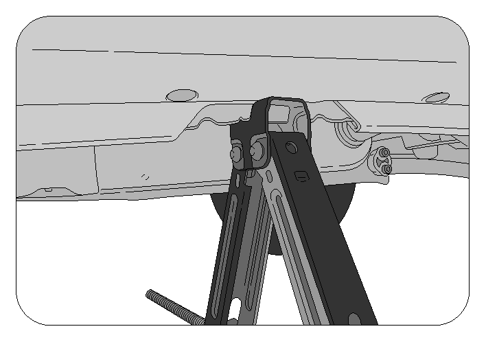
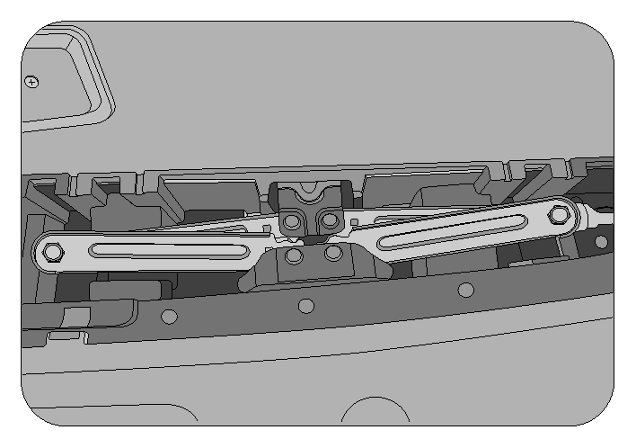
2.6.4 Jacking
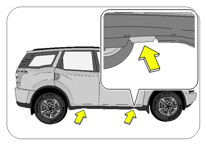
Locate the jack points in the front or rear as needed. They can be identified by a slot used to fit the jack precisely.
Position the jack at the correct jacking point. Make sure the jack is positioned on a level and solid place.
To raise the vehicle, insert the jack handle end with the jack operating lever, wheel spanner square slot into the jack operating lever and turn it clockwise with the handle. As the jack touches the vehicle and begins to lift, check that it is properly positioned.
Ensure no one is in the vehicle. Raise it high enough so that the spare tyre can be installed. Remember you will need more ground clearance when putting on the spare tyre than when removing the flat tire. 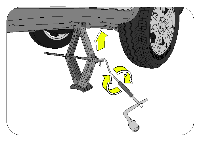
Make sure to set the jack properly in the jacking point. Raising the vehicle with jack improperly positioned will damage the underbody of vehicle or may allow the vehicle to fall off the jack and cause personal injury.
Never get under the vehicle when the vehicle is supported by the jack alone.
Remove the wheel nuts. Lift the flat tyre straight off and place it aside. Roll the spare wheel into position and align the holes in the wheel with the bolts. Lift up the wheel and get at least the top bolt started through its hole. Wiggle the wheel and press it back over the other bolts.
Before putting on the wheels, remove any corrosion on the mounting surfaces with a wire brush or such. Installation of wheels without good metal to metal contact at the mounting surface can cause wheel nuts to loosen and eventually cause a wheel to come off while driving.
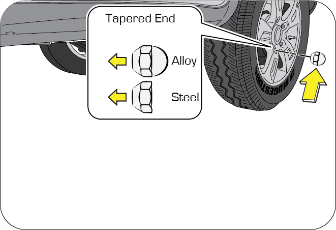
Reinstall the wheel nuts with the tapered end inward and tighten by hand. Press the wheel inward and tighten the wheel nuts further.
Never use oil or grease on the bolts or nuts. Doing so spanner slip, damage the bolts and also may cause personal injuries. Also, nuts may loosen and the wheels may fall off, which could cause a serious accident. If there is oil or grease on any bolt or nut, clean before installing wheel nuts.
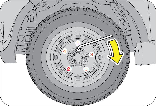
Lower the vehicle completely and tighten the wheel nuts using the wheel nut spanner. Turn the jack operating lever counter clockwise using the wheel nut spanner to lower the vehicle, making sure the handle remains firmly fitted onto the jack handle extension. Do not use other tools or any additional leverage other than your hands, such as a hammer, pipe or your foot. Make sure the spanner is securely engaged over the nut. Tighten each nut a little at a time in the diagonally opposite order. Repeat the process until all the nuts are tight.
Improperly or loosely tightened wheel nuts are dangerous. The wheel could wobble or come off. This could result in loss of vehicle control and cause a serious accident. Always make sure all the wheel nuts are properly/securely tightened to the specified torque.
When lowering the vehicle, make sure all portions of your body and all other persons are clear off the vehicle as it is lowered to the ground. Have the wheel nuts tightened with the torque spanner to 83 -104Nm, as soon as possible after changing wheels.
Put the wheel cover into position aligning the nozzle on the wheel to the nozzle clearance on the wheel cover. Tap it firmly on the sides with your hand to snap it into place.
2.6.5 Restore all the Tools, Jack and Flat Tyre Securely
Replace the tools (jack, wheel spanner, etc.,) in their storage locations.
Align the spare wheel bracket to the centre hub of the wheel. Winch up the flat tyre to the floor at the rear of the vehicle. Firmly tighten the securing nut and put the floor carpet back.
Double check to ensure the tyre is snug against the rear floor of the vehicle. The spare wheel bracket/cable may be damaged if the vehicle is driven with the spare wheel loosely mounted.
Drive slowly to the nearest service station and inflate to the correct pressure. Always reinstall the valve cap after checking or adjusting tyre pressure, dirt and moisture could get into the valve core and cause air leakage or valve damage.
2.7 Identifying Components in the Engine Compartment
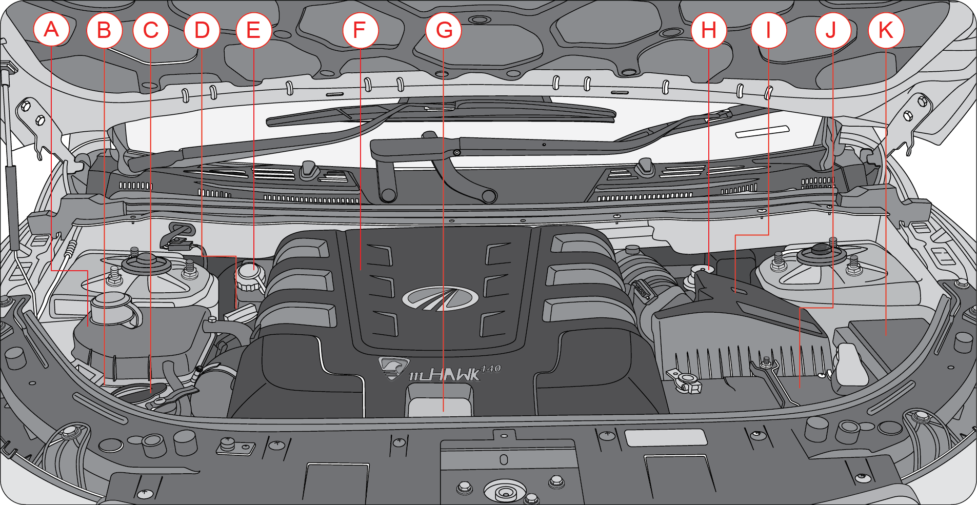
| A | Degassing Tank | G | Dipstick |
| B | Power Steering Fluid Reservoir | H | Fuel Priming Pump |
| C | Front Windshield Washer Fluid Reservoir | I | Air Filter Assembly |
| D | Engine Oil Cap | J | Battery |
| E | Brake/Clutch Fluid Reservoir | K | Engine Compartment Fuse Box |
| F | Engine Cover |
2.8 Technical Specifications
| Technical Specifications | |||
|---|---|---|---|
| ENGINE - mHawk | |||
| Displacement/Cubic Capacity | 2179 cc | ||
| Type | 4 Stroke, Turbocharged, DI engine | ||
| Compression Ratio | 16.5 : 1 | ||
| Max. Engine Output (kW @ rpm) | 103 kW @ 3750 rpm | ||
| Max. Torque (Nm @ rpm) | 330.0 Nm @ 1600 to 2800 rpm | ||
| TRANSMISSION | |||
| Type | 6 Speed Synchromesh | ||
| No. of Gears | 6 Forward, 1 Reverse | ||
| GEAR RATIOS | Transaxle Ratio | Final Drive Ratio | Overall Ratio |
| I | 4.15 | 4.05 | 16.823 |
| II | 2.14 | 4.05 | 8.679 |
| III | 1.24 | 4.05 | 5.035 |
| IV | 0.94 | 4.05 | 3.842 |
| V | 1.02 | 3.115 | 3.2 |
| VI | 0.87 | 3.115 | 2.716 |
| Reverse | 4.96 | 3.115 | 15.457 |
| STEERING | |||
| Type/Description | Hydraulic, Rack and Pinion, Power Assisted | ||
| Steering Wheel Diameter | 380 mm | ||
| BRAKES | |||
| Service Brake | Hydraulic, Vacuum Assisted, ABS | ||
| Front | Ventilated Disc | ||
| Rear | Disc | ||
| Parking Brake | Integral Park Brake acting on Rear Wheels | ||
| WHEELS & TIRES | |||
| Rim | 7J X 17 Regular (Alloy & Steel) | ||
| Tyres | P235/65 R17 | ||
| Type | Radial Tubeless | ||
| Laden Tyre Pressure (front & rear), (kg/cm 2) |
Front - 2.2 Kg/cm 2, Rear - 2.0 kg/cm 2 | ||
| FUEL | |||
| Fuel Capacity | 70 ± 2 liters | ||
| ELECTRICAL SYSTEM | |||
| System Voltage | 12V | ||
| Battery | 12V, 90 Ah | ||
| Remote Keyless Entry Battery | 3V, CR2032 | ||
| WEIGHTS | |||
| Kerb weight kg | 1785±15 for FWD and 1860±15 for AWD | ||
| Maximum GVW kg | 2450 | ||
3 VEHICLE OVERVIEW
3.1 Front Overview
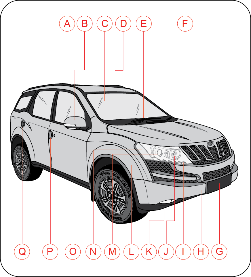
| A | Turn Signal on ORVM |
| B | Outside Rear View Mirror (ORVM) |
| C | Front Windshield |
| D | Ski Rail |
| E | Windshield Wiper |
| F | Hood |
| G | Front License Plate |
| H | Front Bumper |
| I | Parking Lamp |
| J | Head lamp High Beam |
| K | Fog Lamp |
| L | Static Bending Lamp |
| M | Head lamp Low Beam |
| N | Front Turn Signal Lamp |
| O | Puddle Lamp |
| P | Driver Door Handle |
| Q | Rear Door Handle |
3.2 Rear Overview
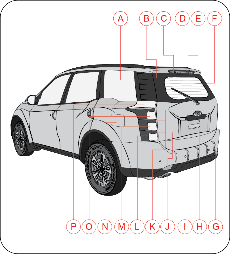
| A | Rear Quarter Window |
| B | Rear Windshield |
| C | High Mounted Stop Lamp |
| D | Rear Wiper |
| E | Rear Windshield Washer |
| F | Rear Windshield De-mister |
| G | Rear Bumper |
| H | Rear License Plate |
| I | Reverse Park Assist System (RPAS) Sensor |
| J | Rear Tail Gate |
| K | Rear Parking Lamps |
| L | Rear Fog Lamp |
| M | Reverse Lamp |
| N | Fuel Lid |
| O | Turn Lamp |
| P | Rear Stop Lamp |
3.3 Instrument Panel Overview
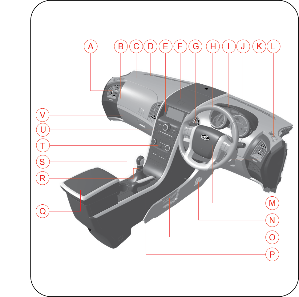
| A | Side Vents | L | Side Defrost Vents |
| B | Upper Glove Box | M | Horn Pad/Driver Airbag |
| C | Front Co-passenger Airbag | N | Foot Vents |
| D | Windshield Defrost Vents | O | Ticket Holder |
| E | Infotainment Screen | P | Parking Brake |
| F | Front Utility Box | Q | Armrest/Rear Bin Floor Console |
| G | Wiper Stalk | R | Transmission Gear Lever |
| H | Steering Wheel | S | Centre Bezel Switch Bank |
| I | Instrument Cluster | T | HVAC Controls |
| J | Light Combination Stalk | U | Infotainment Controls |
| K | Ignition Switch | V | Lower Glove Box |
4 INSTRUMENT CLUSTER OVERVIEW
4.1 Instrument Cluster
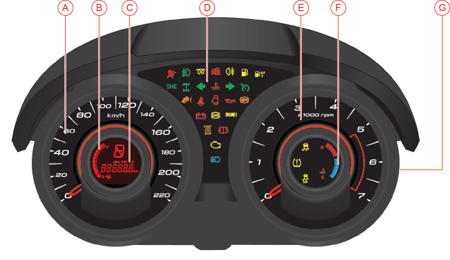
| A | Speedometer | E | Tachometer/RPM Gauge |
| B | Fuel Gauge | F | Temperature Gauge |
| C | Odometer/Trip meter/Gear Indicator | G | Reset Button |
| D | Warning/Telltale Lamps |
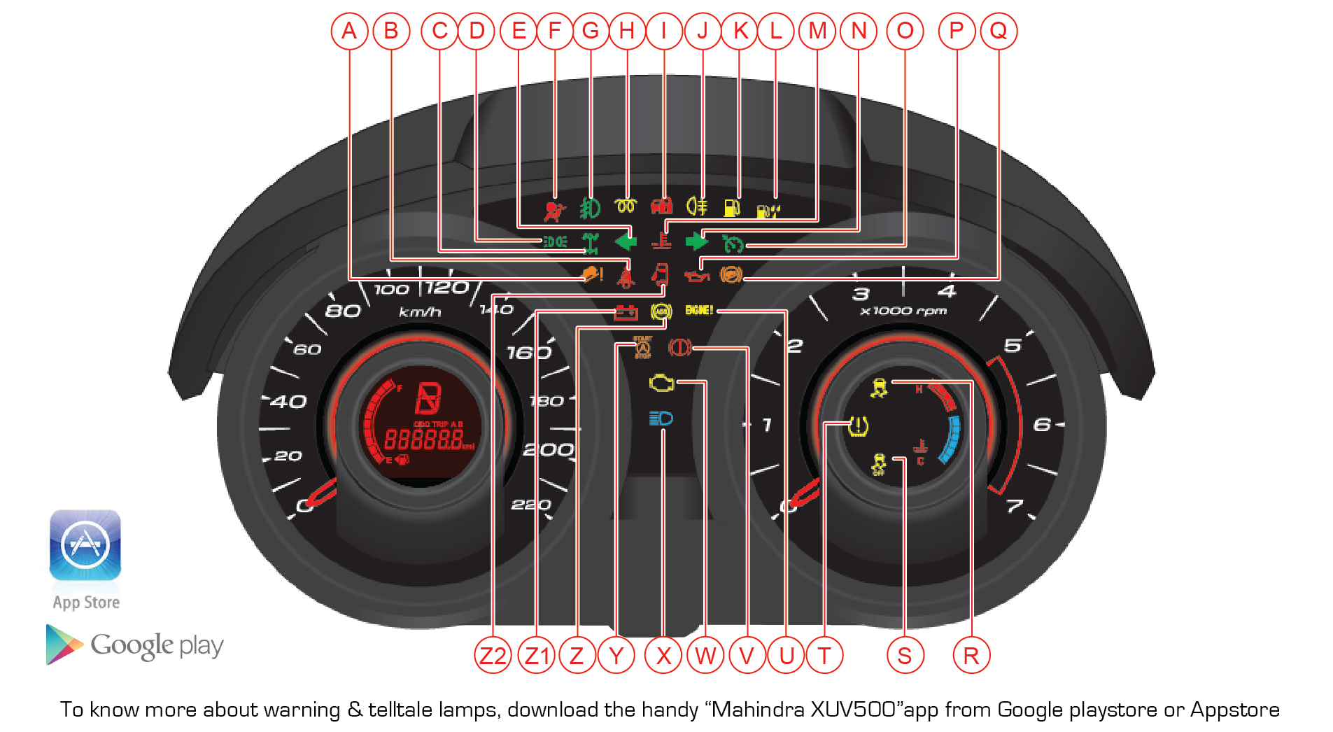
4.2 Warning Lamps Overview
| Sr. No. | Symbol | Warning Lamp/Tell Tale | Lamp Pre-check |
Lamp Status while Engine running | Action/Remarks |
|---|---|---|---|---|---|
| A | Hill Descent Control (HDC) | No | Continuously ON | Indicates a malfunction in Hill Descent Control System. Contact an Authorized Mahindra Dealer for assistance | |
| B | Seat Belt Warning Lamp | Yes | Continuously ON | If tell tale is not turning OFF even after fastening the seat belt, contact an Authorized Mahindra Dealer for assistance | |
| C | Interactive Torque Management (ITM) Warning Lamp | No | Continuously ON | Indicates a malfunction in the ITM system. Contact an Authorized Mahindra Dealer for assistance | |
| D |  |
Parking Lamp | No | Continuously ON | Indicates Parking Lamp is ON |
| E | Left Turn Indicator | No | Slow or Fast Blinking | Indicates left turn lamp is blinking Slow Blinking: Normal operation Fast Blinking: One /more left turn lamp bulb has fused. Have the bulb replaced |
|
| F | Airbag Warning Lamp * | For about 2 seconds | Continuously ON | Indicates malfunction of the airbag system. Contact an Authorized Mahindra Dealer immediately | |
| G | Front Fog Lamp Indicator * | No | Continuously Lamp ON | Indicates front fog lamp is ON. | |
| H | Glow Plug Indicator | For about 2 seconds | Continuously ON | Indicates a malfunction in the starting system. Contact an Authorized Mahindra Dealer immediately | |
| I | Vehicle Armed Status Lamp | No | Blinking | Slow Blinking: Vehicle is armed with the remote Fast Blinking/Continuously ON: Indicates a system malfunction. Contact an Authorized Mahindra Dealer immediately |
|
| J | Rear Fog Lamp Indicator * | No | Continuously ON | Indicates rear fog lamp is ON | |
| K |  |
Low Fuel Warning Lamp | No | Continuously ON | Indicates fuel level has reached the reserve level. Re-fuel immediately. |
| L | Water in Fuel Filter Warning | Yes | Continuously ON | Indicates water in fuel filter. Drain the water from filter or contact an Authorized Mahindra Dealer for assistance | |
| M | High Coolant Temperature Warning Lamp | Yes | Continuously ON | Engine temperature very high. Contact Authorized Mahindra Dealer immediately | |
| N | Right Turn Indicator | No | Slow or Fast Blinking | Indicates right turn lamp is blinking Slow Blinking: Normal operation Fast Blinking: One /more right turn lamp bulb has fused. Have the bulb replaced |
|
| O | Cruise Control Indicator * | Yes | Continuously ON | Indicates vehicle is in Cruise mode | |
| P | Low Engine Oil Pressure Warning Lamp | Continuously ON till Engine Starts | Continuously ON | Indicates engine oil pressure is low. Check oil level and top-up or contact an Authorized Mahindra Dealer for assistance | |
| Q | Hill Hold Control (HHC) | No | Continuously ON | Indicates a malfunction in Hill Hold Control System. Contact an Authorized Mahindra Dealer for assistance | |
| R | ESP System Warning Lamp | For About 2 Seconds | Continuously ON or Blinking | Blinking: Indicates ESC has taken control of the vehicle stability Continuously ON: Indicates a malfunction in the ESC system. Contact an Authorized Mahindra Dealer immediately |
|
| S | ESP OFF Lamp | No | Continuously ON | Indicates ESC OFF | |
| T | Tyre Pressure Monitoring System Lamp (TPMS) | For About 2 Seconds | Continuously ON or Blinking | Indicates low tyre pressure or possible malfunction in TPMS. Refer to TPMS section in FEATURES AND CONTROL/WHEELS AND TIRES chapter for further details | |
| U | Check Engine Lamp | For About 2 Seconds | Continuously ON or Blinking | Indicates a potential malfunction in the EMS, contact an Authorized Mahindra Dealer immediately | |
| V | Parking Brake ON/Brake Fluid Low Warning Lamp | Yes | Continuously ON | Either one of below conditions- 1. Park Brake might be engaged 2. Brake fluid level might be low 3. Front Brake Pads are worn Contact Authorized Mahindra Dealer immediately for assistance |
|
| W | OBD Check Lamp | Continuously ON till Engine Starts | Continuously ON | There is a potential malfunction related to emission system, contact an Authorized Mahindra Dealer immediately | |
| X | Headlamp High Beam Indicator | No | Continuously ON | Indicates Head lamp high beam is ON | |
| Y | Stop/Start Lamp | No | Continuously ON or Blinking | Continuously ON: Engine is in auto stop mode Blinking: Stop/Start is about to stop the engine |
|
| Z | ABS Warning Lamp * | For About 2 Seconds | Continuously ON | Indicates malfunction of the ABS system. Contact an Authorized Mahindra Dealer immediately | |
| Z1 | Charging System Warning Lamp | Continuously ON till Engine | Continuously ON | Indicates malfunction in charging system. Contact Authorized Mahindra Dealer for assistance | |
| Z2 | Door Ajar Warning Lamp | No | Continuously ON | Indicates one or more doors and/or boot/hood are open | |
| * if equipped / select models or variants only | |||||
4.3 Infotainment Overview
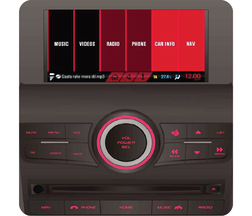
| KEY NAME | FUNCTION / DESCRIPTION |
|---|---|
| POWER / SELECT | Power ON / OFF, Select |
| VOLUME KNOB | Volume Up / Down |
| 1 | Programmed Memory 1 |
| 2 | Programmed Memory 2 |
| 3 / FLR- | Programmed Memory 3 / Folder Down |
| 4 / FLR+ | Programmed Memory 4 / Folder Up |
| 5 | Programmed Memory 5 |
| 6 | Programmed Memory 6 |
| CLK | Clock Settings and Toggling between 12 And 24 Hrs |
| BAND | Band Selection |
| SEEK DOWN | Previous Track / Fast Rewind |
| SEEK UP | Next Track / Fast Forward |
| EQ | Equalizer Settings |
| FAV | Favorite Tuner Memory Selection |
| RPT | Repeat |
| RDM | Random |
| SOURCE | Source Selection |
| INFO | Track Information |
| MUTE | Audio Mute |
| EJECT | CD Eject |
5 SEATS AND SEAT BELTS
5.1 Front Seats
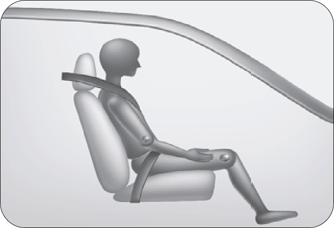
5.1.1 Sitting in Correct Position
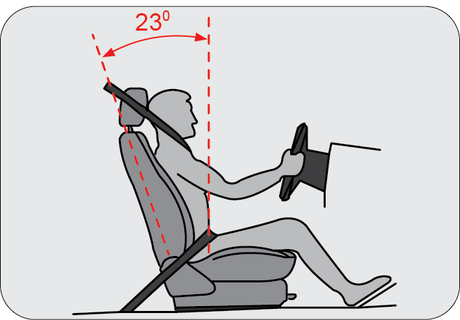
Follow the tips below for a comfortable and safe journey;
- Sit in an upright position with the base of your spine pressed against the seat back
- The driver and front passenger seat head restraint has 5 positions. Adjust it as close as possible to the above specified position, with the top of the head restraint even with the top of your head
- Maintain sufficient distance between yourself and the steering wheel. Maintain at least a ten inch (10") distance from the centre of the steering wheel to your chest
- The top curve of the steering wheel should align with your chin for ideal road visibility
- Adjust your seat and seat back angle such that your wrists rest on the steering wheel
- Ensure your legs are in bent position while fully depressing the clutch pedal.
The seat should be adjusted while still maintaining control of the foot pedals (able to fully depress the clutch pedal), steering wheel (rest the wrists on the steering wheel) and your view of the instrument panel controls.
Never adjust the driver's seat while the vehicle is in motion. The seat may unexpectedly move and cause the driver to unintentionally operate the accelerator or brake, or turn the steering wheel, causing loss of control of the vehicle, an accident or serious personal injury. Adjust the driver's seat only when the vehicle is not in motion.
Never put objects under the seats. They may interfere with the seat-lock mechanism or unexpectedly activate the seat position adjusting lever, causing the seat to suddenly move, resulting in loss of control of the vehicle, an accident or serious personal injury.
While adjusting the seat, do not put your hands under the seat or near the moving parts. This may lead to injuries.
5.1.2 Front Seat Slide
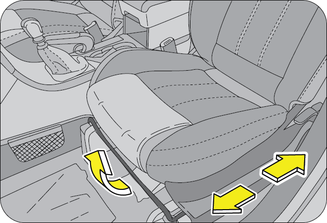
Move the seat forward or backward by lifting the adjustment lever located under the seat front and release once the desired position is reached.
While adjusting the seat, make sure the latch engages fully and the seat is locked firmly in the desired position. An unlocked seat may move in a sudden stop or collision, causing injury to the person in that seat. Push and pull on the seat to be sure it is locked.
5.1.3 Front Seat Recline
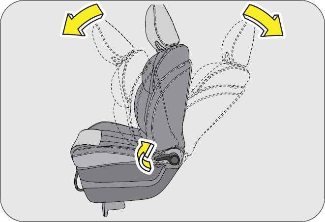
To adjust the seat back, lift the lever located on the outboard side of the seat, lean back, and release the lever at the desired position. To return the seat back, lift the lever, lean forward, and release the lever.
The seat belts provide maximum protection in a frontal or rear collision when the occupants are sitting up straight and well back in the seats. If you are reclined, the lap belt may slide past your hips and apply restraint forces directly to the abdomen, or the shoulder strap may contact your neck. The more the seat is reclined, the greater the risk of serious injury.
When returning the rear-reclined seat back to its upright position, make sure you support the seat back while operating the lever.
5.1.4 Front Seat Lumbar Adjustment (if equipped)
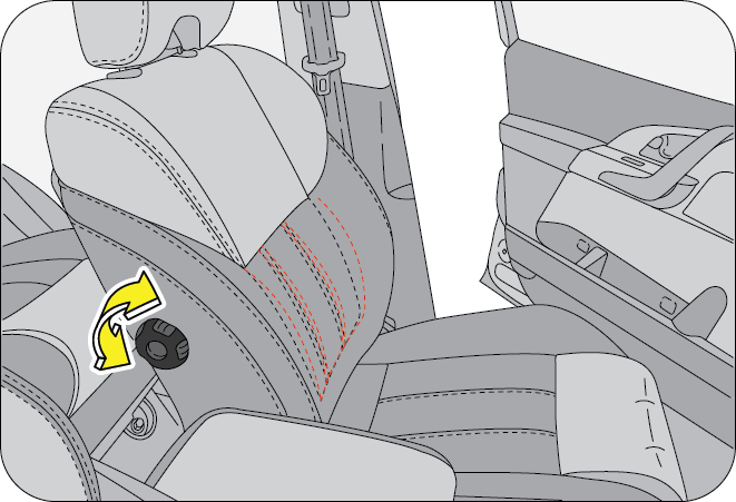
Both the front seat backs feature lumbar adjustment. The lumbar contour of the lumbar support can be adjusted by means of the adjusting wheel on the inner side of the seat back.
Properly adjusted lumbar support provides adequate back support essential during long journeys.
Do not use force rotate the lumbar adjustment lever beyond the extreme stop positions in either direction.
5.1.5 Front Seat Height Adjustment
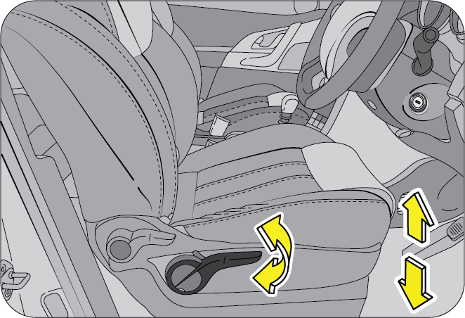
The driver seat height can be raised or lowered to three positions.
To RAISE the seat height, lift the seat height adjust handle while there is no load or prior to occupying the seat. Release the lever once desired seat height is reached.
To LOWER the seat height, lift the seat height adjust handle while seated in the driver seat. Release the lever once desired seat height is reached.
5.2 Head Restraint
The head restraint comprises of the padded portion which contacts your head and is inserted/locked in receptacles on the top of the seat back.
5.2.1 Adjustable Head Restraint
Your vehicle seats are equipped with head restraints which are vertically adjustable. The purpose of these head restraints is to help limit head motion in the event of rear collision.
Always align top of the head restraint with the top of your head or as close to it as possible. To raise the head restraint, press the lock knob and pull the restraint up. To lower the head restraint, press the lock knob and push the head restraint down.
5.2.2 Removing Seat Head Restraint
The head restraint can be pulled out completely by depressing the locking button while pulling the restraint out.
5.2.3 Installing Seat Head Restraint
Align the head restraint shafts over the holes on the seat top and push the restraint straight down till you hear the lock click.
Keep the seat back as upright as possible so the headrest is behind, not beneath, and almost touching your head.
Never drive with the head restraints not properly adjusted, head restraints removed or inserted in a flipped condition. With no support behind your head, your neck could be seriously injured in a collision.
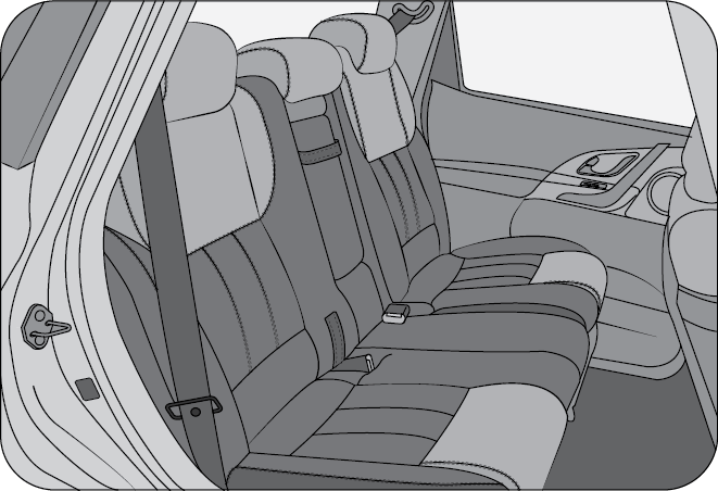
5.3 Second Row Seats
Loading luggage on the seats is dangerous. The luggage can become a projectile that could hit and injure passengers in a sudden stop or collision. Luggage should always be kept on the floor.
To avoid serious injury, do not sit on or place objects on a folded seat back while the vehicle is moving.
5.3.1 Second Row Seat Recline
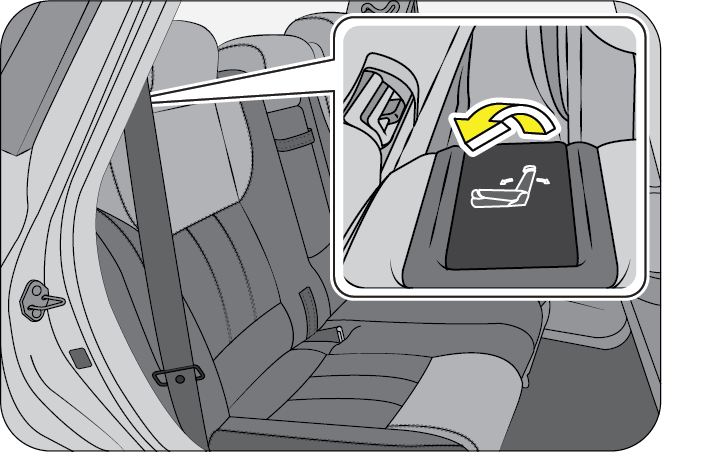
To change the second row seat back angle, lean forward slightly while raising the recline lever on the top corner of the seat back, lean back to the desired position and release the recline lever. Make sure the recline lever returns to its original position and the seat back is locked in place by rocking the seat back forward/backward.
When returning the rear-reclined seat back to its upright position, make sure you support seat back while operating the lever.
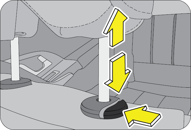
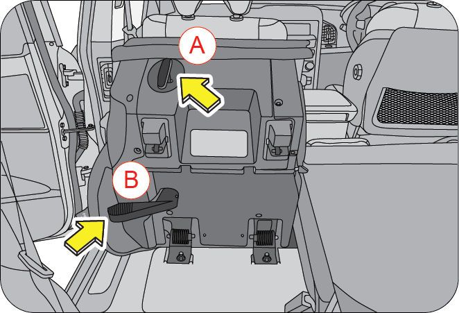
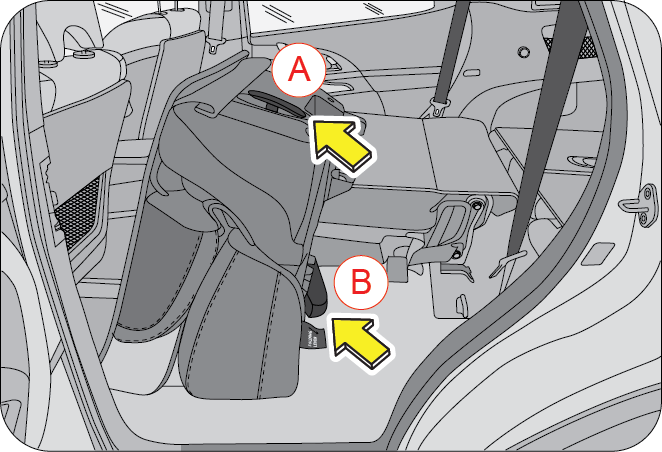
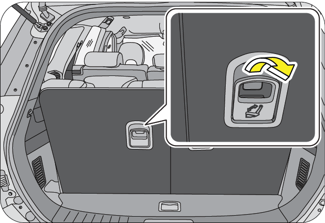
5.3.2 Second Row Seat Folding (Third Row Seat Access)
The second-row seat can be flipped forward to provide more cargo space.
- Lower the second-row seat head restraint to the lowest position (else it will obstruct and hit the floor)
- Insert the lap belt into the pocket of the seat bottom
- Recline the seat back to full forward direction
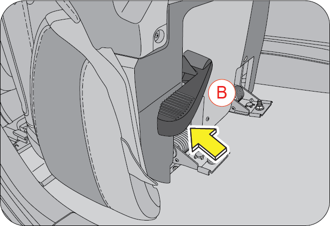
- Push side actuation lever (B) in forward direction for Ingress, OR
- Pull rear actuation lever (A) for Egress
- Push seat back to rear side of vehicle for locking
- Pull seat back for upright position till it locks in design position
- Push seat cushion downward by sitting on it (>45 kg) for locking seat cushion
Return the seat back to its upright position in one continuous motion to securely lock the seat and in turn avoiding seat flipping forward suddenly leading to injuries. If this happens, release the seat lock by pulling the lever and repeat the procedure.
Be cautious when placing your hands around the seat anchors. You could pinch your hands or fingers between the seat anchor and the seat. Hold the edge of the seat when lowering it into place. Never place your hands between the seat anchor and the seat.
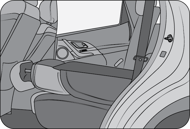
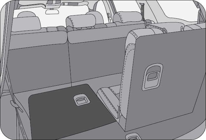
5.4 Third Row Seats
Access to or exit from third row seat and luggage area is possible by completely folding the second row seat. Second row seat features 60:40 split configuration. Instead of folding the complete seat back and seat cushion, the required seat alone can be folded to gain access to third row seat.
Refer to the previous sections for details regarding folding of second row seats.
5.4.1 Third Row Seat Folding
To fold the third row seat, unlock the seat back by pulling the lever on the rear of the seat back outwards.
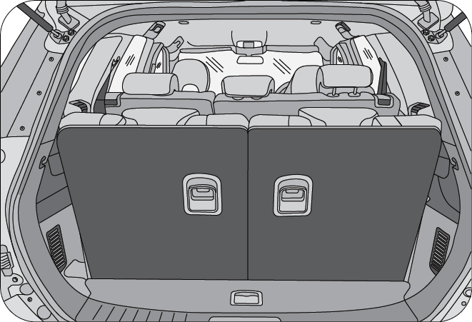
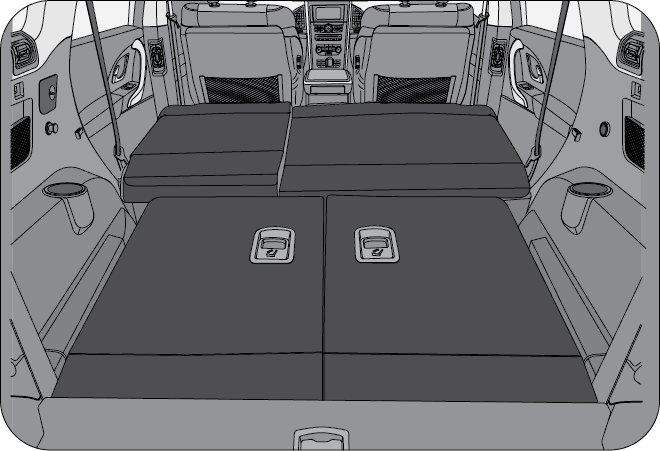
Similarly lower the other half of third row seat to get a completely flat surface.
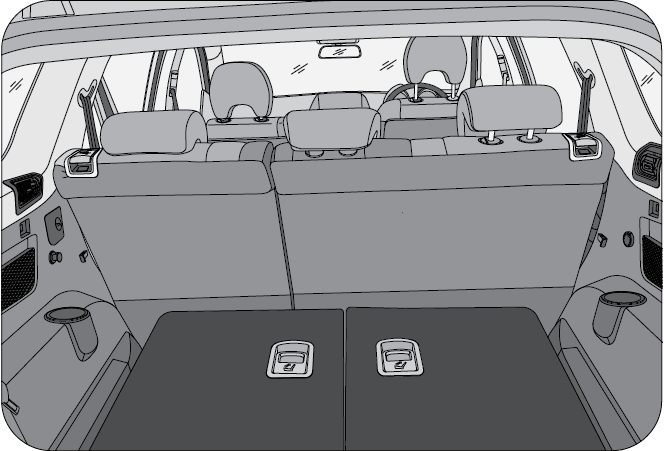
Both the second row and third row seats can be folded flat to maximise the luggage space.
5.5 Seat Belts
At least once each month, inspect the seat belt webbing for any cuts, tears, or other signs of wear (such as fraying along the edges). Also inspect the anchors, retractors, and buckles to be sure they are tight and operational.
5.5.1 General Warnings and Instructions
- All occupants, including the driver, should always wear their seat belt no matter how short the trip in order to minimize the risk of severe injury in the event of a crash. In an accident, an unbelted passenger becomes a projectile, and can cause serious injury to himself or another passenger.
- In a rollover crash, an unbelted person is significantly more likely to die than a person wearing a seat belt
- Some people believe that wearing a seat belt will lead to entrapment in the vehicle after an accident. However, your chances of surviving the initial impact, being able to unbuckle yourself and escaping from the vehicle is much greater if you are belted.
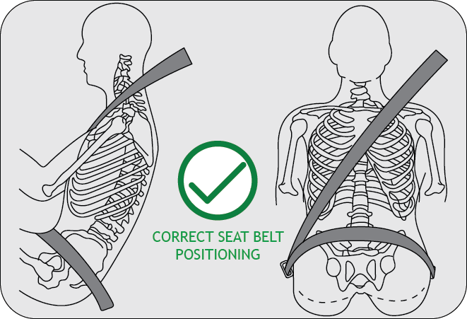
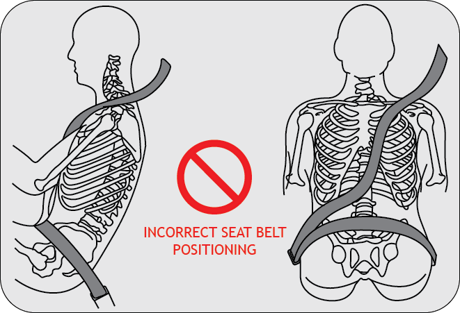
- In order to be properly buckled, you must always sit up straight and keep your feet on the floor in front of you. The lap part must be worn low and tight across your hips, just touching the top of your thighs. While fastening the seat belt, the shoulder strap of the seat belt must pass over your chest and top of your shoulder. It must never touch your neck, face, the side of your shoulder, arm, or pass under your arm. The belt must always be flat against your body and not twisted in any way. Nothing, such as an arm rest, a pocketbook, or any external objects should be between you and the seat belt. Improper wearing of a seat belt will reduce the protection in an accident.
- Seat belts should be adjusted as tightly as possible, consistent with comfort to properly secure the wearer in the seat. A slack belt will greatly reduce protection to the user, and could cause additional injuries.
- The seat belts provided for your vehicle are designed for people of adult size, must be properly used and maintained.
- Passengers should not move out of or change seats while the vehicle is moving. A passenger who is not wearing a seat belt can be thrown against the inside of the vehicle, against other occupants, or out of the vehicle during a crash or emergency stop
- Do not use any accessories on seat belts or modify in any way the seat belt system. Devices claiming to improve occupant comfort or reposition the seat belt can reduce the protection provided by the seat belt and increase the chance of serious injury in a crash
- An accident or emergency stop, can damage your seat belt system, even if the accident is “minor”. Please have your Authorized Mahindra Dealer inspect the seat belt system after an accident
- Please be aware that any unsecured item in your vehicle, such as your pet, unsecured child restraint system, or a laptop, can become a projectile in the event of an accident or sudden stop, causing injuries to occupants in the vehicle
Never use a damaged seat belt system. A damaged seat belt will not provide protection in an accident, resulting in serious injury.
- Seat belt systems can be prone to abuse. They are not indestructible. They must be handled with care to avoid damage
- Keep the belts clean and dry. Belt retraction may become difficult if the belts and webbing are soiled. If they need cleaning, use a mild soap solution or lukewarm water. Never use bleach, dye, or abrasive cleaners. These chemicals will severely weaken the belts
- Retractors in 3-point type seat belts retract the seat belts when not in use. The inertia lock and coil spring allow the belts to remain comfortable on users during normal driving. During accidents or abrupt stops, inertia locks restrict the sudden forward movement of the wearer
- At least once each month, inspect the seat belt webbing for any cuts, tears, or other signs of wear (such as fraying along the edges). Also inspect the anchors, retractors and buckles to be sure they are tight and operating as intended to. In case of the slightest doubt, please have your Authorized Mahindra Dealer conduct a thorough inspection
5.5.2 Injured Person
Injured persons must also wear a seat belt while traveling. Consult your doctor for specific recommendations before travel.
5.5.3 Patients
Persons with serious medical conditions should also wear a seat belts. Consult your doctor for specific recommendations before travel.
5.5.4 Pregnant Women
Pregnant women must also wear seat belts. Consult your doctor for specific recommendations.
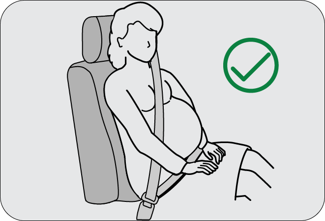
The lap belt should be worn snugly and as low as possible over the hips. The shoulder belt should be worn across your shoulder, but never across the stomach area. When worn properly, the seat belt will protect both the mother and the fetus in an accident or emergency stop.
A pregnant woman should never wear the seat belt across the stomach area. This could lead to serious injuries to the fetus and/or the pregnant mother.
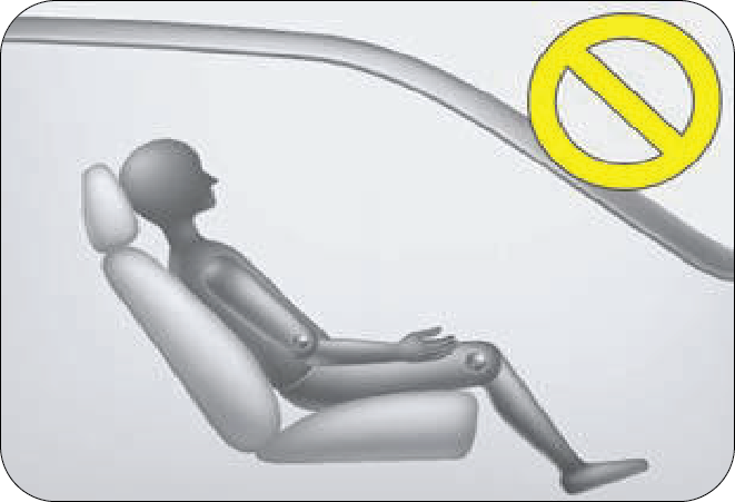
Never ride with the seat back reclined so that the seat belt is no longer resting against your chest. The seat belt provides maximum protection in a frontal or rear collision when the occupants are sitting up straight and well back in the seats. If you are reclined excessively, the lap portion of the belt may slide past hips and apply restraining forces directly to the abdomen, or the shoulder portion of the belt may contact the neck. The more the seat is reclined, the greater the risk of serious injury.
Never wear twisted seat belts. Excessive forces will be transferred from the belt to the wearer, in a collision, resulting in serious personal injury. Each seat belt is meant for use by one person only.
Using one seat belt for more than one person at a time is dangerous. The seat belt will not be able to spread the impact forces properly leading to serious injuries.
Never put a belt around a child being carried on the occupant's lap. This could lead to serious injuries. The child may be crushed in an accident or emergency stop.
5.5.5 Seat belt usage is necessary to:
- Reduce the possibility of being thrown from your
- Reduce the possibility of injuries to lower body and legs during an accident
- Hold the driver in a position which allows better control of the vehicle
Seat belts must also be worn by persons with injuries or patients with serious medical conditions. Consult your doctor for specific recommendations before travel.
Children who are too large for child restraint systems should always occupy the rear seat and use the vehicle seat belts. The lap portion of the seat belt should be fastened snugly on the hips as low as possible and the shoulder strap should be across the child's shoulder, not the neck or face. Use the seat belt height adjuster as necessary. If you are unable to position the strap across the child's shoulder, the child should remain in a booster seat. Frequently check the seat belt to be sure it remains snug and in position. A squirming child could cause the seat belt to come out of position.
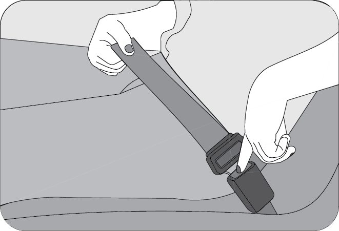
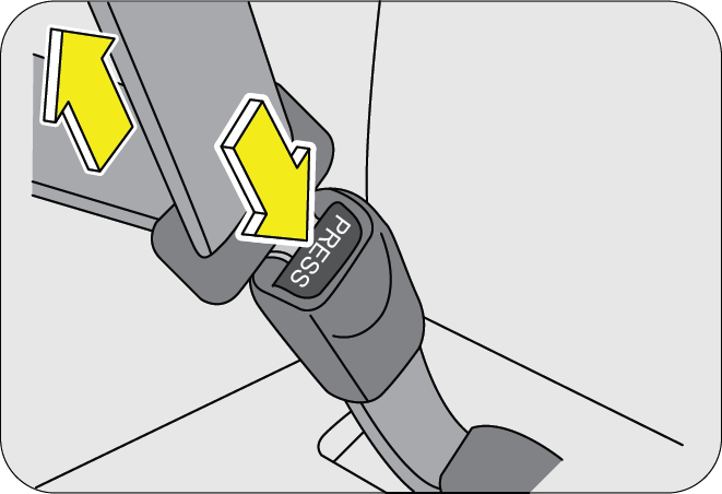
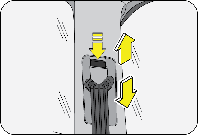
5.5.6 Fastening the Seat Belt (3-Point type)
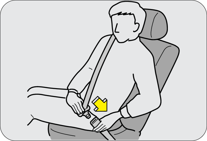
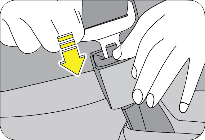
Adjust the seat as needed, sit up straight and well back in the seat. To fasten your seat belt, pull the webbing out of the retractor and insert the metal tab into the buckle. An audible “click” would be heard when the tab locks into the buckle. Pull up on the shoulder strap to tighten the lap belt across your hips. The seat belt retractor will pull in any slack in the shoulder strap. A slow and easy motion will allow the belt to extend and let you move your body around freely.
Periodically check the seat belt as you ride to be sure it remains snug and in position. If there is a sudden stop or impact, the belt will lock into position. It will also lock (restrict) if you try to lean forward too quickly.
If the driver or co-driver seat belt is not fastened when the ignition is switched ON, the seat belt warning lamp illuminates. Refer “Warning Lamps” in the “Features and Control” chapter for further details.
5.5.7 Fastening the Seat Belt (2-Point Lap type)
This seat belt is applicable to the second row middle passenger seat. Insert the tongue into the buckle until it snaps. Position the lap belt on the hips as low as possible.
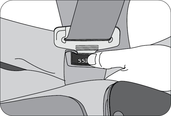
5.5.8 Unfastening the Seat Belt (both 3-Point & 2-Point)
To release the belt, press the buckle release button and allow the belt to retract. If the belt does not retract smoothly, pull it out and check for kinks or twists. Then make sure it remains untwisted as it retracts.
Never insert coins, clips, etc. in the buckle as this may prevent you from properly latching the tab and may cause damage to the buckle mechanism, thereby making the seat belt ineffective in an accident, resulting in serious personal injury.
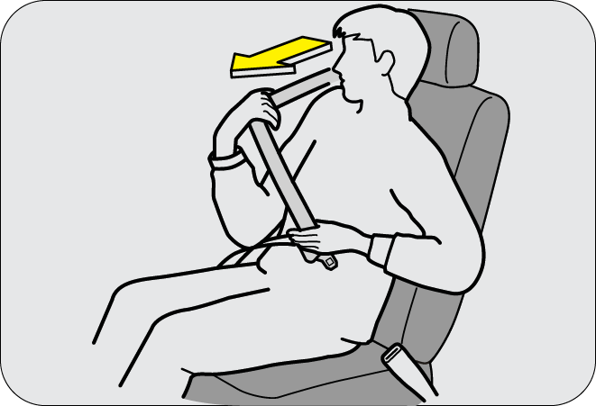
5.6 Seat Belt Height Adjuster
You can adjust the height of the shoulder belt anchor for maximum comfort and safety in both front seats. If the height of the seat belt is too near your neck, you will not be getting the most effective protection. The shoulder portion of the belt should be adjusted so that it lies across your chest and midway over your shoulder nearest to the door and not your neck.
To adjust the height of the seat belt anchor, lower or raise the height adjuster to an appropriate position while pressing the height adjuster button. Release the button to lock the anchor into position. Try sliding the height adjuster to make sure that it has locked into the position.
Adjust the shoulder belt height sitting well back in the seat. Do not adjust the seat belt height while vehicle is in motion.
5.7 Child Restraints
Use a child restraint system only if the child is not big enough to properly wear the seat belts. Else, use the regular seat belt instead of the child restraint system. Seat the child in the rear seat and use the seat belt. According to accident statistics, children are safer when properly restrained in the rear seat than in the front seat. Always secure a child in a proper child restraint system in accordance with age and size of the child as recommended by the child restraint system manufacturer.
Do not allow children to stand up or kneel on either the rear or the front seats. An unrestrained child could suffer serious injuries during emergency braking or collision.
It is also not recommended that children travel sitting on your lap as it does not provide sufficient restraint.
6 SUPPLEMENTARY RESTRAINT SYSTEM
The Supplementary Restraint System (SRS) includes airbag’s and ECU. The air bags are designed to provide further protection to the vehicle occupants in addition to the primary protection provided by the seat belts and seat belt pre-tensioners.
The primary components of the system are the sensors which measure when the air bags should deploy, and the air bag module housing the air bag inflation device along with the air bag. In the event of a significant frontal impact, the SRS airbag’s inflate to work in conjunction with the seat belts and help reduce injuries mainly to the driver's or front passenger's head/chest which could otherwise be injured.
All occupants, including the driver, should always wear their seat belts irrespective of presence of airbag to minimize the risk of severe injury in the event of a crash.
Seat belts are the primary restraint system in the vehicle. Air bag provides supplementary protection in addition to the seat belts. Air bags are more effective in reducing injuries when the seat belts are worn.
6.1 Airbag
- One frontal airbag for the driver (A)
- One frontal airbag for the front passenger (B)
- Two side (seat) impact airbag’s (C)
- Two curtain airbag’s (D)
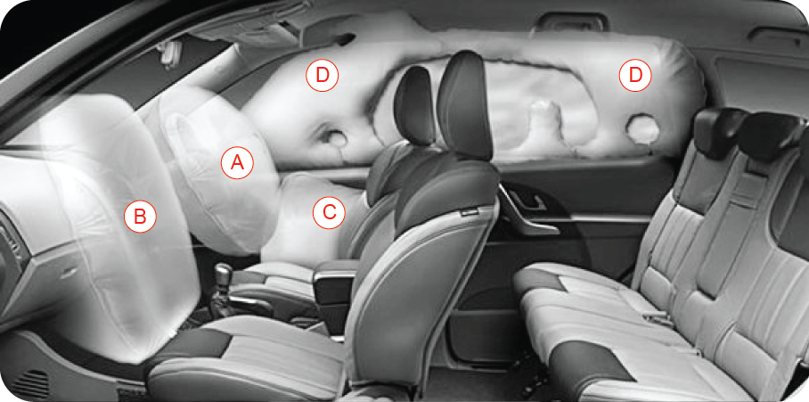
6.1.1 Airbag Location
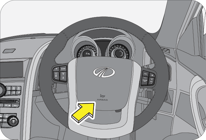
- In the steering wheel hub - Driver Airbag
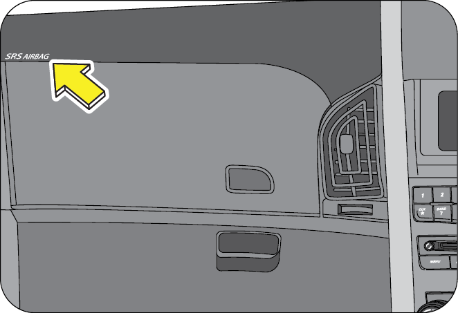
- Above the upper glove box - Passenger Airbag
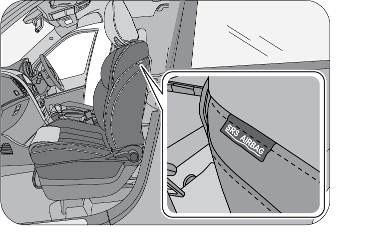
- Outboard side of driver and front passenger seats - Side Impact Airbag’s
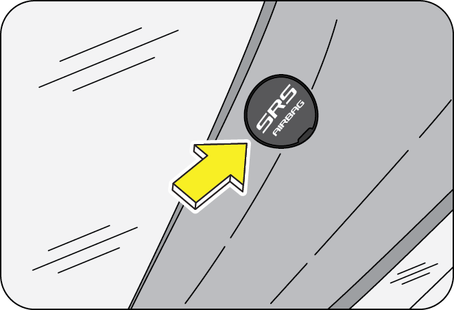
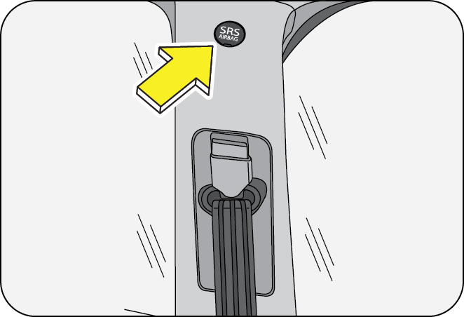
- In the inner roof rail (LH & RH) - Curtain Airbag’s
An airbag is not designed to deploy in every type of crash. Depending on the type of accident or impact, the front airbag’s, side airbag’s and curtain airbag’s independently deploy thereby protecting the occupants. It is not necessary that ALL the airbag’s deploy during an accident.
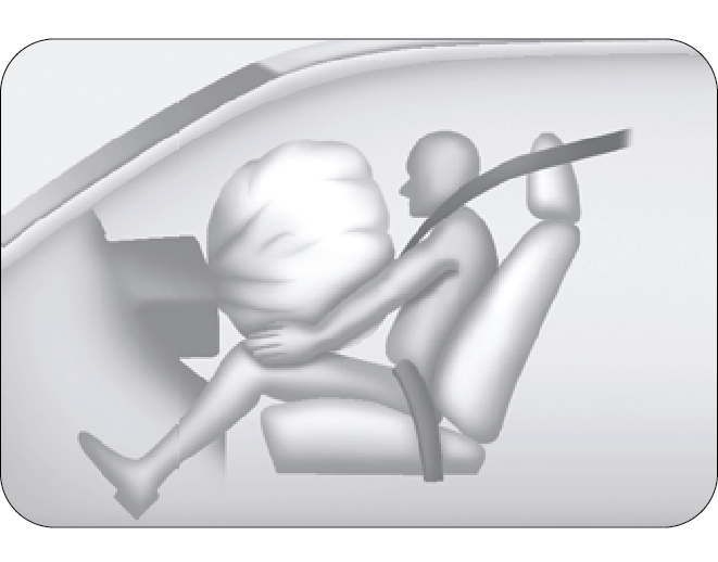
To minimize the risk of severe injury in the event of a crash, every passenger must always wear their seat belt (see the chapter on Seat Belts in this manual). The airbag’s inflate very quickly with great force. Do not position any part of your body too close to a airbag, you or especially children could be seriously injured by a deploying airbag.
6.2 Driver and Front Passenger Air Bag
Your vehicle is equipped with a Supplementary Restraint (Air Bag) System and lap/shoulder belts at both the driver and front passenger seating positions. The indications of the system's presence are the letters “SRS AIR BAG” embossed on the horn pad in the steering wheel and on the passenger side IP pad above the glove box.
The SRS consists of air bags installed under the pad covers in the centre of the steering wheel and the passenger's side front panel above the glove box.
The purpose of the SRS is to provide the vehicle's driver and/ or the front passenger with additional protection than that offered by the seat belt system alone in case of a frontal impact of sufficient severity.
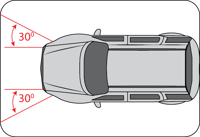
The SRS is designed to deploy the front air bags only when an impact is sufficiently severe and when the impact angle is less than 30° from the forward longitudinal axis of the vehicle.
Front air bags are not intended to deploy in side-impact, rear impact or rollover crashes. In addition, front air bags will not deploy in frontal crashes below the deployment threshold.
6.3 Side Impact Airbag
Your vehicle is equipped with side impact airbag’s in both the front seats. The purpose of the air bag is to provide the vehicle's driver and/or the front passenger with additional protection during side impacts or collisions.
The side impact air bags are designed to deploy only during certain side-impact collisions, depending on the crash severity, angle, speed and point of impact.
- The side impact air bag is supplementary to the seat belt systems and is not a substitute for them. Therefore your seat belts must be worn at all times while the vehicle is in motion. The air bags deploy only in certain side impact conditions severe enough to cause significant injury to the vehicle occupants.
- For best protection from the side impact air bag system and to avoid being injured by the deploying side impact air bag, all seat occupants should sit in an upright position with the seat belt properly fastened. The driver's hands should be placed on the steering wheel at the 9:00 and 3:00 positions. The passenger' arms and hands should be placed on their laps.
- Do not use any accessory seat covers. Use of seat covers could reduce or prevent the effectiveness of the system.
- Do not install any accessories on the side or near the side impact air bag.
- Do not place any objects over the air bag or between the air bag and yourself.
- Do not place any objects (an umbrella, bag, etc.) between the door and the seat. Such objects may become dangerous projectiles and cause injury if the supplementary side impact air bag inflates.
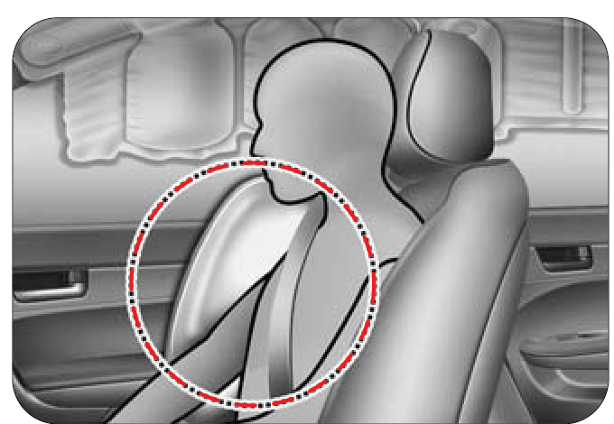
6.4 Curtain Airbag
Curtain air bags are located along both sides of the roof rails on the A & B pillars.
They are designed to help protect the heads of the front seat occupants and the rear outboard seat occupants in certain side impact collisions.
The curtain air bags are designed to deploy only during certain side impact collisions, depending on the crash severity, angle, speed and impact. The curtain air bags are not designed to deploy in all side impact situations, collisions from the front or rear of the vehicle or in most rollover situations.
- In order for side and curtain air bags to provide the best protection, both front seat occupants and both outboard rear occupants should sit in an upright position with the seat belts properly fastened. Importantly, children should sit in a proper child restraint system in the rear seat.
- When children are seated in the rear outboard seats, they must be seated in the proper child restraint system. Make sure to position the child restraint system as far away from the door side as possible, and secure the child restraint system in a locked position.
- Do not allow the passengers to lean their heads or bodies onto doors or place objects between the doors and passengers when they are seated on seats equipped with side and/or curtain air bags.
6.5 Airbag System Malfunction Lamp

Airbag’s do not require any regular maintenance of service. The airbag system malfunction lamp illuminates when the engine is started, and it turns OFF after about two seconds as self check confirming normal operations of airbag system and malfunction lamp.
This lamp monitors airbag sensor assembly, airbag sensors, indicator lamp, seat belt pre-tensioner's assemblies, inflators, interconnecting wiring and power sources.
If either of the following conditions occur, there is a malfunction of the airbag’s or seat belt pre-tensioner’s. Immediately contact your Mahindra dealer.
- The lamp does not glow when the ignition is switched ON or glows beyond six (6) seconds after switching the ignition ON
- The lamp comes ON at any other time, even briefly
Never make any modifications to your vehicle which could affect the performance of your airbag system. In particular, changes to the vehicle frame, bumpers, bull bar, front fenders, ride height, suspension, seat belts, interior trim, seats or steering wheel (especially covers, pads or other trim), could prevent proper deployment of the airbag. If you need to make any modifications to accommodate any disability you may have, please contact your authorized Mahindra dealer.
Never try to open or strike the airbag cover. If the airbag cover is cracked or damaged in any way, the airbag may not function as intended to. Take the vehicle to an authorized Mahindra dealer.
Even if the airbag’s do not deploy during an accident, take your vehicle to an authorized Mahindra dealer for a thorough inspection of the airbag and seat belt systems, no matter how minor the accident. The airbag system could have been damaged, and may not work as intended in a subsequent accident, resulting in serious injury.
6.6 Airbag Inflation/Deployment
The airbag sensors constantly monitor the forward deceleration of the vehicle. If an impact results in a forward deceleration beyond the designed threshold level, the system triggers the airbag inflators. The deceleration threshold level is low when the vehicle impacts straight into a fixed barrier that does not move or deform. This threshold deceleration will be considerably higher if the vehicle strikes an object, such as a parked vehicle or sign pole, which can move or deform on impact, or if the vehicle is involved in an underside collision. Once the deceleration level is met, a chemical reaction is triggered in the inflators which quickly fills the airbags with non-toxic gas.
Upon deployment, tear seams molded directly into the pad covers separate under pressure from the expansion of the air bags. Further opening of the covers allows full inflation of the airbag’s. A fully inflated air bag, in combination with a properly worn seat belt, slows the driver's or the passenger's forward motion, reducing the risk of head and chest injury.
After complete inflation, the air bag immediately starts deflating, enabling the driver to maintain forward visibility and the ability to steer or operate other controls.
Deployment of the airbag’s happen in a fraction of a second, producing a loud noise releasing smoke and residue along with a non-toxic gas. This does not indicate a fire. This smoke may remain inside the vehicle for some time, and may cause some minor irritation to the eyes, skin or breathing. Be sure to wash off any residue with soap and water as soon as possible to prevent any potential skin irritation. If you can safely exit from the vehicle, you should do so immediately.
- Do not modify, remove, strike or open the seat belt pre-tensioner assemblies, airbag sensor or surrounding area or wiring. Failure to follow these instructions may prevent them from activating correctly, cause sudden operation of the system or disable the system, which could result in serious injury.
- Parts of the airbag module (steering wheel hub, airbag cover and inflator) may be hot for several minutes after deployment. The airbag’s inflate only once.
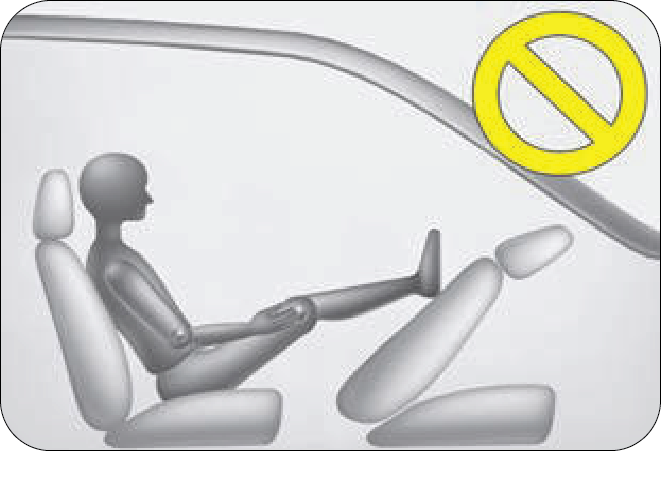
- Never place objects in front of you or on the dashboard while you are seated in the front seat. You could be injured by the object when it is forced toward you by the inflating airbag.
- Do not cover the steering wheel, instrument panel, seats with any object (e.g. dash panel covers, seat covers) which may prevent the airbag’s from inflating properly.
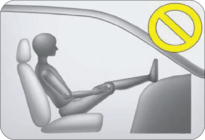
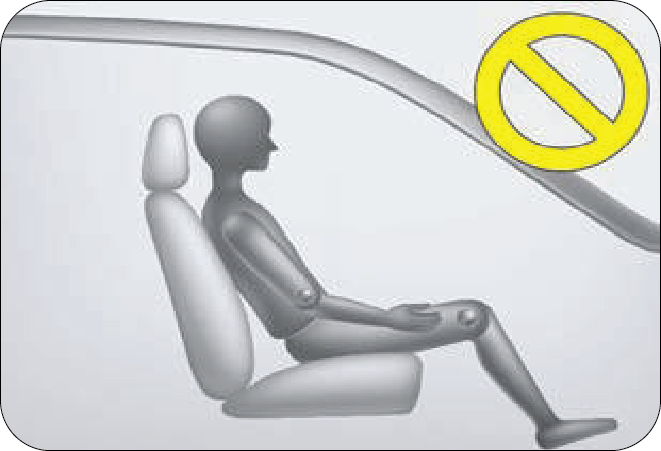
- The airbag’s inflate with considerable force. While the system is designed to reduce serious injuries, primarily to the head and chest, it may also cause other, less severe injuries to the face, chest, arms and hands. These are usually in the nature of minor burns or abrasions and swelling, but the force of a deploying airbag can also cause more serious injuries, especially if an occupant's hands, arms, chest or head is in close proximity to the airbag module at the time of deployment. Sit straight and well back into the seat. Move your seat as far back as practical to allow room for airbag inflation, while still allowing you to properly operate/drive the vehicle.
- The driver or front passenger who is too close to the steering wheel or dashboard can be seriously injured during airbag deployment.
- The driver must sit as far back as possible from the steering wheel while still maintaining control of the vehicle.
- The front passenger must sit as far back as possible from the dashboard.
- Sitting improperly or out of position can cause occupants to be shifted too close to a deploying air bag, strike the interior structure or be thrown from the vehicle resulting in serious injury.
- Always sit upright with the seat back in an upright position, on the seat cushion centre with your seat belt on, legs comfortably extended and your feet on the floor.
- All vehicle occupants must be properly restrained using the seat belts.
- All infants and children must be placed in the rear seat of the vehicle and be properly restrained by seat belts or in a child restraint system.
- Front and side air bags can injure occupants improperly positioned in the front seats.
- Even with air bags, improperly belted and unbelted occupants can be severely injured when the air bag inflates. Always follow the precautions about seat belts, air bags and occupant safety contained in this manual.
- Do not modify the front seats. Modification of the front seats could interfere with the operation of the supplementary restraint system sensing components or side impact air bags.
- Do not place items under the front seats. Placing items under the front seats could interfere with the operation of the supplementary restraint system sensing components and wiring harnesses.
6.7 Child Restraint and Airbag’s
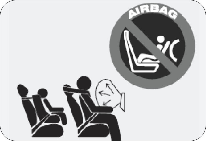
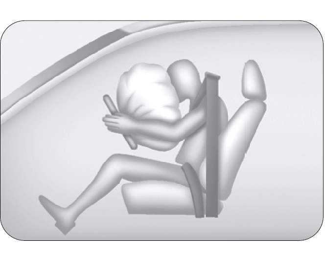
Extreme Hazard! Do not use a rearward facing child restraint on a seat protected by an air bag in front of it!
Never put a child restraint in the front passenger’s seat. If the front passenger air bag inflates, it can cause serious or fatal injuries.
- Never hold an infant or child on your lap. The infant or child could be seriously injured in the event of a crash. All infants and children should be properly restrained in appropriate child safety seats or seat belts in the rear seat.
- Install the child restraint system on the rear outboard seats, as far away as possible from the rear door, and securely lock the child restraint system in position.
- Inflation of side and/or curtain air bags could cause serious injury to an infant or child.
- ABC – Always Buckle Children in the back seat. It is the safest place for children of any age to ride.
6.8 Airbag Deployment and Non-Deployment
6.8.1 Airbag Deployment
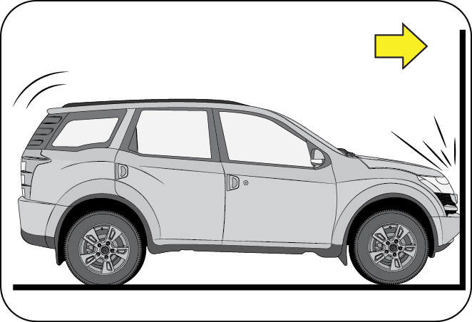
Front air bags are designed to inflate in a frontal collision depending on the intensity, speed or angles of impact of the front collision.
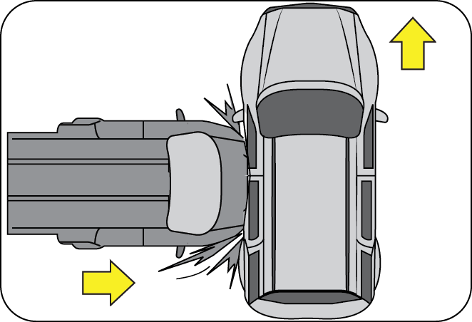
Side impact and curtain air bags are designed to inflate when an impact is detected by side collision sensors depending on the strength, speed or angles of impact resulting from a side impact collision.
Although the front air bags (driver’s and front passenger’s air bags) are designed to inflate only in frontal collisions, they also may inflate in other types of collisions if the front impact sensors detect a sufficient impact. Similarly, side impact and curtain air bags are designed to inflate not only in side impact collisions, but may inflate in other collisions if the side impact sensors detect a sufficient impact.
6.8.2 Airbag Non-deployment
Impacts below a pre-determined moderate threshold may not cause the airbags to deploy in the following cases:
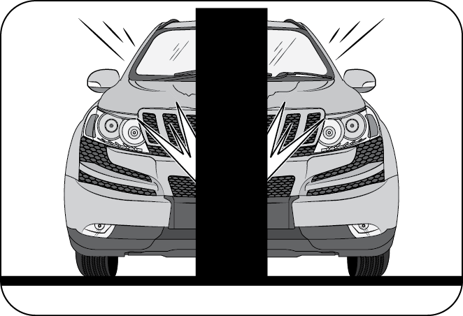
Air bags may not inflate if the vehicle collides with objects such as utility poles or trees, where the point of impact is concentrated to one area and the full force of the impact is not delivered to the sensors.
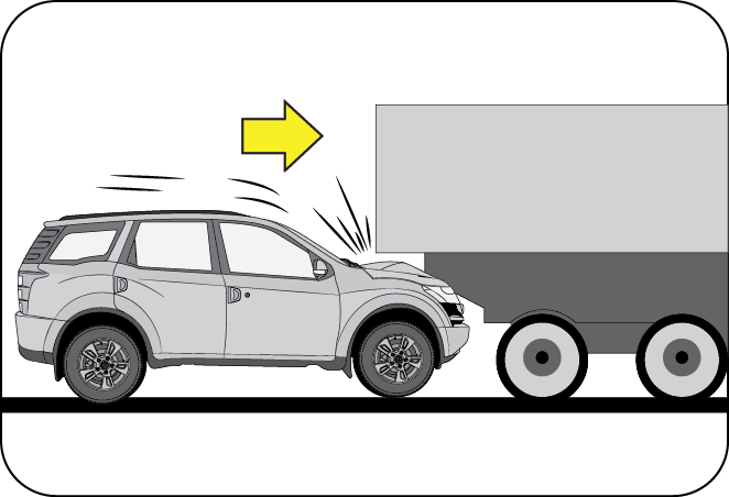
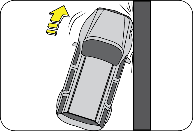
Running under a truck's tail gate may not provide the decelerations necessary for airbag deployment. Just before impact, drivers often brake heavily. Such heavy braking lowers the front portion of the vehicle causing it to “ride” under a vehicle with a higher ground clearance. Air bags may not inflate in this “under-ride” situation where deceleration forces that are detected by sensors may be significantly reduced by such “under-ride” collisions.
Frontal air bags are not designed to inflate in rear collisions, where occupants are moved backward by the force of the impact. In this case, inflated air bags would not be able to provide any additional benefit.

Frontal impact within 30º range from head-on to the vehicle.
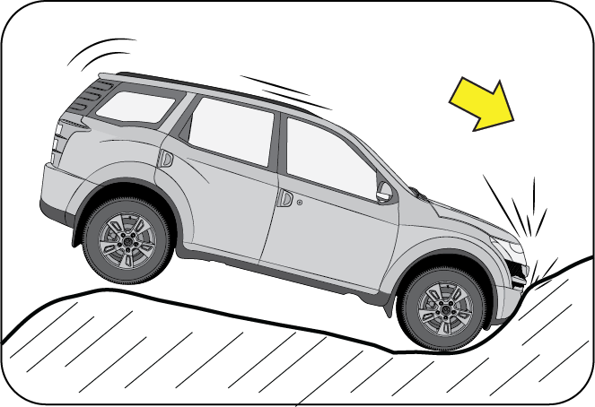
Driving into a big pot-hole, stepped surface or hitting the far side of a hole/incline will not inflate the airbag.
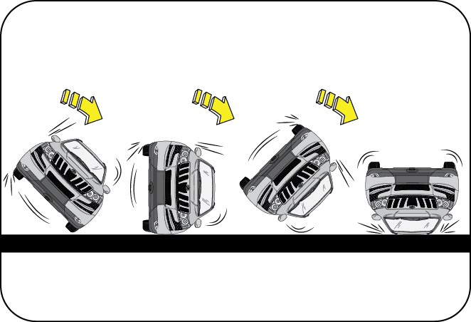
Air bags may not inflate in rollover accidents where air bag deployment would not provide protection to the occupants. However, side impact and curtain air bags may inflate when the vehicle is rolled over by a side impact collision.
Frontal Side Swipe impact to the vehicle may not provide the deceleration force necessary for airbag deployment. In an angled collision, the force of impact may direct the occupants in a direction where the air bags would not be able to provide any additional benefit, and thus the sensors may not deploy any air bags.
6.8.3 Airbag Replacement
An airbag will activate only once. Once activated, the airbag and sensors will not function again and must be replaced immediately
6.8.4 Self-Servicing or Repairing the Airbag System
Self-servicing or tampering with the airbag system is dangerous. An airbag could accidentally deploy causing serious injuries, or will not deploy when there is a need. Always take your vehicle to an authorized Mahindra dealer for inspection and repairs.
6.8.5 Removing SRS Related Parts
Removing the instrument panel, steering wheel, seats or parts containing airbag related parts or sensors is not recommended. Never attempt to remove or re-install these parts yourself or by any unauthorized persons. Airbags could accidentally activate and cause serious injuries, or they may not deploy when there is a need. Visit an authorized Mahindra dealer if these parts must be removed.
6.8.6 Airbag Disposal
Improper disposal of an airbag or a vehicle with live airbags can be extremely dangerous. Approach an authorized Mahindra dealer to do these jobs.
6.8.7 Airbag Repair
If the front airbag cover or IP airbag cover shows signs of damage or having been removed, the vehicle should be towed to the nearest authorized Mahindra dealer for repair. Do not attempt to self repair or reinstall the cover.
6.8.8 Airbag Maintenance
For cleaning the airbag covers/areas, use only a soft dry cloth or one which has been moistened with plain water. Solvents or cleaners could adversely affect the airbag covers and proper deployment of the system.
7 LOCKS AND KEYS
XUV500 comes with two keys. Your key number is given on the tag attached to the key. It is recommended that you record the key number and store in a safe place. The keys operate all locks in your vehicle including those of the doors and ignition with steering lock. We advise you to keep one of these keys at a safe place for emergency use, but not in the vehicle.
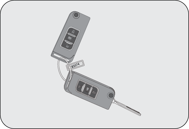
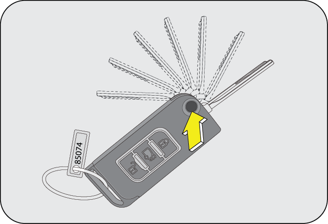
Press the key release button on the RKE to unfold the key.
Never leave the key in the ignition switch with children in the vehicle. A child could switch on the ignition, start the engine, operate power windows and other controls, or move the vehicle, resulting in personal injuries to the bystanders and/or children seated inside.
7.1 Doors
7.1.1 To Open a Door from Inside
Pull the door lever away from the door and push the door outward to open.
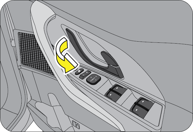
7.1.2 To Open a Door from Outside
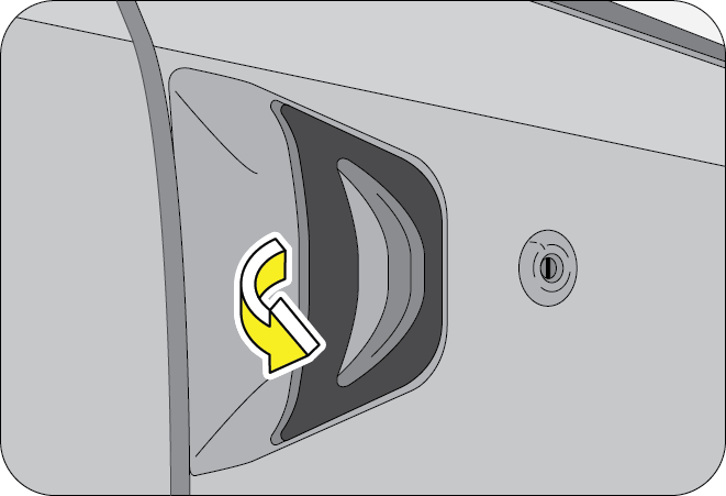
Pull the door handle firmly outwards to unlock and swing the door open.
7.1.3 Locking/Unlocking Individual Doors from Inside
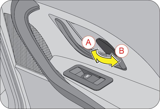
| A | Lock | B | UnLock |
Individual doors can be locked/unlocked from inside by the respective door lock tabs. Lift the lock tab outwards to unlock or press the tab inwards to lock that particular door.
Locking the driver door from inside activates the central locking system, thereby locking ALL the doors of the vehicle. Refer to Central Locking section for further details.
7.1.4 Manual Locking/Unlocking Doors from Outside
The driver/co-driver door can be manually locked/unlocked from outside by using RKE. Open the key by pressing the key release button on the RKE. The key is bi-directional; you can insert it into the key hole either way. Turn the key anticlockwise to lock or clockwise to unlock the door.
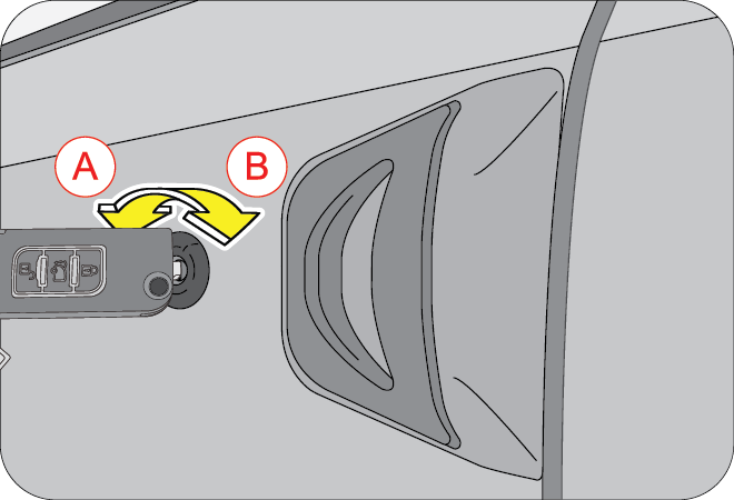
| A | Lock | B | UnLock |
A key hole is provided in the driver door and front passenger door, to lock/unlock the doors manually from outside.
Locking the driver door from outside activates the central locking system, thereby locking ALL the doors of the vehicle. Refer to Central Locking section for further details.
7.1.5 Locking/Unlocking the Back Door
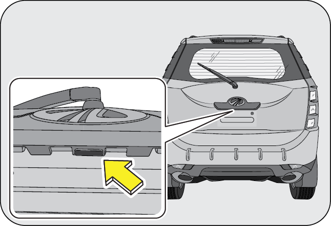
The back door can be manually unlocked by pressing the unlock button under the rear applique.
To close the back door, lower the back door half way down and allow it fall on its own weight. The door is locked automatically
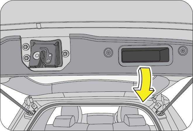
7.2 Central Locking System
All doors of the vehicle can be simultaneously locked or unlocked from the driver door.
7.2.1 Central Locking/Unlocking All Doors from Outside
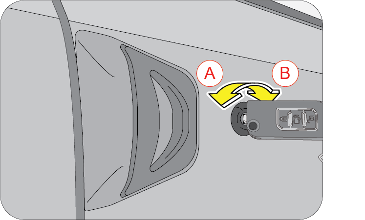
To manually lock/unlock all the doors from outside using the RKE, turn the key anti-clockwise (A)/clockwise (B) respectively in the driver door key hole.
In case the back door is open when the central locking is activated, the back door will not be locked even if it is closed later.
If any other door is open when central locking is activated, the system locks the open doors when they are closed.
7.2.2 Central Locking/Unlocking All Doors from Inside
Press the driver door lock tab down (A) to lock or lift the lock tab up (B) to unlock all doors simultaneously.
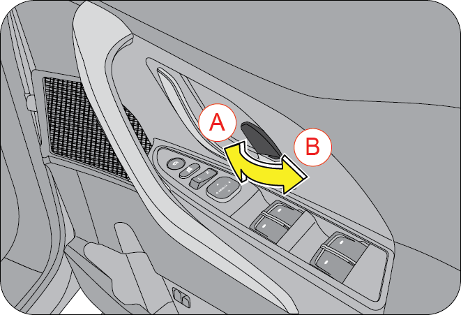
7.2.3 Child Safety Rear Door Lock
Your vehicle is equipped with left and right side child safety rear door locks. When the lock mechanism is engaged, the rear door(s) cannot be opened from the inside. The door(s) can only be opened from the outside.
To activate the child safety right rear door lock push the lever down (A) till you hear a distinct click indicating the activation of the child lock.
To de-activate the child safety right rear door lock pull the lever up (B) till you hear a distinct click indicating the deactivation of the child lock.
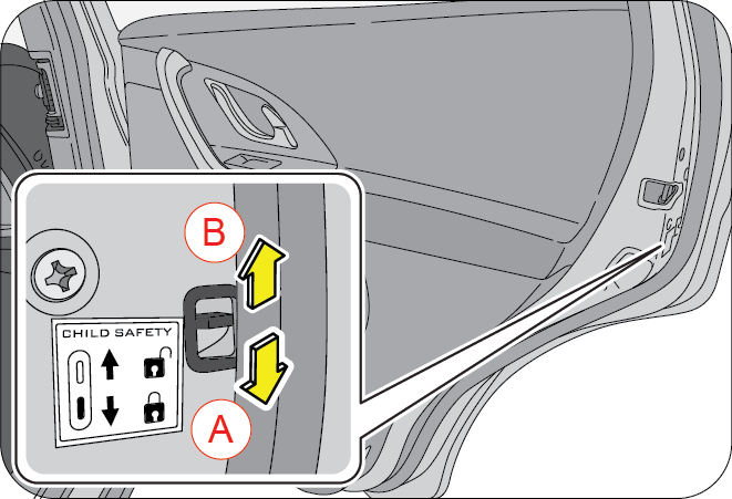
| A | Activate/Lock | B | De-activate/Unlock |
If the rear doors are not operable from inside, ensure that the child safety locks have been disabled.
Mahindra strongly recommends that the child safety rear door locks be used whenever there are children traveling in the rear seat.
7.3 Remote Keyless Entry (RKE) System
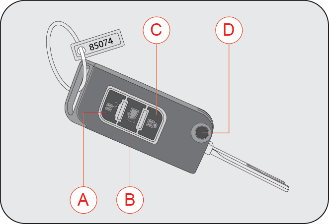
| A | Unlock Button | C | Lock Button |
| B | Back Door Open Button | D | Key Release Button |
The front side of the RKE has three control buttons; Unlock, Lock and Search buttons. There is also a mechanical key release button (D). The Remote Keyless Entry (RKE) system operates on Radio Frequency (RF). You can insert the key into the ignition with either side up.
7.3.1 Precautions while handling RKE:
- Do not cover the key grip with any material that cuts off RF waves
- Do not leave the key exposed to high temperatures for a long period, such as on the dashboard or hood under direct sunlight
- Do not put the key in any liquid or wash it in an ultrasonic washer
7.3.2 To Lock and Arm the Vehicle with RKE
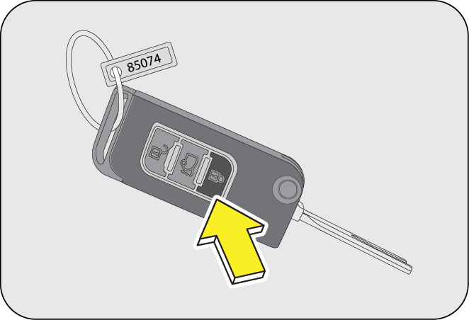
Press the lock button on the RKE for locking and arming the vehicle. When the vehicle is successfully locked and armed using the RKE, the hazard lamps flash once. If there are any open doors, the hazard lamps flash five times along with audible beeps indicating the same.
The audible beeps heard during the door open status can be muted/unmuted by pressing the lock button on the RKE for more than 3 secs.
- If any of the doors, except the driver door, are open while locking the vehicle with RKE, the vehicle locks all doors (door locks) irrespective of the open door/doors. When the open door(s) is/are closed later, the vehicle is locked and armed.
- If the driver door is open while locking the vehicle with RKE, the vehicle is not locked or armed. Close the driver door and lock the vehicle again with RKE to arm the Anti-theft system.
7.3.3 Unlock and Disarm the Vehicle with RKE

Press the unlock button on the RKE to unlock and disarm the vehicle. When the vehicle is unlocked and disarmed using RKE, hazard lamps flash twice
7.3.4 Theft Alarm
If there was an unauthorized attempt to open/start the vehicle by someone from the time you had locked and armed the vehicle to the time you press the unlock button of RKE, the hazard lamps flash four times along with an alarm indicating the attempt. If this occurs, press the “UNLOCK” button on the RKE to disarm the security alarm.
Using the ignition key to open the door, when the vehicle was locked and armed with RKE will be treated as unauthorized by the system setting off the alarm.
When vehicle is armed by RKE, opening the door from inside by operating the door inner handle will activate the vehicle theft alarm.
Press the unlock button on the RKE to cancel the alarm.
7.3.5 Back Door Open
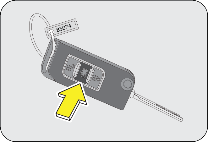
Press the back door open button on the RKE to unlock the back door. The hazard lamps flash four timesindicating the same.
7.3.6 Search Function
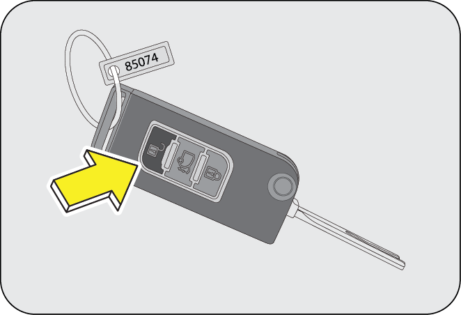
The search function can be used to locate the vehicle in a parking lot. Press the unlock button on the RKE for more than 3 sec. continuously to activate the search function
When the Search function is ON, the hazard lamps flash for approx. 30 sec. helping you to locate your vehicle. To extend the search, press the search button again which will flash the hazard lamps for another 30 sec. You can turn it OFF by pressing the unlock button.
The head lamps also turn ON when UNLOCK button is pressed twice (enabling the LMV feature). For the first UNLOCK command, the doors are unlocked, and for the next UNLOCK command, the head lamps turn ON enabling you to safely board/locate the vehicle in the night.
Search function works both during Locked/Unlocked conditions of the vehicle.
7.3.7 Mute/Un-mute the Alarm/Beeps

The alarm or beeps heard when one of the doors are open can be muted/un-muted. Press the lock button for more than 3 sec. to swap between mute and un-mute.
The beeps heard during the door open situation can be muted/unmuted. There are NO BEEPS during normal locking/unlocking of doors.
7.3.8 Panic Alarm Function

The panic alarm function can be used during emergencies to draw the attention of onlookers/bystanders. Press the unlock button on the RKE for more than 3 sec. continuously when the key is in the ignition to activate the panic alarm.
7.3.9 Auto Locking
When the vehicle crosses 20 kmph road speed range with all the doors closed properly, all doors are locked automatically.
7.3.10 Auto Unlocking
All the doors are unlocked automatically, when the vehicle has halted and ignition switched OFF. If the ignition is not switched ON for the next few seconds, all the doors are locked due to auto locking, provided doors are not open.
7.3.11 Auto Re-locking
Once you press the unlock button on the RKE, if you do not open any of the doors for the next 45 sec., all the doors are re-locked automatically.
In case of an accident/collision where a SRS has been activated (Eg. airbag), all the doors are unlocked automatically.
7.3.12 RKE Operating Range
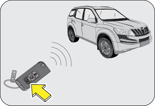
Using RKE, you can lock/arm or unlock/disarm the vehicle from distances approx. 30ft.(9m).
If there is reduction in RKE range, please follow the steps below:
- Check the distance: The RKE may be too far from the vehicle. Stand closer to the vehicle during rain or bad weather
- Check the location: Other vehicles or objects may be blocking the signals. Take a few steps to the left or right, hold the RKE higher, and try again. Moreover, closeness to a radio transmitter such as radio station tower, airport transmitter, mobile or CB radios may lead to reduction in range of RKE
- Check the RKE battery: See battery replacement procedure, given later in this section
- If the RKE is still not working correctly, contact an Authorized Mahindra Dealer
7.3.13 RKE Battery Replacement
If the RKE operation is inconsistent when any of the buttons are pressed it indicates that the RKE battery is weak. The rear side of the RKE is snap fitted. Using a small screw driver or similar tool, pry or separate the two halves of the casing.
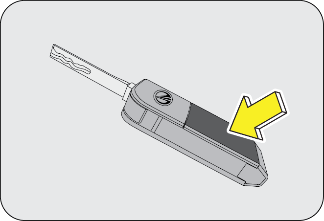
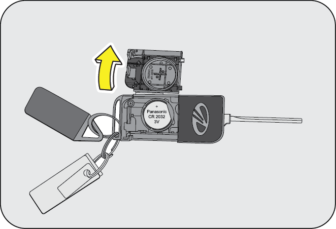
Pull out the batteries and discard the same. Insert two new batteries of 3V type. While fitting the new battery, ensure the positive side of the batteries face up. Align both the halves of the RKE and press to snap fit. Check operation of the RKE.
While prying the RKE case, take care not to damage the battery. Do not touch the battery terminals or contacts.
Do not mix old batteries with new batteries. Replace BOTH the batteries when the RKE operation is weak.
Perchlorate material needs special handling and disposal. Refer to local regulations.
7.3.14 If RKE is Lost
If you have lost the programmed RKE, contact an Authorized Mahindra Dealer for procuring a new RKE.
While programming a new key set, you will have to submit all the keys available with you, to an Authorized Mahindra Deale
Please note that there is a limitation (max 2 keys at a time) to the number of keys that can be ordered. The minimum time frame required to supply the duplicate keys is 10 days after all the formalities are completed. Please contact the dealer to understand the formalities involved.
If you make your own duplicate key, you will not be able to deactivate the anti-theft devices or start the engine.
If the key is stolen or lost, communicate to Authorized Mahindra Dealer for de-activating the function of the lost or stolen key. This is essential to avoid unauthorized access using the misplaced key.
Only RKE transmitters programmed to your vehicle electronics can be used for remote locking and unlocking of your vehicle.
7.4 Engine Immobilizer System

An Engine Immobilizer System is a security system that prevents the vehicle being operated by an unauthorized person. The Engine immobilizer prevents the engine from being started unless it recognizes signals from the correct coded key. When a wrong key is inserted or a theft attempt is detected, the alarm is set off, and the hazard lamps flash along with a siren.
The system is automatically activated when the key is removed from the ignition.
7.4.1 Features of the Immobilizer System:
- Prevents the vehicle being started by anyone not in possession of the correct vehicle key
- The vehicle is automatically protected after the key is removed from the ignition. At every ignition ON, if the vehicle does not recognize the correct key code, the engine check lamp will be illuminate/blink and the engine cannot be started
- The vehicle will not be protected until the key has been taken out of the ignition
If the engine check lamp flashes or remains continuously illuminated after the ignition being switched ON, there is a system malfunction. Contact an Authorized Mahindra Dealer immediately.
Inserting the correct coded key in the ignition and switching the ignition ON, automatically deactivates the system. This enables the engine to start.
In the event of the vehicle not starting with the correct key, switch off the ignition for a minimum of 1 minute and attempt to start the vehicle again.
Do not modify, remove or disassemble the engine immobilizer system. Any unauthorized changes or modifications can affect proper operation of the system and will void your warranty.
The security system will be activated only when the vehicle is locked using the RKE. Locking the doors with the manual key will not activate the security system.
Using the ignition key to open the door, when the vehicle was locked and armed with RKE will be treated as unauthorized by the system setting off the alarm. Press the unlock button on the RKE to cancel the alarm.
8 FEATURES AND CONTROL
8.1 Quadruple Switch
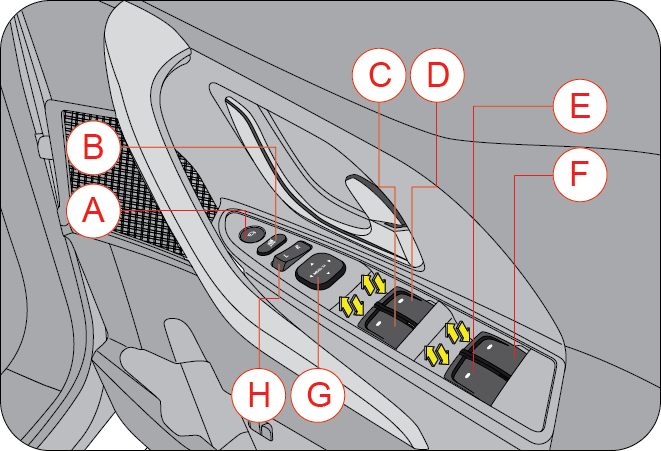
| A | ORVM Fold Switch | E | Rear LH Window Switch |
| B | Power Window Lock | F | Rear RH Window Switch |
| C | Front Passenger Window | G | ORVM Perimeter Switch |
| D | Driver Door Window | H | ORVM Selector Switch |
The quadruple power window switch on the driver door armrest/handle controls the following functions;
- Both LH and RH ORVM folding
- ORVM selector
- ORVM adjustment
- Power window functions of all doors in the vehicle.
- Power window safety switch that enables/disables power window operation of other doors when operated independently from the respective doors
8.1.1 Power Windows
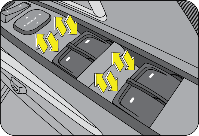
Power windows can be operated only when the ignition is “ON” position. The driver can operate all the power windows in the vehicle through the quadruple switch on the driver door armrest/handle. Other passengers in the vehicle can raise or lower their respective window glasses individually by using the separate switches provided on each of the door trim pads/arm rests.
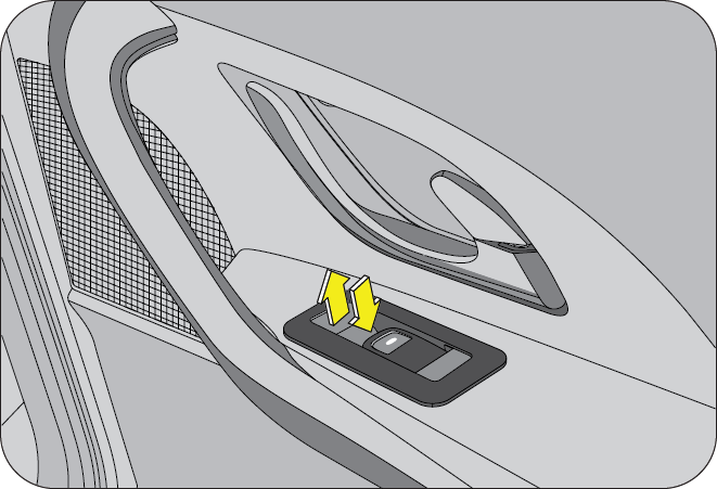
To lower/raise the window glass push/pull the power window switches respectively.
Do not operate the power windows frequently when the engine is OFF. This will drain the vehicle battery.
If you operate the switches often during a short period of time, the system might become inoperable for a certain duration to prevent damage due to overheating. The system will return to normal functioning shortly. It is recommended to operate one window switch at a time.
While operating the power windows, check for obstructions like head, hand, etc. which may lead to personal injuries.
8.1.2 Power Window Lock Switch
The main power window quadruple switch in the driver door trim has a power window lock switch to enable or disable operation of rear passenger and front passenger window switches. To disable the rear or front passenger power windows, press the window lock switch down. To revert to normal operation, press the window lock switch again. 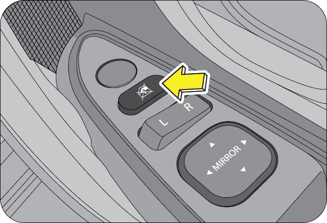
8.1.3 Auto/Express DOWN (driver side only)
Press the driver power window switch down for a moment and release. The glass moves all the way down automatically. You do not need to hold the switch till the glass comes down.
8.2 Mirrors
8.2.1 Manual ORVM (if equipped)
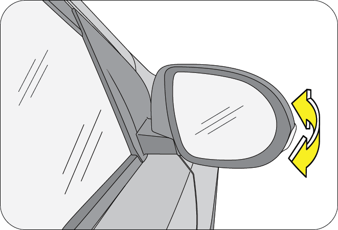
Integrated exterior rear view mirrors on both the sides facilitate maximum rear view information to the driver.
Fold both the ORVM’s manually while parking the vehicle in congested roads or narrow parking slots. This avoids hindrances and safeguards the ORVM’s.
8.2.2 Electric ORVM (if equipped)
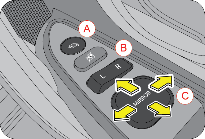
| A | ORVM Fold Switch | B | ORVM Selector Switch |
| C | ORVM Adjustment Switch (4-way) |
The ORVM fold switch, ORVM adjustment switch (perimeter switch) and the Left (L)/Right (R) ORVM selector switches are located on the driver door trim/handle.
Both the ORVM’s can be electrically folded or unfolded by the pressing the ORVM fold button (A).
All ORVM controls work only when ignition is ON or engine is in running condition.
The electric ORVM’s fold automatically when the vehicle is locked through RKE or unlocked through RKE and ignition switched ON.
The ORVM folding/unfolding operation is limited to 2 times / minute.
Do not overestimate the distance of the objects that you see in the mirrors. Objects seen in convex mirrors are much closer than they appear.
Use the ORVM L/R selector switch, to select Left/Right side exterior mirror respectively. The ORVM adjustment switch adjusts the selected ORVM in the required direction. Lock the ORVM’s by setting the ORVM selector switch to the middle position.
8.2.3 Interior Mirrors
There are two interior mirrors, one is a conversation mirror (fish eye type) and other interior rear view mirror.
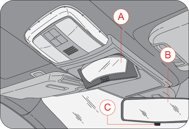
| A | Conversation Mirror | B | Interior Rear View Mirror |
| C | Day/Night Adjust Tab |
8.2.4 Conversation Mirror
The conversation mirror can be used to converse with the rear passengers in the vehicle. Press the mirror cover to lower the conversation mirror. Close the mirror back and press to lock the mirror in position.
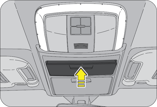
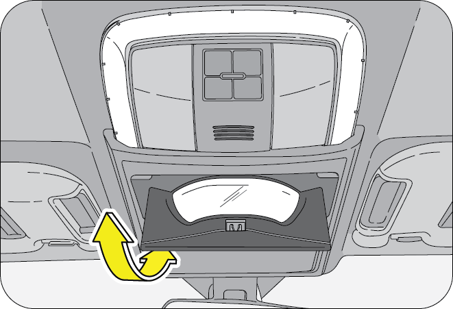
8.2.5 Interior Rear View Mirror
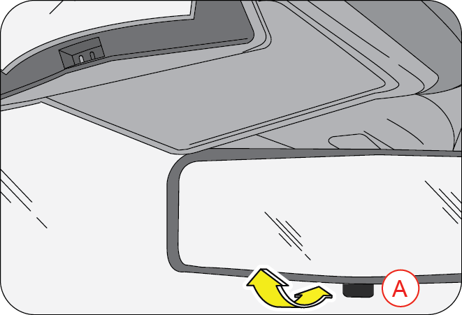
The interior rear view mirror provides the rear view information to the driver and also aids during reversing.
This mirror has day and night (anti-glare) positions. The night position reduces glare from head lamps of vehicles behind you. Flip the tab (A) on the bottom edge of the mirror to select the day or night position.
8.3 Sun Visor
Sun Visors are provided for both driver and co-driver above the windshield. The sun visors can be used for either frontal or sideward shade, to reduce glare or to shut out direct rays of the sun.
Pull down the sun visor to block the glare of the sun. The sun visor can also be swivelled to the side as shown.
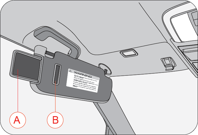
| A | Sun Visor Extension | B | Ticket Holder |
A illuminated vanity mirror (in export variants only) is provided on the back of both the driver and co-driver sun visors. Slide the flap/cover to access the mirror. The lamp (A) above the sun visor illuminate automatically when the flap is opened and switch OFF when flap is closed.
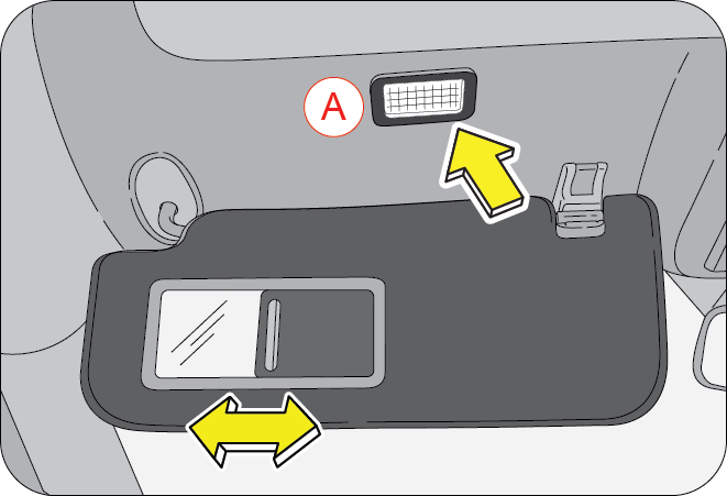
The vanity mirror lamp will remain ON as long as the mirror flap/cover is open. This may lead to battery drain if left unchecked for long durations. Ensure the mirror flap/cover is always closed properly before folding back the sun visor in its position.
8.4 Utility Holders
8.4.1 Upper Console Tray
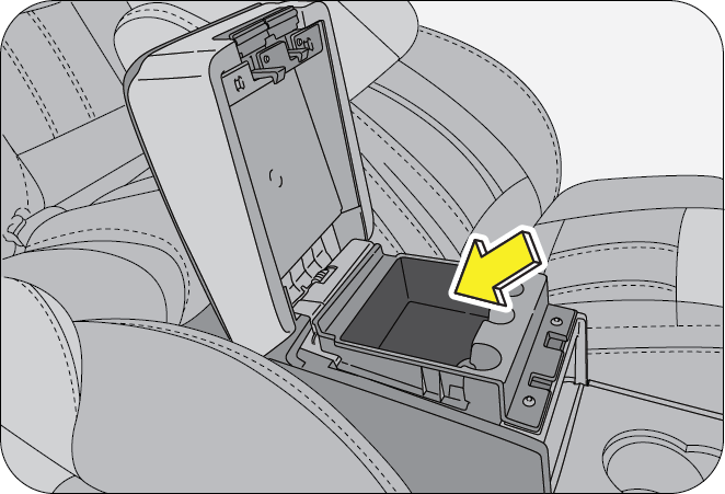
Do not place large or heavy objects on the foldable trays, accessing the centre console storage will be difficult. Ensure the tray cover is latched properly once closed.
Unlock the console tray cover by unlocking the tray latch (A) and lifting the cover all the way up.
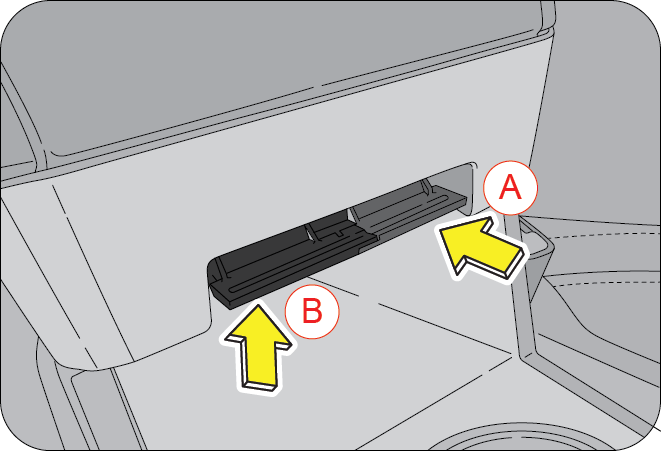
| A | Upper Console Tray | B | Centre Console Storage |
8.4.2 Centre Console Storage/Cooler (if equipped)
Bigger objects, cans, etc., can be stored in the centre console storage. Unlock the centre console cover (which includes the upper tray console also) by unlocking the latch (B) and lift the console cover all the way up.
In select variants a cooler (air vents) is provided in the centre console storage. You can cool cans, small bottles, etc,. by opening the air vents at the bottom floor of the storage. Turn the cooler clockwise to open the air vents, or anti-clockwise to close the air vents.
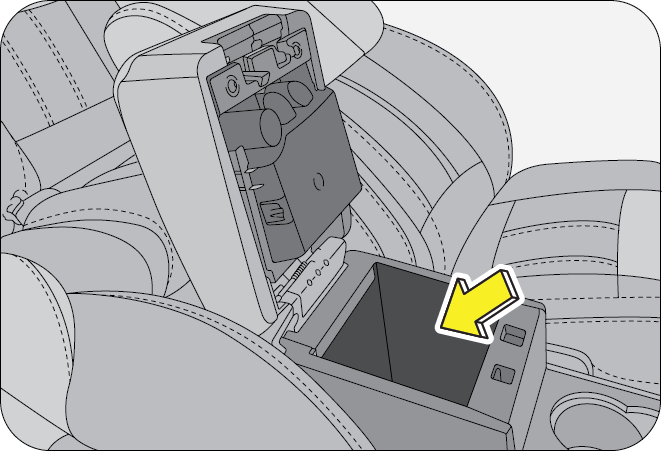
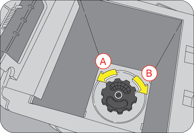
| A | OFF | B | ON |
Only sealed cans/bottles to be stored in the centre console storage/cooler. Any spilled beverage can damage the interior trim and electrical components/cooler.
8.4.3 Multi-box Storage
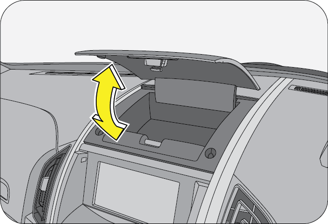
The multi-box is located above the infotainment screen in the centre console. It can be used for storing small items like mobiles, wallets, tickets, etc.
To open the lid, gently press the lid. To close, gently press the lid all the way down till it locks.
Do not store big items in the multi-box which may obstruct the proper closure of the multi-box lid. On rough or uneven roads, the lid might open up spilling the contents and leading to distraction.
8.4.4 Centre Box
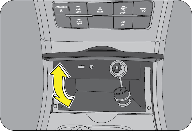
The centre box is located below the HVAC/Switch bank near the gear lever. Small objects like tickets, wallet, etc., can be stored. To open, gently press the centre box lid. To close, gently press the lid all the way down till it locks.
8.4.5 Glove Box
There are two glove boxes on the co-driver side of the instrument panel.
- Upper Glove Box
- Lower Glove Box
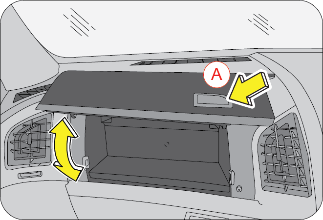
The upper glove box can be opened by gently pressing the unlock push button (A). To close, gently lower the glove box lid and press to lock.
Do not overload the glove box.
Do not store loose or small metal objects inside glove box. This will lead to rattling while the vehicle is driven on bad roads.
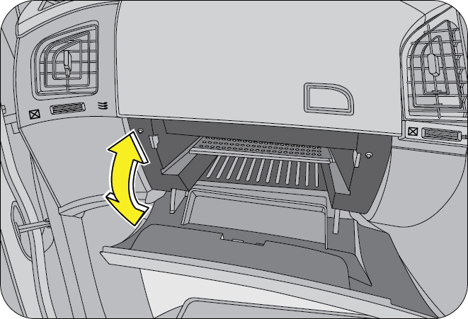
The lower glove box is located just below the upper glove box. To open, gently press the unlock push button, and lower the lid. To close the glove box, raise the lid all the way up and gently press to lock the lid.
The lower glove box is illuminated automatically when it is opened and the light turns OFF when it is closed.
It is suggested to keep copies of all vehicle documents along with the owner’s manual kit in the glove box for reference when needed.
To avoid the possibility of injury in case of an accident or a sudden stop, both the upper and lower glove box lids should be kept closed when the vehicle is in motion.
8.4.6 Cup Holder
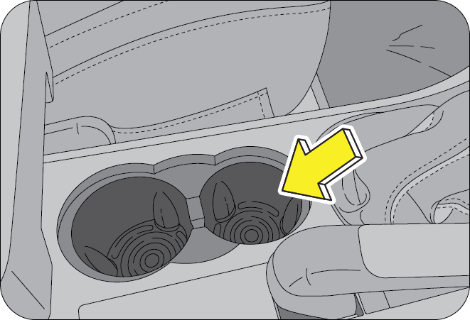
The cup holder located in the floor console between the front seats, It can be used for small cups or cans that are closed or have a lid.
Only sealed cups/cans with lid to be used in the cup holders.
Use caution when using the cup holders. A spilled beverage that is very hot can injure driver or passengers. Spilled liquids can also damage interior trim and electrical components. Any spilled beverage can also startle the driver and cause a loss of control of the vehicle resulting in an accident.
An ash tray is provided in the cup holder. Lift the lid to use the ash tray. To empty the ash tray, firmly pull the ash tray up. Similarly, to put it back, gently press the ash tray back in the same location.
Do not use the ashtray for disposing of waste paper or other combustible items. They may catch fire when a cigarette butt is extinguished in the ash tray.
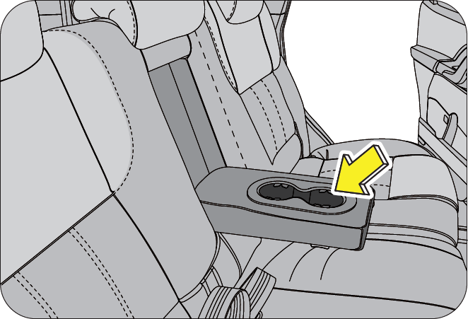
The second rows seats have an armrest embedded into the seat back. The arm rest can be unfolded and used as a cup holder.
Only sealed or cups with lid and cans to be used in the cup holders.
Use caution when using the cup holders. A spilled beverage that is very hot can injure the passengers. Spilled liquids can also damage interior trim. Never place objects other than cups or cans in the cup holder. These objects can be thrown out in the event of a sudden stop or an accident, possibly injuring the passengers in the vehicle.
The second rows seats have an armrest embedded into the seat back. The arm rest incorporates a storage bin with smooth operating magnetic bin cover and a cup holder.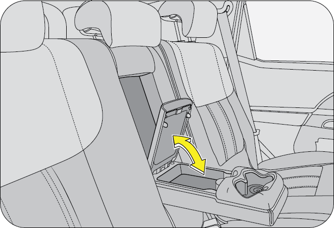
The second rows seats have an armrest embedded into the seat back. The arm rest incorporates a storage bin with smooth operating magnetic bin cover and a cup holder.
Only sealed or cups with lid and cans to be used in the cup holders.
Use caution when using the cup holders. A spilled beverage that is very hot can injure the passengers. Spilled liquids can also damage interior trim. Never place objects other than cups or cans in the cup holder. These objects can be thrown out in the event of a sudden stop or an accident, possibly injuring the passengers in the vehicle.
8.4.10 Third Row Cup Holder
The cup holders are located on both left and right side trims below the magazine holder.
Only sealed or cups with lid and cans to be used in the cup holders.
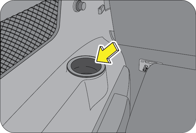
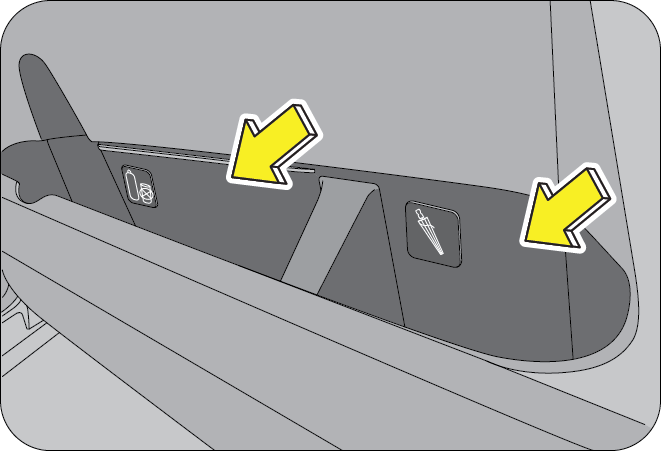
Bottle and Umbrella holders are located on both the front door lower trims. You can use them to store umbrellas, maps, papers, small books, bottles, etc.
Only sealed/closed bottles are to be used in the bottle holders.
The seat back pockets are located on the back of the front seats for holding light weight papers/books/magazines, etc.
To avoid injury, do not place large or hard objects in the seat back pockets. Do not put more than 1 Kg weight in seat back pockets.
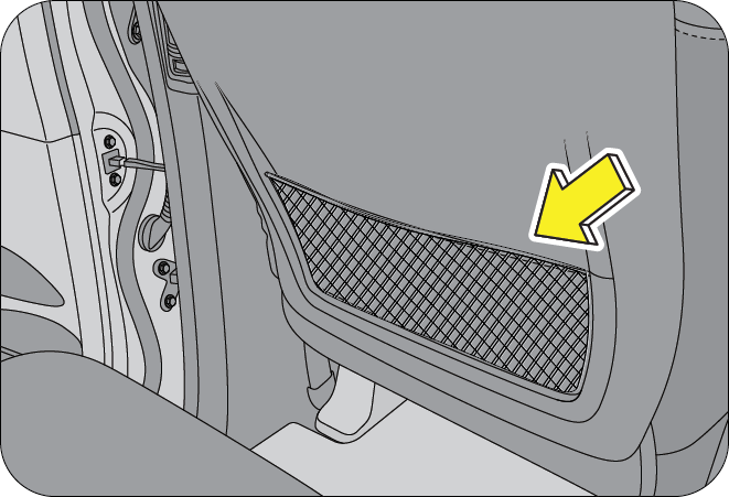
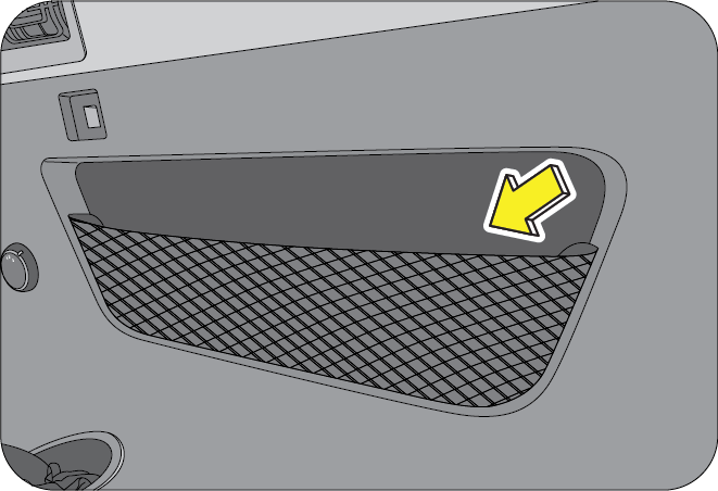
The third row magazine pockets are located on the trims on either side of the third row seats. They can be used for holding light weight papers/books/magazines, etc.
Do not place large or hard objects in the magazine pockets. Do not put heavy objects in the magazine pockets.
There are two ticket, mobile or small object holders on either side of the front floor console.
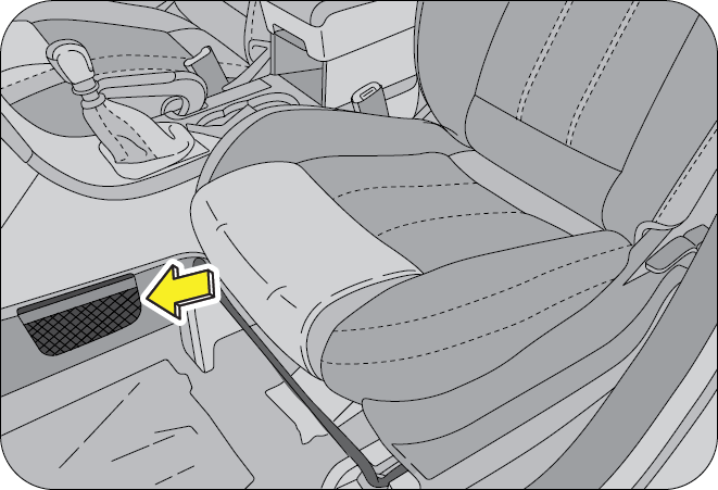
8.4.14 Grip Handle
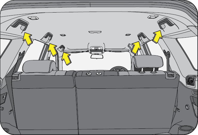
Foldable grip handles are provided above the front (passenger only), second row and third row outboard seats.
8.4.15 Coat Hook
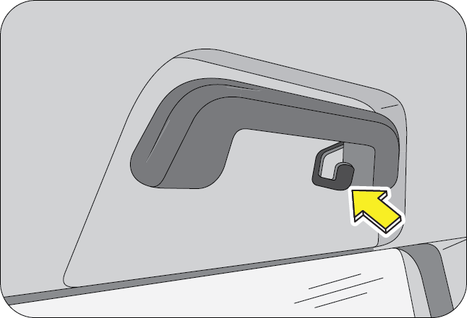
The second row outboard passenger seats grip handles feature a coat hook for hanging your coat, shirts, etc.
Hang light weight articles only. Hanging excess/bulky weight/items may cause breakage of the hook and inconvenience to the passengers.
8.4.16 Sun Glass Holder
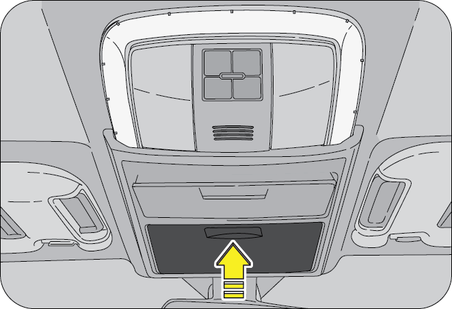
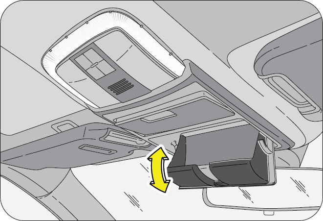
Roof mounted sun glass holder is integral part of the front interior lamp. Press the lid to release the latch and lower the holder. It is strategically positioned to be accessed easily by both the driver and front passenger.
Do not access the sun glass holder while you are driving. It may distract your concentration and could lead to an accident.
8.4.17 Floor Mat (if equipped)
Floor mats are provided in the front and rear foot wells to avoid stains on the floor carpet.
Always keep the floor mats in their correct position to avoid interference with the movement of the accelerator or brake pedals during driving, which may lead to accidents.
8.5 Horn
Press the pad on the steering wheel to blow/sound the horn. The horn functions even when the ignition has been switched OFF.
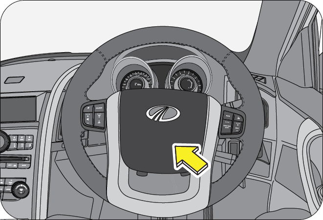
8.6 Interior Lamps
Interior lamps comprise of front/rear roof lamps, map reading lamps, ambience lamps and ignition key ring illumination. These lamps can be used for an illuminated entry. In auto mode, the roof lamps (courtesy lamps) and ignition key ring illuminate when any of the doors are opened. Once all doors are closed, the interior lamps switch OFF.
8.6.1 Front Roof Lamp
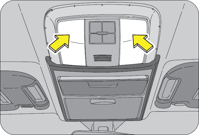
The front roof lamps are located in the roof console above the interior rear view mirror. The roof lamp can be switched ON pressing the lens on the lamp. Press the lens again to switch OFF the roof lamp
8.6.2 Map Reading Lamp (if equipped)
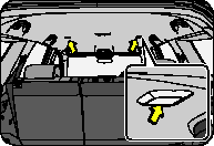
Do not leave the roof/map reading lamp in permanent ON mode. This will drain your vehicle battery.
8.6.3 Second Row Roof Lamp
The second row roof lamp is located on the roof above the second row seats. The courtesy lamp can be switched ON/OFF by the switch on the lamp.
The roof lamp switch has three operation modes to choose from
- The roof lamp remains permanently ON in this position irrespective of the door open status
- The roof lamp remains in DOOR/AUTO mode in this position.
- The roof lamp remains permanently OFF in this position
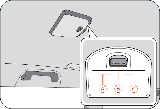
| A | Permanent ON | C | Permanent OFF |
| B | Door/Auto Mode |
The operation of the roof lamp in door mode is as follows:
- Roof lamp switches ON, dims and goes OFF after 10 sec delay during RKE unlock
- Roof lamp switches ON when any of the doors is/are open
- Roof lamp dims and goes OFF after 10 sec delay upon closing of all doors
- Roof lamp dims and goes OFF immediately on RKE lock after all doors are closed
- If any of the doors are not closed properly, the roof lamp switches OFF automatically after a preset duration
- Roof lamp goes OFF with ignition ON and all doors closed properly
The roof lamp will be turned ON in the case of an accident in a SRS equipped variant provided the roof lamp switch is in “Door” mode.
8.6.4 Ambience Lamp (if equipped)
The ambience lamps give out a light red ambience in the vehicle. They can be switched ON/OFF by the ambience button on the centre bezel switch bank.
Ambience lamps are located in the following locations
- Around the front roof lamp
- Under the seat
- Above the pedals in the driver side foot well
- Below the door handle
- Above the bottle holder in the inner door trim
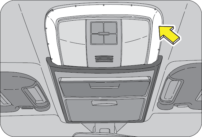
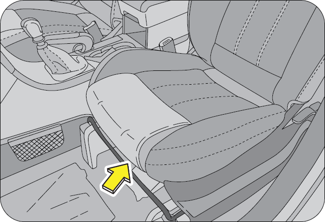

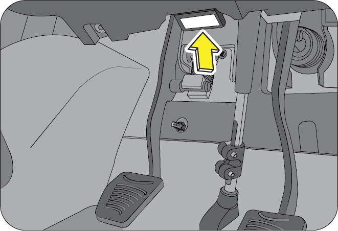
8.6.5 Door Ajar Lamp (if equipped)
The door ajar lamp illuminates even in the vehicle switched OFF condition with the ignition key removed.
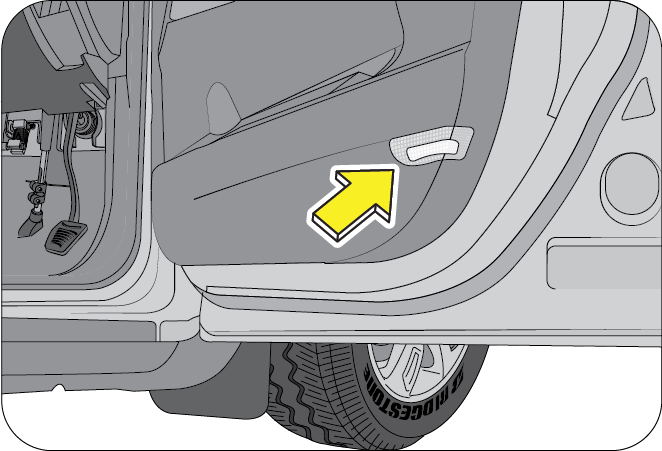
8.6.6 Camping Lamp (if equipped)
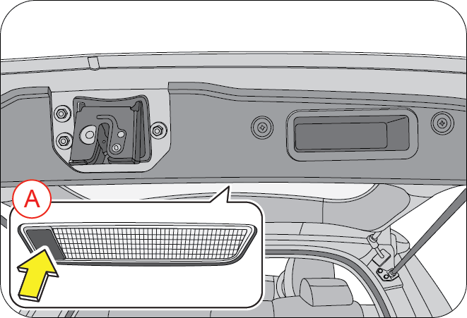
Camping lamp aids you during brief stops in night trips and also while loading/unloading luggage in the rear. It is switched ON/OFF by pressing the switch (A) on the camp lamp.
8.6.7 Battery Saver
The battery saver feature helps in switching OFF interior lamps that are inadvertently ON for long durations. This feature works only after the vehicle is locked with the interior lamp ON. If the vehicle is improperly closed/locked, the battery saver switches OFF the lamp after a duration of 3 mins.
8.7 Power Outlet
There are three (depends on the variant) 12V power supply sockets provided for power take OFF. Electrical equipment/appliances like mobile phone charger, cigarette lighter, etc. can be used in the outlets.
The power outlets are located in the following places in the vehicle
-
Front - In the compartment below the centre bezel switch bank.
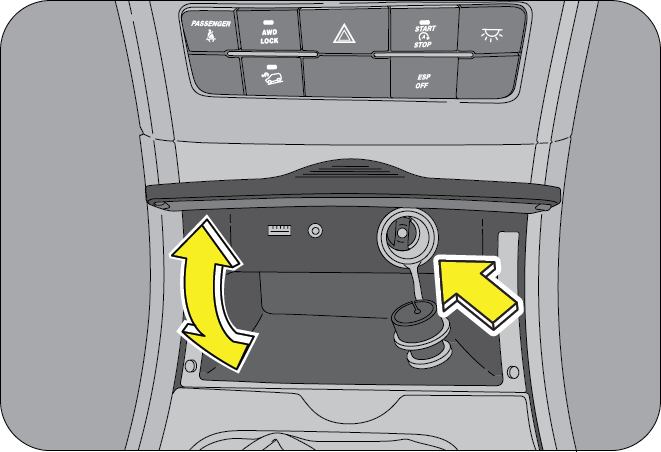
-
Second Row - Behind the centre console storage (if equipped)
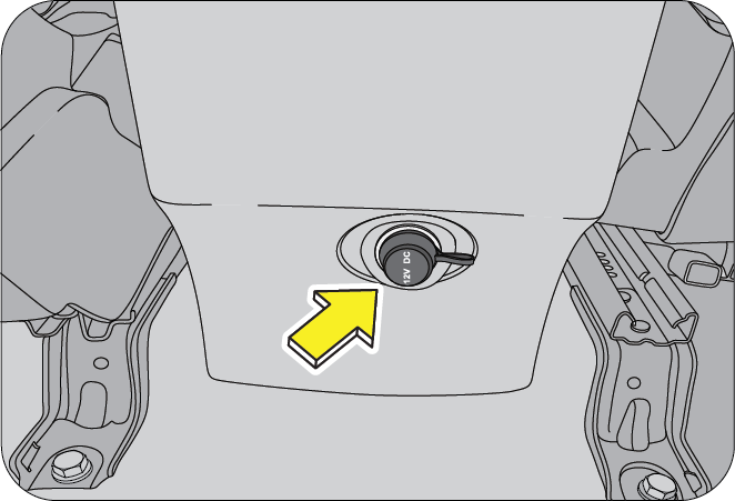
-
Third Row - Below the manual fuel lid open knob (if equipped)
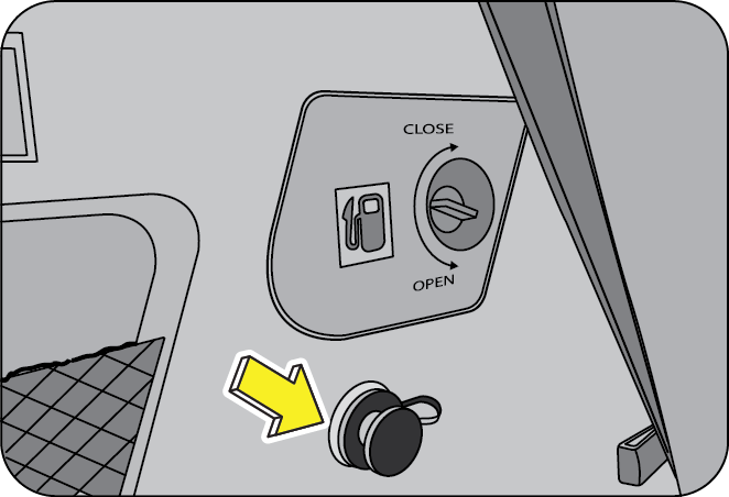
To avoid serious injury:
- Close the power outlet cap when not in use
- Do not allow children to use or play with the power outlet
- When using electrical appliances, strictly follow the manufacturers instruction manual
- Never use the power outlet for electric heaters while sleeping
- Never insert foreign objects into the power outlet
- Never use malfunctioning electrical appliances
- Never insert inappropriate or badly fitting plugs into the power outlet
Do not modify, disassemble or repair the power outlet in any way. Doing so may result in unexpected malfunction or fire, which could cause serious damage to equipment and/or personal injuries. Contact an Authorized Mahindra Dealer for any necessary repairs.
To prevent injuries and accidents, secure all electrical appliances before use. Do not use any appliance that may:
- Distract the driver while driving, or hamper safe driving
- Result in a fire or burn injuries due to the appliance rolling, falling or overheating
- Emit steam, while the windows of the passenger compartment are closed
- Use the power outlets only when the engine is running. Remove the plug from the power outlet after using the electric device. Using the power outlets when the engine is OFF or leaving the electric device plugged in for many hours may cause the battery to drain
- Do not use the power outlet to connect electric accessories or equipment that are not designed to operate on 12V
- Some electronic devices can cause electronic interference when plugged into the power outlet. These devices may cause excessive audio noise and may interfere with other electronic systems or devices in your vehicle
8.8 Instrument Panel Illumination
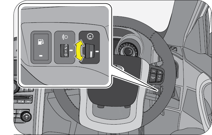
The instrument panel light intensity can be varied by the illumination control knob located on the RHS near the head lamp levelling switch.
Roll up/down for bright/dim intensity of illumination for the following lighting:
- Instrument cluster
- Ambient lamp
- Interior switches
- Infotainment screen/display
8.9 AUX and USB Ports
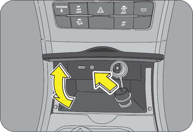
The AUX and USB ports are provided in the compartment below the centre switch bezel. They can be used as an input to the music system. You can connect i pods, USB memory sticks, etc., as an input and listen to the music through the vehicle speakers.
It is recommended to connect an input device only when the vehicle is stationary. Trying to connect an input device while driving may distract your attention and lead to accidents.
8.10 Exterior Lamps
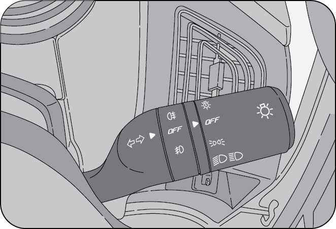
The lighting control stalk is located on the right hand side of the steering wheel and is a part of the combination switch. It controls operations of parking lamps, head lamps, head lamp beam selection, high beam flashing, front/rear fog lamps and turn signals when the ignition switch is ON.
8.10.2 Turn Signals
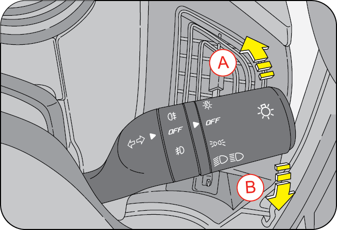
| A | Turn Signal - Left | B | Turn Signal - Rights |
8.10.3 Turn Signal - Right
- Push the lighting control stalk clockwise (to stop position B) to indicate a right turn. The instrument cluster arrow lamp pointing towards the right flashes along with the right side turn signal lamps (front, rear & ORVM) with chime indicating your intention of turning towards right
After you have completed your right turn, the stalk will automatically return to the neutral position switching OFF all the lamps.
8.10.4 Taking a Left turn
- Push the lighting control stalk anti-clockwise (to stop position A) to indicate a left turn. The instrument cluster arrow lamp pointing towards the left flashes along with the left side turn signal lamps (front, rear & ORVM) with chime indicating your intention of turning towards left
- After you have completed your left turn, the stalk will automatically return to the neutral position switching OFF all the lamps.
If the turn signal lamps on the instrument panel flash faster than normal, there may be a possibility that one or more of the turn signal lamp bulbs have blown. Replace the blown bulb immediately.
You can signal a lane change by moving the lighting control stalk clockwise or anti-clockwise to the limit point of free movement of the lever and releasing it once you change the lane.
Rotate the outer rotary switch on the lighting control stalk clockwise aligning the “arrow” on the stalk to “OFF” on the switch to switch OFF all lamps.
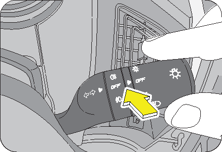
Rotate the outer rotary switch on the lighting control stalk clockwise aligning the “arrow” on the stalk to the “1st detente” position on the switch to switch ON the parking lamps.
The tail lamp, license plate lamp, instrument panel illumination lamps and all interior switches are also activated when the parking lamp is switched ON.
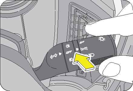
Rotate the outer rotary switch on the lighting control stalk clockwise aligning the “arrow” on the stalk to the “2nd detente” position on the switch to switch ON the head lamps.
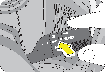
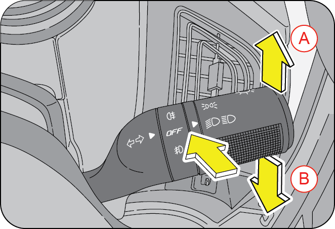
| A | Low Beam | B | High Beam |
Switch ON the head lamp, and push the lighting control stalk down (away) from steering wheel to switch ON the head lamp high beam or lift/pull the lighting control stalk up towards the steering wheel to switch ON the head lamp low beam. In head lamp high beam, the high beam telltale lamp in the instrument cluster illuminates indicating high beam option selected.
8.10.10 Head Lamp Flash
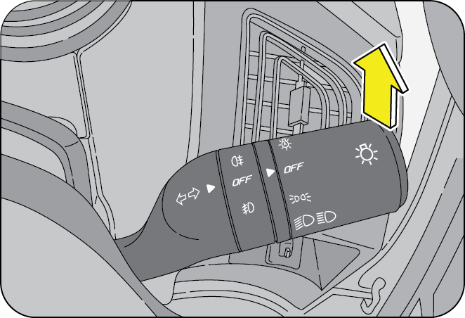
Pull the lighting control stalk (from the head lamp low beam position) towards the steering wheel to instantaneously flash the head lamp high beam. The head lamp flash works only when the head lamp is OFF or in low beam position.
The auto head lamp feature works on the outside ambient light intensity input by the RLS (Rain-Light Sensor). Based on this input, the head lamps are turned ON/OFF. For Eg., this feature will be helpful while driving through a tunnel or poor lit area.
The RLS is located behind the interior rear view mirror on the windshield.
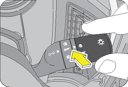
To turn ON the auto head lamp feature, rotate the outer rotary switch on the lighting control stalk anti-clockwise aligning the “arrow” on the stalk to the auto head lamp icon on the switch. This is indicated by the auto head lamp tell tale in the infotainment screen.
To de-activate the auto head lamp, rotate the outer rotary switch on the lighting control stalk clockwise aligning the “arrow” on the stalk to the OFF position on the switch.
There is a difference between ambient light intensity sensed by the RLS (Rain-Light Sensor) on the windshield and by the human eye. The RLS may activate the head lamps early during evening hours or may de-activate late during morning hours. This is absolutely a normal behavior.
In case of a windshield replacement, the RLS also needs to be replaced along with the windshield. An old RLS cannot be calibrated to a new windshield.
8.10.12 Head Lamp Levelling System
When the vehicle is either fully or partially loaded, it may have an upward inclination disturbing the head lamp aiming. A correct head lamp setting provides good visibility to the driver with minimum inconvenience to other road users.
To properly aim the head lamp beam, use the head lamp leveling switch. This switch is located on the right side of the steering column shroud in the instrument panel. This switch has four positions marked as 0, 1, 2 & 3.
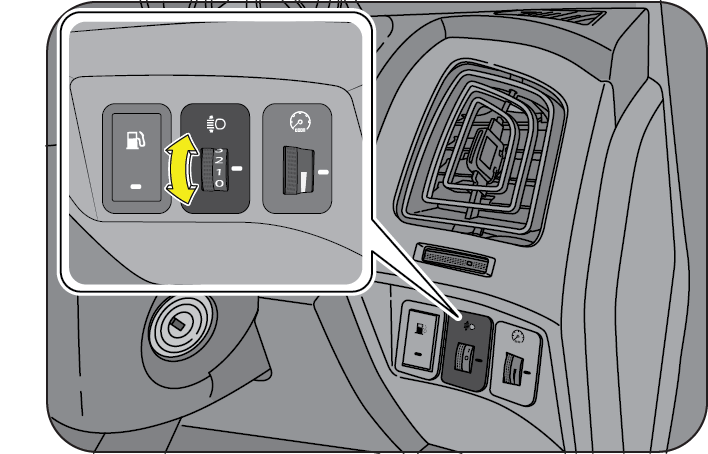
| Switch Position | Vehicle Loading Condition |
|---|---|
| 0 | Driver/Driver with Front Passenger |
| 1 | Driver + Front passenger + Second row occupied |
| 2 | All seats occupied |
| 3 | All seats occupied with luggage OR Driver with luggage at extreme rear side. |
Select the suitable switch position depending on the pay load as advised in the table.
The headlights can only be adjusted when the low beam is switched ON
8.10.13 Static Bending Lamp
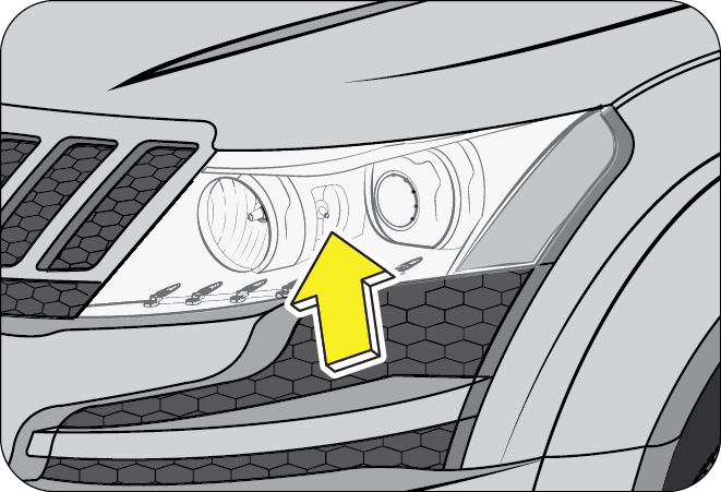
Static Bending lamps are available on both the head lamps. The static bending lamp assists the driver while taking a turn. It will be activated when the head lamp is ON and steering wheel turned more than 90° at 5 kmph or 45° at 100 kmph speeds.
8.10.14 Fog Lamps (if equipped)
Fog lamps are to be used along with head lamp low beam, to improve the vision during foggy and misty conditions.
8.10.15 Fog Lamps OFF

Align the “OFF” of inner rotary switch on the lighting control stalk to the “arrow” mark on the inner fixed stalk as shown to switch OFF the fog lamps.
8.10.16 Front Fog Lamps ON
To switch ON the front fog lamps, first switch ON the parking lamps, rotate the inner rotary switch on the lighting control stalk anti-clockwise aligning the front fog lamp icon to the “arrow” on the inner fixed stalk as shown. The rotary switch moves back to its neutral position once released.
The front fog lamp indicator in the instrument cluster indicates the operation status.
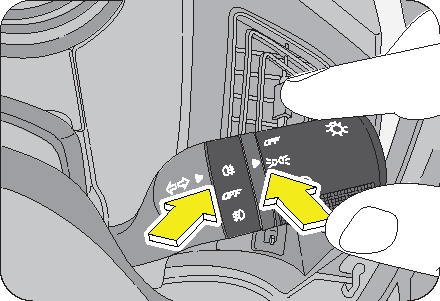
Fog lamps will turn ON only if parking lamp is ON.
8.10.17 Rear Fog Lamp
To switch ON the rear fog lamps, first switch ON the parking lamps, rotate the inner rotary switch on the lighting control stalk clockwise aligning the rear fog lamp icon to the “arrow” on the inner fixed stalk as shown. The rotary switch moves back to its neutral position once released.
The rear fog lamp indicator in the instrument cluster indicates the operation status.
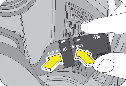
The rear fog lamps can be switched ON only along with the front fog lamps.
8.10.18 Puddle Lamp (if equipped)
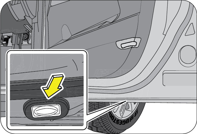
Puddle lamps are provided at the bottom of the front and rear doors. They are switched ON automatically when either of the front or rear doors are opened. This illuminates the ground below the respective door thereby assisting in a safe entry and exit.
8.10.19 Entry Assist Lamp (if equipped)
Entry assist lamps are located on the bottom of both left and right ORVM’s. They provide a illumination outside the driver and front passenger doors when the FMH or LMV features are activated.
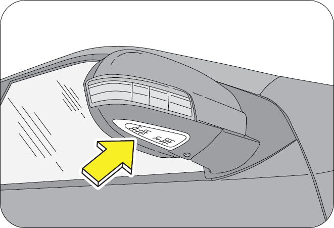
8.10.20 Follow-Me Home (FMH) (if equipped)
This feature helps the driver and passengers to easily get out of the vehicle during poor light conditions. The head lamp low beam and entry assist lamps are turned ON for about 20 seconds assisting the passengers to find their way.
To activate FMH:
- Switch OFF the parking lamps
- Remove the ignition key
- Open the driver door
- Head lamp and entry assist lamp switches ON for 20 seconds unless cancelled by UNLOCK signal.
For FMH to be activated, the vehicle should have been driven with the park lamps or auto head lamp ON before switching OFF.
To extend the FMH feature further for 20 seconds, press RKE LOCK button. This FMH extension can be availed for maximum 2 minutes from the first activation.
With FMH mode ON; First LOCK signal received from RKE will lock the doors and subsequent LOCK signal is used to toggle the head lamp ON and OFF.
With FMH mode ON, if UNLOCK signal is received twice from RKE; the feature gets deactivated and cannot be extended further. Also, the doors are unlocked and vehicle disarmed.
8.10.21 Lead Me to Vehicle (LMV) (if equipped)
LMV is the feature that switches the head lamp and entry assist lamps ON for 20 seconds helping the passengers to reach the parked vehicle safely and comfortably at night.
LMV is activated:
- Pressing the unlock button on the RKE under poor light conditions (if vehicle is equipped with auto head lamp)
- Pressing the unlock button on the RKE when FMH was activated while locking the vehicle previously (if vehicle is not equipped with auto head lamp)
- At the end of 20 seconds after activation
- When any door is opened
- Ignition is switched ON
- LOCK command is received from RKE
LMV is de-activated:
To extend the LMV feature further for 20 seconds, press RKE UNLOCK button. This LMV extension can be availed for maximum 2 minutes from the first activation.
With LMV mode ON; First UNLOCK signal received from RKE will unlock the doors and subsequent UNLOCK signal is used to toggle the head lamp ON and OFF.
8.10.22 Hazard Warning Lamp
The hazard warning lamp switch is located in the centre bezel switch bank on the instrument panel.
To turn the hazard warning lamp ON, push the switch in. All the turn signal lamps flash. The instrument cluster turn indicator lamps also flash indicating the same. To turn OFF, push the switch again.
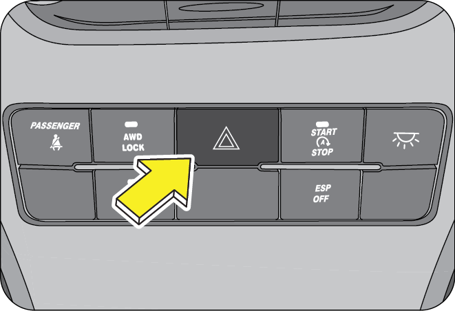
Use the hazard warning lamp when your vehicle is stationary or to warn other road users to be cautious while passing your vehicle.
The turn lamps do not work when the hazard warning lamps are operational.
8.11 Windshield Wipers
8.11.1 Wiper Control Stalk
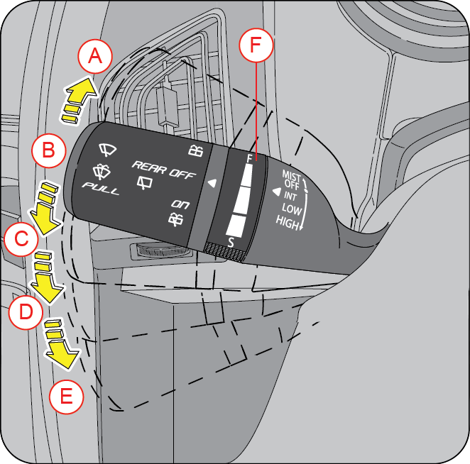
| A | Flick Wipe (MIST) | D | Low Speed (LO) |
| B | Off | E | High Speed (HI) |
| C | Intermittent (INT) | F | Intermittent Speed |
8.11.2 Wiper Off
The wipe function is OFF when the wiper control stalk is in neutral position (B).
8.11.3 Flick-Wipe (Mist)
Push the wipe control stalk to position (A) for a flick-wipe, hold to operate the wipe continuously (simultaneously lift the wiper stalk towards the steering wheel to operate the wash). The stalk automatically comes back to position (B) when released.
8.11.4 Intermittent (INT) Mode
Intermittent (INT) wiping is selected when the wipe control stalk is pushed down to position C. In the INT mode, the wiper operates on preset intervals.
The delay between each wipe can be varied by rotating the wiper speed intensity rotary switch (F).
8.11.5 Low Speed Wiping
Push the wipe control stalk down to the position (D) to operate the wiper at a fixed low speed.
8.11.6 High Speed Wiping
Push the wiper control stalk down to position (E) to operate the wiper at a fixed high speed.
The wipe/wash function can be activated only when the ignition is in “ON” position.
8.11.7 Auto Wipe
With the front wipers ON and rear wipers OFF, engaging the reverse gear activates the rear wiper.
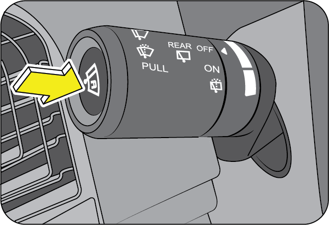
- The auto wipe feature works by sensing water (by the RLS) on the windshield. Based on this input, the wipers are turned ON/OFF. For Eg., this feature will be helpful when the rain is inconsistent.
- The RLS (Rain-Light Sensor) is located behind the interior rear view mirror on the windshield.
- To turn ON the auto wipe feature, press the outer rotary switch side/edge on the wiper control stalk. This is indicated by the auto wipe tell tale in the infotainment screen and the wiper performing one single wipe.
- The sensitivity of the RLS can be varied by the wiper speed intensity rotary switch (F) on the wiper stalk.
- To de-activate the auto wipe, switch OFF the ignition or press the auto wipe switch on the wiper stalk.
There is a difference between the RLS (Rain-Light Sensor) sensing rain (water) on the windshield and the human eye sensing rain. The RLS may activate the wipers when the windshield (top band) is wet. This is absolutely a normal behavior.
In case of a windshield replacement, the RLS also needs to be replaced along with the windshield. An old RLS cannot be calibrated to a new windshield.
8.11.8 Wipe/Wash
Pull/Lift the wiper control stalk towards the steering wheel from any position to activate wipe/wash function. Washer fluid from front washer reservoir is pumped and sprayed onto the windshield. The wipers wipe the windshield 3 times after the washer spray is stopped and wipe once after 5 sec. Hold the stalk in position for continuous spray of washer fluid.
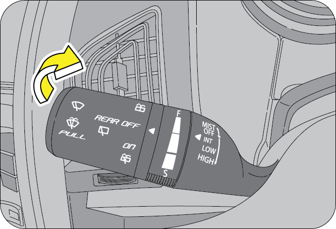
When wiper is in OFF or Interval mode:
After completion of the wipe/wash cycle, wipers return to their bottom position.
If the wipers are in interval mode and DWELL delay is less than or equal to 5 seconds, then the wiper will continue in the interval mode.
If the wipers are in interval mode, and DWELL delay is more than 5 seconds, then a further single wipe will be performed 5 seconds after the wash/wipe cycle. After the drip wipe (last wipe), wiper returns to normal interval wipe.
8.11.9 Rear Wiper
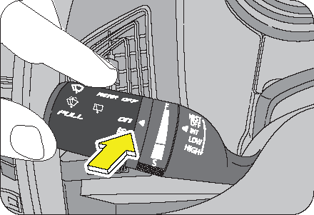
Rotate the outer rotary switch on the wiper control stalk to align the “arrow” on the stalk to the rear wipe “ON” position to operate the rear wiper.
8.11.10 Rear Wash
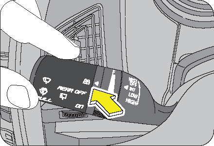
The rear windshield wash & wipe operates 3 to 4 times or as long as the stalk end is turned/rotated to the rear wash position. Wiping will continue for few seconds after releasing the stalk end switch.
If you switch OFF the ignition before switching OFF the wiper, the blades stop at random on the windshield. Switch ON the ignition and move wiper stalk to 'MIST' position to return the wipers to the park position, provided the wiper stalk is in OFF position.
Using a windshield washer in freezing temperatures could be dangerous. The washer fluid could freeze on the windshield, and block your vision resulting in an accident. If you operate your vehicle in temperatures below 4°C, use washer fluid with antifreeze protection.
- Do not operate the wipers when the windshield is dry. It may lead to scratches on the glass
- It is recommended not to use the wiper when the windshield glass is covered with debris, snow or leaves. Clean the glass before using the wiper to avoid damage to the wiper blades and glass
- Do not operate the windshield washer for more than 10 seconds or when the reservoir is empty.
With the front wipers ON and rear wipers OFF, engaging the reverse gear activates the rear wiper.
There are two nozzles with three adjustable washer jets in the front (below the wipers). Using a pin, the eye ball jets can be adjusted precisely for direction. Always direct the washer jet to hit middle of the windshield. This will enable the wiper blade to wipe the complete width of the windshield.
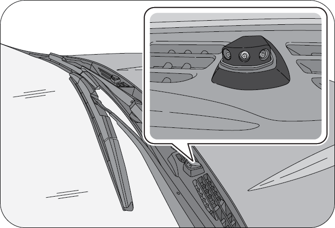
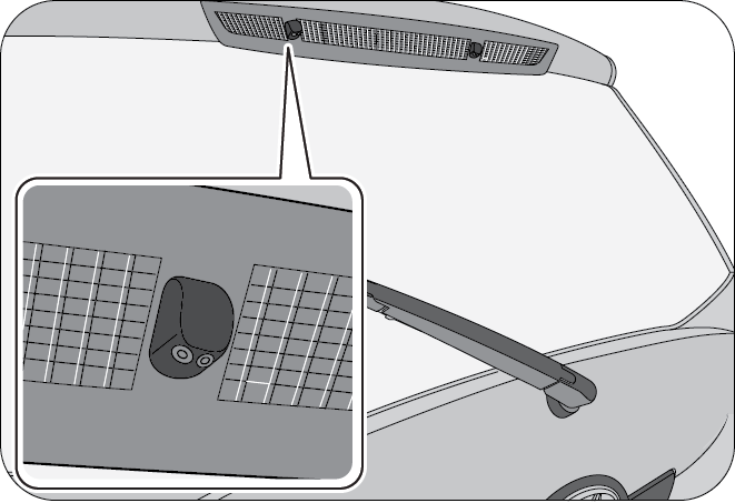
In the rear, two nozzles with twin adjustable washer jets are provided for the rear windshield wash. Adjust the nozzle to direct the washer jet to hit the middle of rear windshield using a pin. Rear windshield washer fluid is supplied from rear washer reservoir located in the back door.
8.12 Instrument Cluster
| A | Speedometer | E | Tachometer/RPM Gauge |
| B | Fuel Gauge | F | Temperature Gauge |
| C | Odometer/Trip meter/Gear Indicator | G | Reset Button |
| D | Warning/Telltale Lamps |
The instrument cluster comprises of the tachometer, speedometer, trip meter (A & B), Reset Button, Odometer, Fuel gauge, Coolant Temperature gauge, Warning lamps and Telltale indicators.
8.12.1 Tachometer
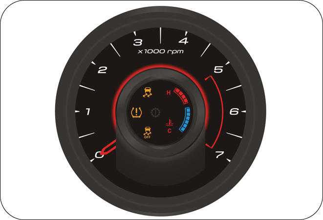
The tachometer indicates the real time engine speed in thousands of RPM (revolutions per minute). Each division is 500 RPM. Running the engine in very high RPM leads to excessive engine wear and poor fuel economy. Maintain steady engine speed below 2500 RPM and do not accelerate or decelerate abruptly.
Do not over-accelerate the engine during idling, this can cause severe engine damage and would be treated as abuse of the engine which is not covered by warranty.
8.12.2 Speedometer
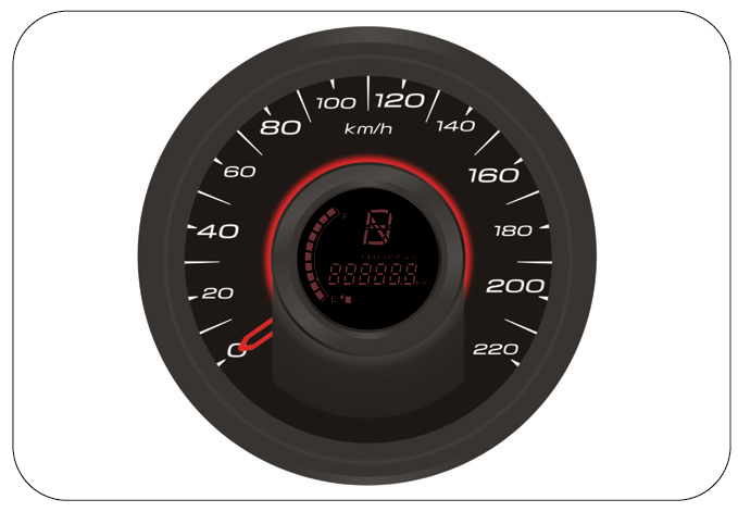
The speedometer indicates the real time road surface speed of the vehicle in kilometers per hour.
The vehicle speedometer is affected by size of the tires used. If the size of the tires are changed from those fitted at the factory, the speedometer might not display the correct road surface speed and distance travelled.
8.12.3 Odometer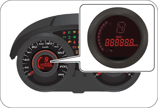
The odometer records and displays the total distance traveled in kms. Press the reset button (A) to cycle through odometer and tripmeter displays. Odometer cannot be reset.
8.12.4 Tripmeter and Reset Button
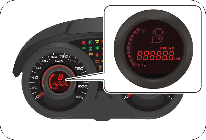
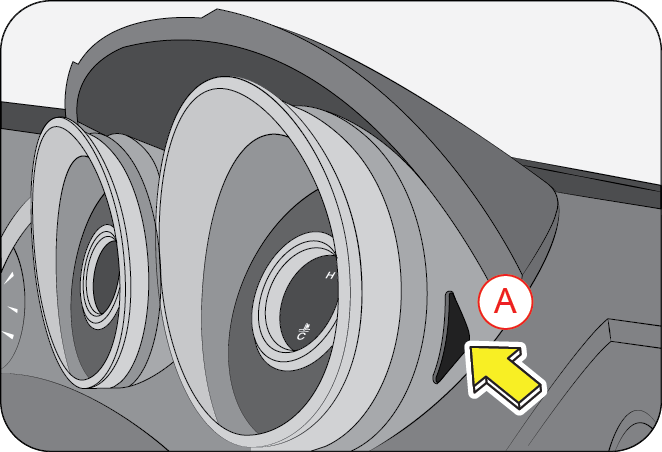
Tripmeter displays the elapsed distance travelled since the last trip reset. There are two tripmeter’s (A/B) which can be reset individually as necessary.
Odometer and Tripmeter are displayed only when the ignition is ON and their displays are cycled/toggled by the reset button (A).
- To select trip A or B, press and release reset button (A) for a second
- To shift from trip A to trip B or vice versa, press and release the reset button (A) again for a second
- While on trip A or B, press and hold the reset button (A) for more than 1 second to reset the respective trip reading to zero\
- Pressing the reset button (A) while in trip B, displays the odometer reading. Again pressing the rest button (A) displays trip A
The engine coolant temperature gauge functions only when the ignition is switched ON. It indicates the instantaneous engine coolant temperature. The coolant temperature varies with changes in weather, load on engine and driving pattern. Temperature rises from Cold (C) (Blue color) to Hot (H) (Red Color).
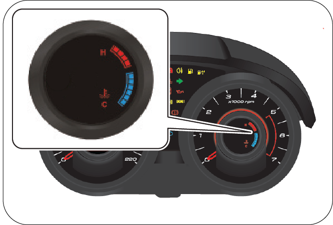
When coolant temperature reaches the red zone, the high engine coolant temperature warning lamp illuminates.
In such situations switch OFF the AC and observe for any improvements in temperature gauge. If not, stop the vehicle and allow the engine to cool down. Check the coolant level in the coolant reservoir and top-up if required. If the engine is still heating up, contact your nearest Authorized Mahindra Dealer.
Never remove the radiator cap when the engine is hot. The engine coolant is under pressure and could splash on to skin/eyes causing severe burns. Wait for the engine to cool down before adding coolant to the reservoir.
Do not continue driving the vehicle with a overheated engine. This will lead to damage of engine components and engine seizure.
8.12.6 Fuel Level Gauge
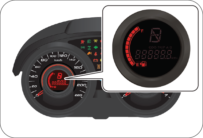
The fuel level gauge functions only when the ignition is switched ON. It gives the status of the fuel level in the fuel tank. F indicates the tank is full (70 liters), E indicates the tank in empty.
When the fuel level reaches the reserve, the last 2 bars are displayed. The last bar in the display blinks when the fuel in the tank reaches the low level (approx. 5 liters).
The amount of fuel required to fill the tank up may be less than the specified tank capacity, as a small amount of reserve fuel always remains in the tank.
On inclines or curves, due to the movement of fuel in the tank, the fuel level may fluctuate or the last bar may flash earlier than usual. Always check the fuel level when the vehicle is on level road.
If the last bar flashes even after filling sufficient fuel, contact your Authorized Mahindra Dealer as soon as possible.
When all the bars in the display starts blinking/ flashing, contact the nearest Authorized Mahindra Dealer at the earliest.
The direction of the arrow next to the fuel pump icon in the fuel gauge indicates the side on which the fuel lid is present.
8.13 Warning/Telltale Lamps in the Instrument Cluster

| A | Hill Descent Control (HDC) Lamp @ | O | Cruise Control Indicator@ |
| B | Seat Belt Warning Lamp | P | Low Engine Oil Pressure Warning Lamp** |
| C | Interactive Torque Management (ITM) Warning Lamp@ | Q | Hill Hold Control (HHC) Lamp@ |
| D | Parking Lamp | R | ESC System Warning Lamp@ |
| E | Left Turn Indicator | S | ESC OFF Lamp@ |
| F | Airbag Warning Lamp | T | Tyre Pressure Monitoring System Lamp (TPMS)** |
| G | Front Fog Lamp | U | Check Engine Lamp** |
| H | Glow Plug Indicator | V | Parking Brake ON/Brake Fluid Low Warning Lamp |
| I | Vehicle Armed Status Lamp | W | OBD Check Lamp* |
| J | Rear Fog Lamp | X | Head lamp High Beam Indicator |
| K | Low Fuel Warning Lamp | Y | Stop/Start Lamp |
| L | Water in Fuel Filter Warning Lamp* | Z | ABS Warning Lamp* |
| M | High Coolant Temperature Warning Lamp* | Z1 | Charging System Warning Lamp** |
| N | Right Turn Indicator | Z2 | Door Ajar Warning Lamp |
| @ if equipped | |||
| ** Come ON momentarily with ignition ON and will remain ON till engine is started. | |||
| * Come ON momentarily with ignition ON and go OFF in few seconds. | |||
8.13.1 Hill Descent Control (HDC) Lamp

The hill descent control lamp in the cluster illuminates when HDC is active/switched ON. If the HDC lamp in the cluster is continuously ON even after HDC being switched OFF, it indicates a malfunction in the HDC sys tem. Contact an author ized Mahindra dealer immediately.
8.13.2 Seat Belt Warning Lamp
The seat belt warning lamp illuminates reminding the driver to fasten the seat belt when the ignition is ON. The lamp will continue to illuminate till the driver fastens the seat belt properly.
8.13.3 Interactive Torque Management (ITM) Warning Lamp

The Interactive torque management warning lamp illuminates when there is a malfunction in the ITM system. Contact an authorized Mahindra dealer immediately.
8.13.4 Turn Lamps

The turn lamp arrows in the instrument cluster flash showing the direction indicated by the turn signals. A sudden increase in the rate of flashing indicates failure of one or more of the lamp bulbs. Have them replaced as soon as possible.
8.13.5 Airbag Warning Lamp
The airbag warning lamp in the instrument cluster illuminates when the ignition is switched ON and goes OFF in about 2 seconds once the engine is running. If the lamp remains ON continuously or flash’s intermittently, contact an authorized Mahindra dealer immediately.
Following conditions indicate airbag malfunction:
- Lamp fails to go OFF after engine is started
- Lamp does not illuminate at all
- Illuminates while driving
Contact an authorized Mahindra dealer immediately when the airbag warning lamp indicates a system malfunction. The airbag may not deploy when needed, which could result in serious or fatal injury, or it might deploy unexpectedly or unnecessarily, which may result in personal injury.
8.13.6 Front Fog Lamp (if equipped)

The front fog lamp telltale indicates the status of the front fog lamp. The front fog lamp can be switched ON only when the parking lamp is ON.
8.13.7 Low Fuel Warning Lamp

When the fuel level in the fuel tank falls below the reserve limit, the low fuel warning lamp is illuminated. Refuel sufficiently and the lamp goes out. If the lamp continues to remain ON even after refueling, contact an Authorized Mahindra Dealer.
8.13.8 Glow Plug Indicator

Glow plug indicator illuminates when the ignition is turned ON. It automatically goes OFF when the glow plug reaches the required temperature. Contact an Authorized Mahindra Dealer if the glow plug lamp does not illuminate with ignition ON or illuminates while driving.
8.13.9 Vehicle Armed Status Lamp
The vehicle armed status lamp flashes intermittently (few seconds frequency) once the ignition is switched OFF and the vehicle security system is armed (when locked using the RKE).
Fast blinking indicates a malfunction in the engine immobilizer system. Contact an Authorized Mahindra Dealer immediately.
8.13.10 Rear Fog Lamp (if equipped)

The rear fog lamp telltale indicates the status of the rear fog lamp. The rear fog lamp can be switched ON only when the front fog lamp is ON.
8.13.11 High Engine Coolant Temperature Warning Lamp
The high engine coolant temperature warning lamp flashes when the coolant temperature is above 105ºC. It starts to flash at double the rate when the temperature reaches 110ºC and will be continuously ON with buzzer alert when the temperature reaches 114ºC.
Do not continue driving the vehicle with an overheated engine. This may result in engine damage, which will not be covered by the limited warranty.
8.13.12 Water-in-Fuel Warning Lamp
The water-in-fuel warning lamp illuminates when the accumulation of water in the fuel filter reaches the maximum permissible limit. The fuel filter needs to be drained. Contact an authorised Mahindra dealer.
Do not continue driving the vehicle with the water in fuel warning lamp ON. This may result in fuel pump/ other fuel system component damage, which will not be covered by the limited warranty.
8.13.13 Cruise Indicator

The cruise control lamp illuminates when the ignition is switched ON and goes off in about 2 seconds indicating normal status. The lamp blinks if the accelerator is depressed, while in cruise mode
When SET+ button in the steering wheel is pressed, cruise control is activated and the lamp illuminates indicating the vehicle is in cruise mode.
When CRUISE OFF button in the steering wheel is pressed, the cruise mode is deactivated and the lamp goes OFF indicating that the vehicle is not in cruise mode.
If the lamp does not illuminate when the vehicle is in cruise mode or does not go OFF when the vehicle is out of cruise mode, there is a possible malfunction in the lamp or the cruise control system. Have the vehicle checked by an authorized Mahindra dealer.
8.13.14 Low Engine Oil Pressure Warning Lamp
The low engine oil pressure warning lamp illuminates when the ignition switch is turned ON goes out as soon as the engine is started. If the lamp remains ON even after starting the engine, or illuminates while driving, stop immediately, check the oil level after 2-3 minutes. If low, add engine oil to the “MAX” level and check status. If problem persists, contact an Authorized Mahindra Dealer immediately.
Operating the vehicle with the low oil pressure warning lamp ON could cause sudden unexpected engine failure and loss of vehicle control, resulting in an accident and/or serious personal injury.
Do not run the engine with low oil pressure warning indicator ON. This may result in engine damage, which will not be covered by the limited warranty.
8.13.15 Hill Hold Control (HHC)

The hill hold control lamp illuminates when there is a malfunction in the HHC system. Contact an authorized Mahindra dealer immediately.
8.13.16 ESP System Warning Lamp
While driving, if the ESC system warning lamp blinks, it indicates that ESP has taken control of the vehicle stability. If the lamp remains ON, it indicates the malfunction in the ESP System. Contact the nearest Authorized Mahindra Dealer.
8.13.17 ESP OFF Lamp
The ESP OFF lamp illuminates when the ESP has been switched OFF manually.
8.13.18 Tyre Pressure Monitoring System Lamp (TPMS)

The TPMS lamp illuminates if there is a tyre pressure or temperature difference in one of the tires. The TPMS lamp blinks (for approx. 75 sec.) and then illuminates continuously when there is a malfunction in the TPMS.
8.13.19 Check Engine Lamp
The check engine lamp illuminates when the ignition is switched ON and goes out in 2 seconds indicating normal status. The lamp blinks or illuminates continuously if there is a fault in the engine management system. Switch OFF the engine immediately. Contact the nearest Mahindra dealer for necessary repairs.
8.13.20 Parking Brake Lamp

The lamp illuminates when; Parking brake is engaged or when brake fluid level is low or when front brake pads are worn. If the lamp illuminates while driving, do the following:
- Check if the parking brake is engaged. If yes, disengage it
- Check if brake fluid level is low. If yes, top-up brake fluid to the required level
- If the brake lamp still continues to illuminate, immediately get the vehicle checked at an Authorized Mahindra Dealer.
Clean the top of the brake fluid reservoir before removing the cap. Make sure no dirt, impurities or other items fall into the reservoir. Do not leave the cap off for more than a few minutes. Any contaminants, impurities or moisture in the brake fluid can affect brake operation, resulting in an accident.
If the brake warning lamp comes ON while driving, the brake system might not be working properly. The pedal might be harder to operate or might go closer to the floor and it can take longer to stop. Pull off the road carefully and stop the vehicle. Have the vehicle towed to the nearest Authorized Mahindra Dealer for checks or repairs.
Driving the vehicle with the brake warning lamp ON or when you suspect brake trouble is very dangerous and could result in serious injuries. Have your vehicle towed to an Authorized Mahindra Dealer.
8.13.21 OBD Check Lamp
The OBD check lamp illuminates when the ignition is switched ON and remains ON till the engine is started indicating normal status. If the lamp remains ON, it indicates a potential malfunction.
There may be a malfunction in:
- The fuel management system
- The emission control system
- Systems which affect emissions
Such malfunctions may result in excessive emissions. Contact an Authorized Mahindra Dealer immediately.
8.13.22 Head Lamp High Beam Lamp

The head lamp high beam telltale illuminates whenever the head lamps are switched ON to high beam or when the head lamp flash is used.
8.13.23 Stop/Start Lamp

Graphic The Stop/Start - Stop/Start lamp flashes when the vehicle/engine is about to stop through the Stop/ Start System. The lamp illuminates continuously when the vehicle/engine has been switched OFF by the Stop/Start System. On restarting the vehicle/ engine again by using the clutch/key, the lamp goes out.
8.13.24 Anti-lock Brake System (ABS) Malfunction Lamp (if equipped)

The ABS malfunction lamp illuminates when the ignition is switched ON and goes OFF after about 2 seconds. If the ABS malfunction lamp continues to remain ON or illuminates while driving (and the brake system warning lamp is OFF), ABS will not operate. But the brake system will still operate conventionally. In this condition, the wheels can lock during severe braking. Have the vehicle checked by an authorized Mahindra dealer as soon as possible.
However, if ABS malfunction lamp and brake warning lamp are simultaneously glowing, there is a severe malfunction in the ABS. Operate the vehicle with extreme care and have the vehicle checked as soon as possible at an authorized Mahindra dealer.
8.13.25 Battery Charging System Warning Lamp

The battery charging system warning lamp illuminates when the battery is not being charged or when there is a malfunction in the alternator.
This lamp illuminates when the ignition is switched ON and goes out as soon as the engine is started. If the lamp continues to remain ON even after starting the engine, it is an indication that the battery is not being charged or there is a malfunction in the alternator. Check the alternator drive belt for looseness/breakage. If the drive belt is okay, switch OFF all unnecessary electrical equipment and recheck. Contact an Authorized Mahindra Dealer for further assistance.
8.13.26 Door Ajar Warning Lamp
The door ajar warning lamp illuminates and the buzzer chimes 3 times when any of the doors including the hood and back door are open during ignition ON. The lamp goes OFF when all the doors are closed properly.
8.14 Radio Frequency ID (RFID) Tag
Your vehicle is fitted with a RFID tag as per CMVR regulations. It is located on the top LH corner of front windshield.
RFID tag is used for Electronic Toll Collection (ETC).
Do not peel or remove the RFID.
9 STEERING AND BRAKES
9.1 Steering
Your vehicle is equipped with power steering. Power steering uses energy from the engine to decrease the driver's effort in steering the vehicle. The power steering system will give you good vehicle response and increased ease of maneuverability in tight spaces. If for some reason the power assist is interrupted, it will provide mechanical steering capability to steer the vehicle. Under these conditions, you will observe a substantial increase in steering effort, especially at very low vehicle speeds and during parking maneuvers.
Upon initial start-up in cold weather, the power steering pump may produce noise for a short amount of time. This is due to the cold, thick fluid in the steering system. This noise should be considered normal, and it does not in any way damage the steering system.
Continued operation with reduced power steering performance could pose a safety risk to yourself and others. Have the vehicle serviced at specified intervals or whenever a power steering problem is noticed.
Do not grip the steering wheel spokes when driving off road. A bad bump could jerk the wheel and injure your hands. Keep both hands especially your thumbs on the outside of the steering wheel rim.
- Never hold the steering wheel to the extreme right or the extreme left for more than a few seconds when the engine is running
- Heavy or uneven steering efforts may be caused by low power steering pump fluid level. Check for low power steering pump fluid level before seeking service by an Authorized Mahindra Dealer
- Do not fill the power steering pump reservoir above the MAX mark on the reservoir, this may result in leaks from the reservoir
If the power steering system breaks down (or if the engine is turned OFF), you can still steer the vehicle manually, but it takes more effort.
- Under inflated tire(s) on any wheel(s)
- Uneven vehicle loading
- High crown in the centre of the road
- High crosswinds
- Wheels out of alignment
- Wheels out of balance
- Loose or worn suspension components
9.1.1 Tilt Steering
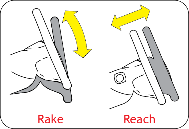
The steering wheel can be adjusted for both rake and reach as required using the lever in the steering shroud under the steering wheel.
To tilt/adjust the steering wheel;
- Pull the tilt lever down to unlock.
- Raise or lower the steering wheel to the desired position.
- Pull or push the steering wheel to the desired position.
- Push the tilt lever back up to its original position to lock the steering.
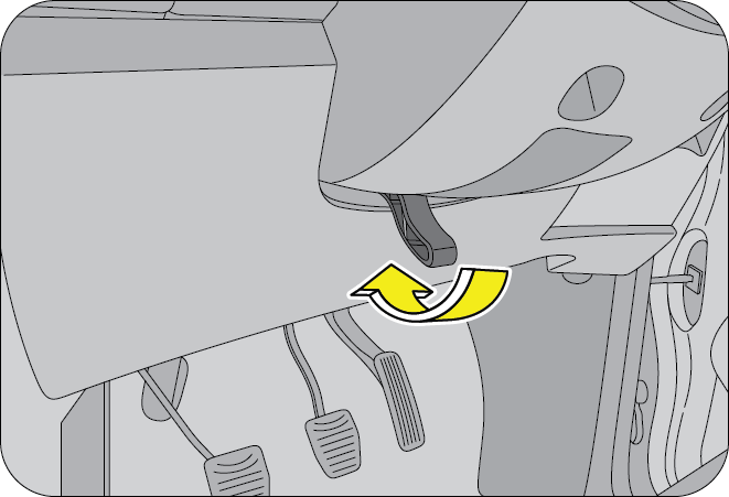
improperly locked steering wheel could cause loss of control and lead to accidents. Never adjust the steering wheel while driving.
9.2 Steering Controls - Audio
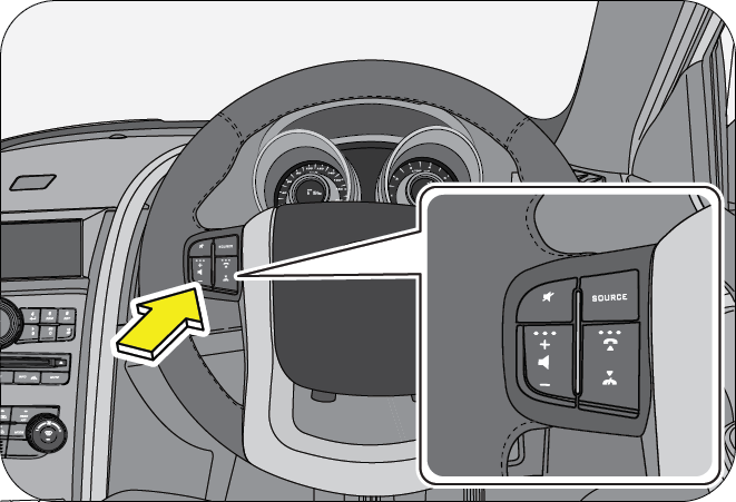
The steering wheel also houses switches to control the main audio functions.
Refer to the Audio/Infotainment Manual for complete information on audio system features and controls.
9.2.1 Steering Audio Operations
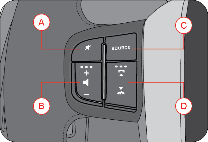
| A | Mute | C | Source Selection |
| B | Volume + / - | D | Up / Down or Call Selection |
- TO TURN AUDIO ON/OFF - Press the mute button for 2 seconds
- SOURCE - Press SOURCE button to toggle between AUX, CD, TUNER & USB mode
- VOLUME CONTROL - Press ‘+’ and ‘-’ button to increase or decrease the volume.
- MUTE - Press MUTE button to mute audio while in TUNER and AUX mode and pause the song while in CD, USB mode
- CD USB MODE - Press ‘UP’ /‘DOWN’ button to go to next/previous track
TUNER MODE - Press ‘UP’ /‘DOWN’ button to go to next/ previous frequency. Press ‘UP’ /‘DOWN’ button for 2 seconds to AUTO TUNE
9.3 Brakes
Your vehicle is equipped with disc brakes in the front and rear.
Disc brakes offer good braking capability and reduced stopping distance. Wet brake discs result in reduced braking efficiency. After a car wash or driving the vehicle through water, dab the brake pedal while driving to remove the film of water from the brake pads. Brake pads feature wear indicator. When the brake pad is worn, metallic squeal noise is heard indicating the pad wear. Have them replaced immediately.
Driving with wet brakes is dangerous. Stopping distance increases considerably when braking.
Dry the brakes by driving at very slow speed and applying the brakes lightly until the brake performance become normal.
Even if the power assist (hydraulic assistance) is completely lost, the brakes will still work. The brake pedal would be much harder than normal and the vehicle stopping / braking distance will be longer than usual.
9.3.1 Parking on a Hill/Incline
If you have to park facing uphill, select first gear and turn the front wheels away from the kerb. If you have to park facing downhill, select reverse gear and turn the front wheels towards the kerb. Always ensure the vehicle is in gear and parking brakes is engaged before leaving the vehicle.
9.3.2 Parking Brake
To apply the parking brake, pull the park brake lever up as firmly as possible. When the parking brake is applied with the ignition ON, the brake warning lamp in the instrument cluster illuminates. To release the parking brake, pull the parking brake lever up slightly, press the release button on the lever tip and lower the parking brake lever completely.
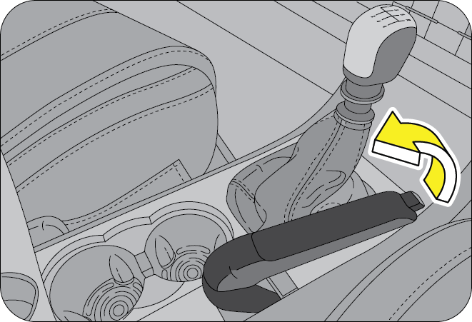
The brake warning lamp indicates only the parking brake status. It does not indicate the degree of brake application. Be sure the parking brake is firmly set when parked and the gear lever is in gear. When parking on a hill you should apply the parking brake before placing the shift lever gear, since the load on the transmission locking mechanism may make it difficult to move the shift lever out of gear.
- The parking brake should be adjusted as per recommended maintenance schedule
- Always apply the parking brake when leaving the vehicle, and be certain to leave the transmission in gear. Failure to do so may allow the vehicle to roll and cause damage, hit a bystander resulting in serious personal injury
- Leaving unattended children in a vehicle is dangerous for a number of reasons. Children should be warned not to touch the parking brake or the gear lever. Do not leave the key in the ignition. A child could move the vehicle leading to accidents
Engaging the parking brake while the vehicle is in motion can cause the rear wheels to lock up. You could lose control of the vehicle and cause an accident.
Although the parking brake is not recommended to stop a moving vehicle, if the normal brakes fail, the parking brake can be used to stop your vehicle in an emergency. However the vehicle's stopping distance increases greatly affecting the handling of the vehicle adversely.
The parking brake should always be applied when the driver is not in the vehicle.
9.4 Anti-Lock Brake System (ABS) (if equipped)
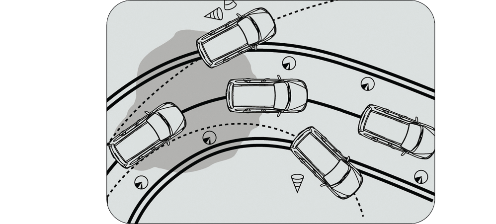
The Anti-lock Brake System (also called as ABS) is designed to help prevent lock-up of the wheels and stable stopping of vehicle during a sudden, panic emergency braking or braking on slippery road surfaces. The ABS system takes input from wheel speed sensors and brake pedal switch to control the brake fluid pressures at the wheels to avoid wheel lock-up. It allows vehicle to be steered during braking.
The minimum speed for ABS to function is 12 kmph. ABS is activated only during wheel lock conditions where ABS takes over and prevents wheel lock.
During the ABS operation, a slight pulsation may be felt in the brake pedal to indicate ABS is active. You may also hear motor noise from the engine compartment. It is recommended to hold the brake pedal firmly while the ABS is active rather than pumping the brake pedal.
Depressing the brake pedal on slippery road surfaces as on a manhole cover, a steel plate at a construction site, a joint in a bridge, etc. on a rainy day, tends to activate the anti-lock brake system.
The Anti-lock brake system is not designed to shorten the stopping distance: Always drive at a moderate speed and maintain a safe distance from the vehicle in front of you. The stopping distance may be longer in the following cases:
- Driving on rough, gravel or snow covered roads.
- Driving with tyre chains installed.
- Driving over the steps such as the joints on the road.
- Driving on roads where the road surface is pitted or differences in surface height.
Do not overestimate the Anti-lock Brake System: Although the Anti-lock Brake System assists in providing vehicle control, it is still important to drive with all due care and maintain a moderate speed and safe distance from the vehicle in front of you. There are limits to the vehicle stability and effectiveness of steering wheel operation even with ABS active.
If tyre grip performance exceeds its capability, or if hydroplaning occurs during high speed driving in the rain, the Anti-lock Brake System will not assist with vehicle control.
9.5 Electronic Brake Force Distribution (EBD) (if equipped)
EBD, as a subsystem of the ABS system, controls the effective adhesion utilization of the rear wheels. EBD aids in distributing the brake forces more evenly leading to better vehicle stability during braking.
Typically, the front end carries more weight and EBD distributes less braking pressure to the rear brakes avoiding a lock up/skid.
For example, under light loads EBD applies less effort to the rear brakes and for heavy loads it allows full braking effort to the rear wheels.

9.6 Hydraulic Brake Assist (HBA) (if equipped)
ESP system recognizes / identifies an emergency braking situation from the braking characteristics and thereby achieves a braking output equivalent to a full force demand at the controls. HBA automatically boosts the braking force to the maximum and helps to stop the vehicle as quickly as possible.
Pressure should be maintained on the brake pedal during entire brake application. If the brake pedal is released, HBA will stop operating
10 HEATING, VENTILATION AND AIR-CONDITIONING SYSTEM (HVAC)
HVAC system provided in the vehicle enables occupants to automatically/manually adjust air flow distribution pattern, air flow rate, air intake mode and air temperature inside passenger compartment. By appropriately adjusting the control knobs/switches provided on the HVAC control panel, located on centre console, occupant’s comfort can be ensured. HVAC system also helps in defrosting and defogging/ de-misting the windshield and windows.
Air flow direction can be further controlled by adjusting louvers of air vents. An air filter is provided at the inlet of HVAC blower.
Engine coolant is utilized to heat the cabin air. For cooling the cabin air, an air conditioning circuit based on the vapor compression refrigeration cycle is used. The air conditioning system uses a refrigerant along with a suitable lubricating oil. Although being non-ozone depleting, the refrigerant is a greenhouse gas, hence once allowed to escape in the atmosphere, it adversely affects the environment by contributing to global warming/climate change.
Refrigerant used in system is a hazardous liquefied gas and is under high pressure. The refrigerant is colorless and has ethereal or faint sweetish odor. Exposure of refrigerant to skin or eyes may cause irritation and frostbite. They can also cause suffocation, dizziness and loss of concentration. When mixed with compressed air or certain other refrigerants, it may form flammable mixture. Never try to service HVAC system yourself which would involve refrigerant handling.
Multiple vents are provided for distributing the air, being force-circulated by HVAC blower, throughout the passenger compartment.
To ensure sufficient air flow and hence adequate HVAC system performance, air flow path should be kept free of obstructions. Keep system’s air intake, located near plenum appliqué, free of snow, leaves and other debris. Also keep the area in front of air vents free of any obstruction inside the cabin.
10.1 HVAC Overview
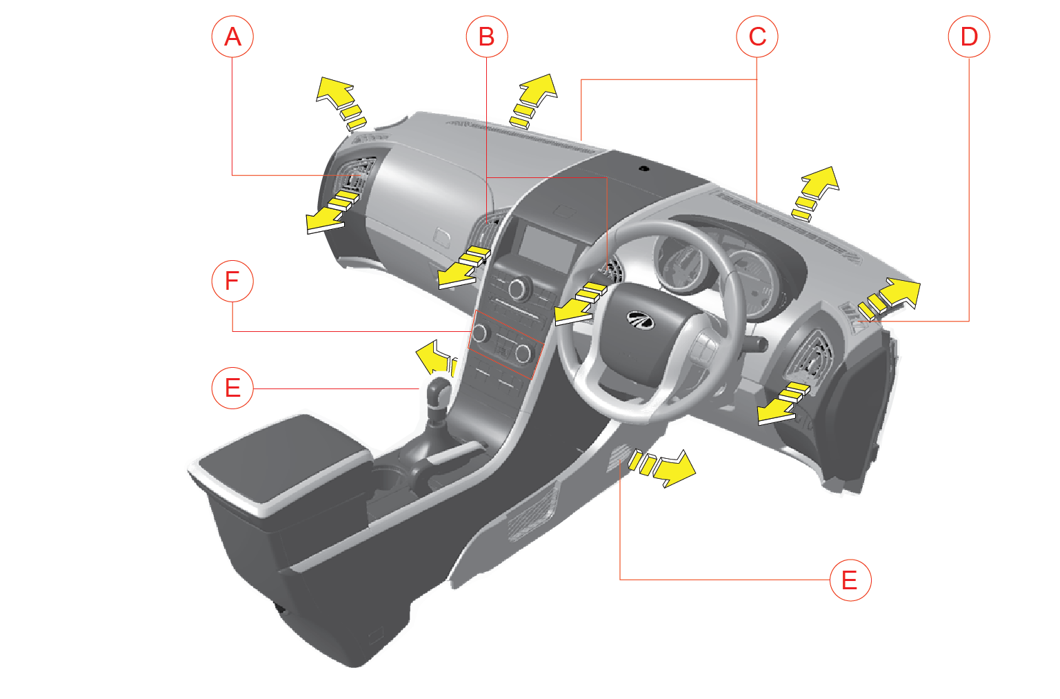
| A | Side Vents | D | Side Defrost Vents |
| B | Centre Vents | E | Foot Vents |
| C | Windshield Defrost Vents | F | HVAC Controls |
10.1.1 Centre/Side Vents
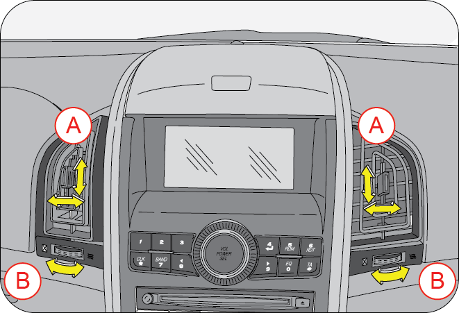
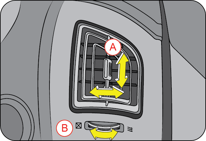
| A | Adjustable Louvers | B | Thumb Wheel |
Two centre vents are located on either side of the infotainment screen in the centre console. The two side vents are located one each at the left and right extreme ends of the instrument panel. Both the centre and side vents provide air flow to the front seat passengers.
Rotate the thumb wheel (B) left to close or right to open the air vent. Direct air to the desired direction by the adjusting louvers (A) up/down or left/right.
10.1.2 Defrost Vents - Side/Windshield
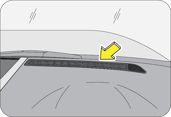
There are four defrost vents in your vehicle; two side defrost and two windshield defrost vents. They are located just below the windshield. The side defrost vents prevent the front windows from de-misting, whereas the windshield A Adjustable Louvers B Thumb Wheel defrost vents help in clearing the mist from windshield.
10.1.3 Second/Third Row Roof Vents
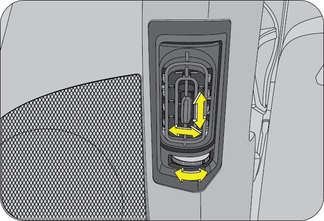
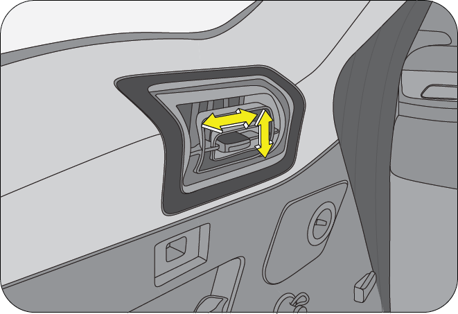
Two (LH & RH) vents for the second row are provided on the B-Pillars. The vents have adjustable louvers to direct the air flow and thumb wheels for vents open/close operations.
The third row vents (LH & RH) are located on side trims on either side of the third row seats.
10.2 Climate Control
There are two types of climate control depending on the variant ;
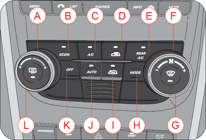
| A | Temperature Control Dial | G | Front Windshield Defrost |
| B | Economy Button (ECon) | H | Air Distribution Mode |
| C | AC ON | I | Fresh Air Mode |
| D | Re-circulation Mode | J | Auto Mode |
| E | Rear AC (Third Row) | K | Blower Fan OFF |
| F | Blower Fan Speed Control Dial | L | Rear Windshield Defrost |
Manual Climate Control
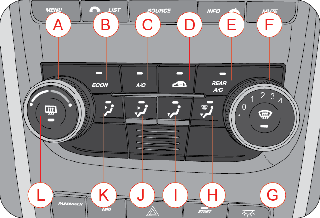
| A | Temperature Control Dial | G | Front Windshield Defrost |
| B | Economy Button (ECon) | H | Floor Defrost Mode |
| C | AC ON | I | Floor Mode |
| D | Re-circulation Mode | J | Face Floor Mode |
| E | Rear AC (Third Row) | K | Face Mode |
| F | Blower Fan Speed Control Dial | L | Rear Windshield Defrost |
10.3 Temperature Control
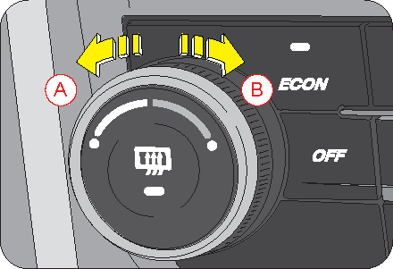
| A | Cool Air |
| B | Hot Air |
By operating the temperature control knob, temperature of air being discharged from various vents can be adjusted to the desired level. Engine coolant is utilized to heat whereas the air conditioner is used to cool the air inside the AC unit. Based upon selected position of the temperature control dial, the desired discharged air temperature can be obtained.
By rotating the dial counter-clockwise and setting it to the extreme left position, cool air is discharged.
When the dial is rotated clockwise, the discharge air progressively starts getting warmer.
By rotating the dial further in the clockwise direction and setting it to the extreme right position, hot air is discharged.
10.4 Blower Speed Control
The controls differ depending on the variant (Automatic or Manual Climate Control).
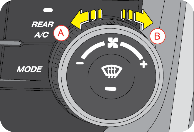
Blower force-circulates air through the HVAC unit and distributes it throughout the passenger compartment.
To increase the blower speed, rotate the control dial clockwise (B) and to reduce the blower speed, rotate the dial counter clockwise (A).
The same is also indicated in the infotainment screen (in Automatic Climate Control equipped vehicles).
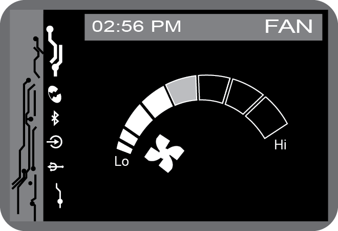
The blower speed control dial is also used to switch ON the blower alone when needed. Use the OFF button on the switch bank to switch OFF the blower.
This blower speed control does not control the air flow to third row vents.
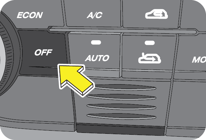
The blower OFF button turns the blower OFF. This in turn switches OFF the AC also.
The blower alone can be switched ON by rotating the blower control dial.
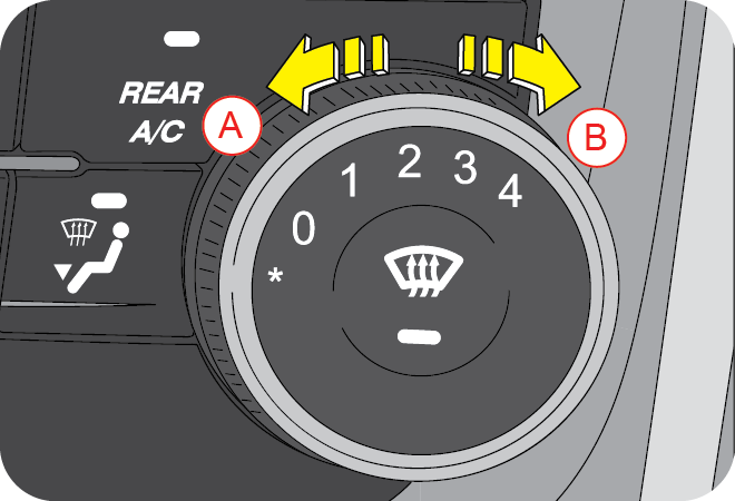
Blower force-circulates air through the HVAC unit and distributes it throughout the passenger compartment.
To increase the blower speed, rotate the control dial clockwise (B) and to reduce the blower speed, rotate the dial counter clockwise (A).
To switch OFF the blower, rotate the dial to “0”.
A blower control is provided below the third row (RH) vent to control the air flow to the third row vents.
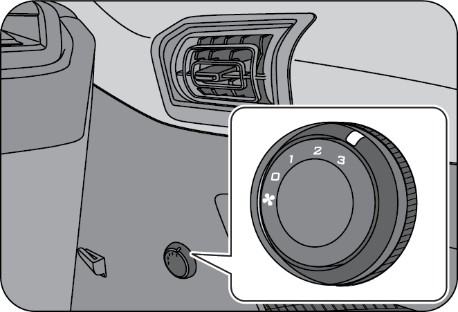
The third row AC is switched ON by the Rear AC button on the central switch bank. The airflow is controlled by the blower control on the third row RH side trim.
10.5 Economy Button (ECon)
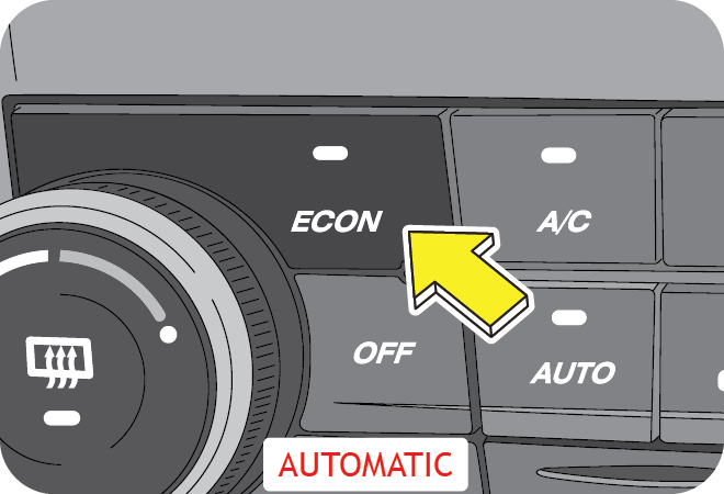
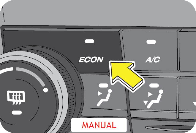
ECON switch turns ON economy mode. During ECON AC operation the system automatically cuts OFF at a higher temperature than normal AC. The operation can be used during mild weather conditions for better fuel efficiency. Comfort level may be compromised during this operation.
LED on the button indicates the status of the button. Press the ECON switch again to turn OFF economy mode.
10.6 Air-conditioner ON (AC ON)
This button turns the air-conditioner ON or OFF. Adjust the temperature control dial as per the temperature requirement. LED on the button indicates the status. Push the button to turn ON/OFF the AC.
When the air conditioner is functioning, air gets cooled and de-humidified before being circulated inside the cabin. In hot weather conditions, it will take a slightly longer time to cool the interior as compared to cooler weather. Fuel consumption will be relatively higher if the vehicle is being driven with the air conditioner ON.
AC will function only when both engine and blower are switched ON.
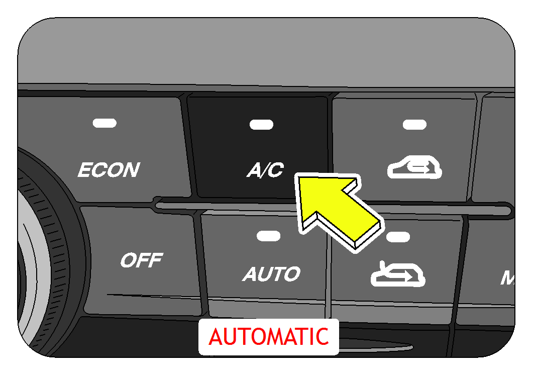
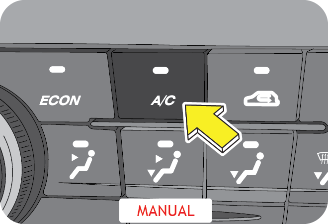
- In certain operating conditions when the engine gets overheated, the engine management system may switch off the air conditioner intermittently.
- The air conditioner should be operated at least for ten minutes once every fortnight, even during winter months. This allows AC system components to get lubricated periodically and ensures optimum system
- During extreme cold weather conditions, the air conditioner may not function until temperature of the air near the evaporator rises above a predefined threshold.
- When air conditioner is ON, moisture is extracted from the air. The resulting condensate is drained off from the vehicle. It is therefore normal, if you see a small pool of water under your vehicle.
10.7 Re-circulation Mode
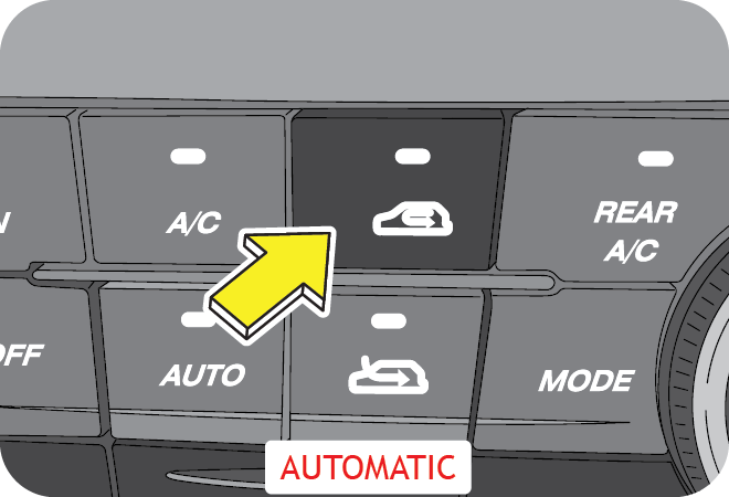
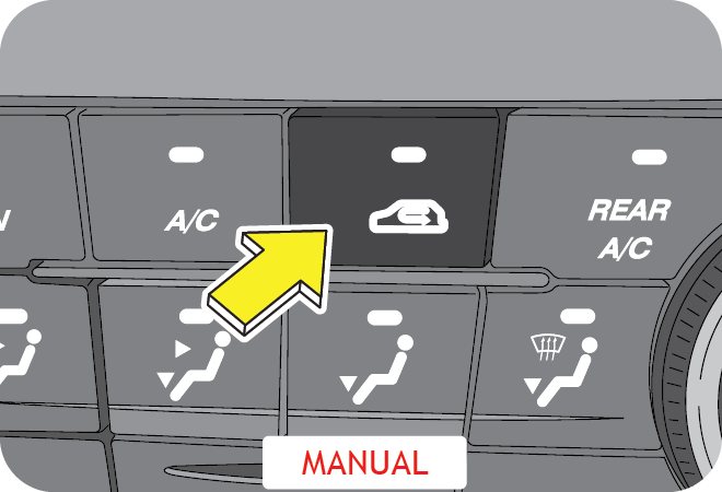
To set the HVAC system to recirculation mode, press the recirculation mode button. The LED on the button illuminates, indicating the recirculation mode is active.
In this intake mode, the air from inside the passenger compartment will be sucked by the blower and utilized further to ventilate/cool/heat the cabin.
For quick cabin cooling/heating or while driving through dusty/polluted region, re-circulation mode can be selected for short periods. Driving with this mode active may lead to better fuel economy and longer HVAC filter life.
However, running the air conditioner in re-circulation mode for long will make cabin air too dry and oxygen level drops inside cabin turning the air stale. On the contrary, keeping air intake control in recirculation mode for long, with air conditioner switched OFF, will make cabin air too humid and are more likely to become foggy. Hence never drive in recirculation mode for long, shift back to fresh air mode as soon as possible.
Never keep recirculation mode selected continuously for long. Prolonged use of the HVAC system in recirculation mode may cause windshield/windows to mist/fog-up, impairing visibility which can lead to an accident, endangering you and others.
10.8 Fresh Air Mode
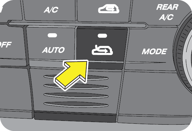
To set the HVAC system to fresh air mode, press the fresh air mode button. The LED on this button illuminates, indicating that fresh air mode is active.
In this intake mode, fresh air from outside the vehicle is sucked by the blower and utilized further to ventilate/cool/ heat the cabin.
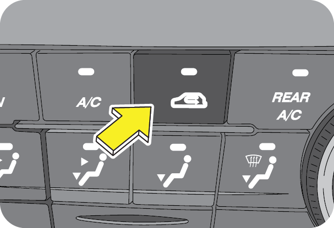
To set the HVAC system to fresh air mode, press the re-circulation mode button again. The LED on this button switches OFF, indicating that re-circulation mode is active.
10.9 Rear AC
The rear AC provides cooling for the third row AC vents. Adjust the temperature control dial as per the temperature requirement. LED on the button indicates the status.
The rear AC can be switched ON only when the AC button (front/second row AC) is ON.
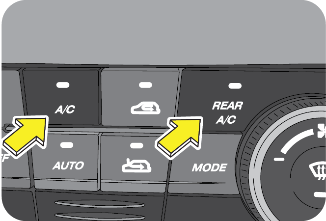
10.10 Auto Mode (Automatic Climate Control only)
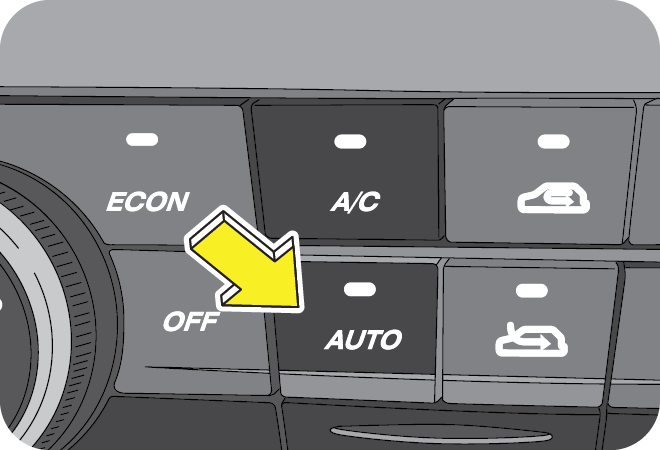
The auto mode can be used to control the complete air conditioning operation of the vehicle automatically. The auto mode controls blower fan speeds, air intake mode, temperature and modes (vents) based on the set temperature.
All the air conditioning operations can also be controlled manually as explained in the previous sections.
10.11 Air Distribution Mode
Air distribution mode button allows you to select the below air flow patterns;
- Face Mode
- Face and Floor Mode
- Floor Mode
- Floor Defrost Mode
- Defrost Mode
Depending on the variant, the operation of air distribution mode changes.
Each press of mode switch changes the flow pattern accordingly.
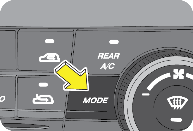
The air distribution inside the vehicle can be chosen by the Mode button.
Press the required mode button on the switch bank.
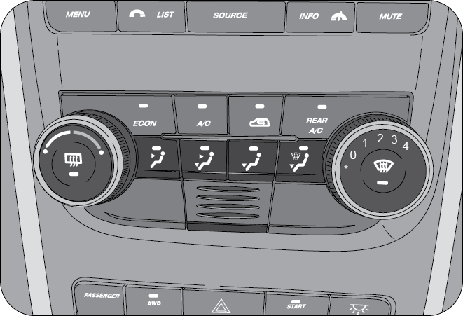

Air is discharged through the centre and side vents on the instrument panel, and through the second row B-pillar vents.
Corresponding information is displayed on the infotainment screen.
10.11.2 Air Distribution - Face & Floor Mode
Air is discharged through the centre, side and foot vents on the instrument panel, and through the second row B-pillar vents.
Corresponding information is displayed on the infotainment screen.
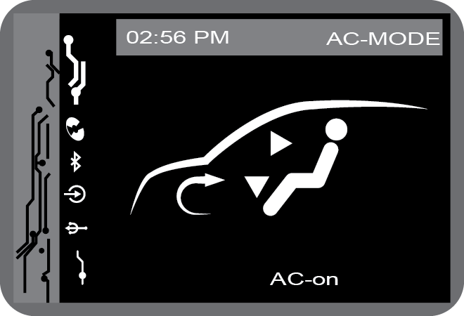
Air is discharged through the foot/floor vents on the instrument panel.
Corresponding information is displayed on the infotainment screen.
10.11.4 Air Distribution - Floor Defrost Mode

Air is discharged through the foot/floor vents, windshield vents and side defrost vents on the instrument panel.
Corresponding information is displayed on the infotainment screen.
10.11.5 Air Distribution - Defrost Mode
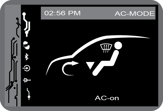
Air is discharged through the windshield vents and side defrost vents on the instrument panel.
Corresponding information is displayed on the infotainment screen.
10.12 Rapid Cabin Cooling
- Make sure that all the windows are fully closed
- Set the blower to maximum speed
- Fully open the vents and adjust louvers to direct air toward face
- Set the air distribution control to face mode
- Set air intake control to fresh air mode
- Turn the air conditioner ON
- Set the temperature control dial to extreme left (coolest) position
For faster cabin cooling you can select re-circulated air intake mode initially. Once passenger compartment reaches a comfortable temperature, shift to fresh air mode. Also blower speed and temperature control knob can be re-adjusted as desired.
If your vehicle was parked in the hot sun with all the windows closed, drive the vehicle with windows open for the first few minutes. This will help in venting the hot interior air out and allow the air conditioner to cool the cabin quickly.
10.13 Rapid Cabin Heating
- Make sure that all the windows are fully closed
- Set the blower to maximum speed
- Set the air distribution control to foot mode
- Set air intake control to fresh air mode
- Set the temperature control dial to extreme right (hot) position
- For de-humidified heating, switch the air conditioner ON
For faster cabin heating you can select re-circulated air intake mode initially. Once passenger compartment reaches a comfortable temperature, blower speed and temperature control knob can be re-adjusted as desired.
In extreme cold weather conditions, the engine coolant takes time to get heated up. Hence it might take a while for hot air discharge, even when blower is running and temperature control dial is set to hot position.
10.14 Front Windshield Defogging/De-misting
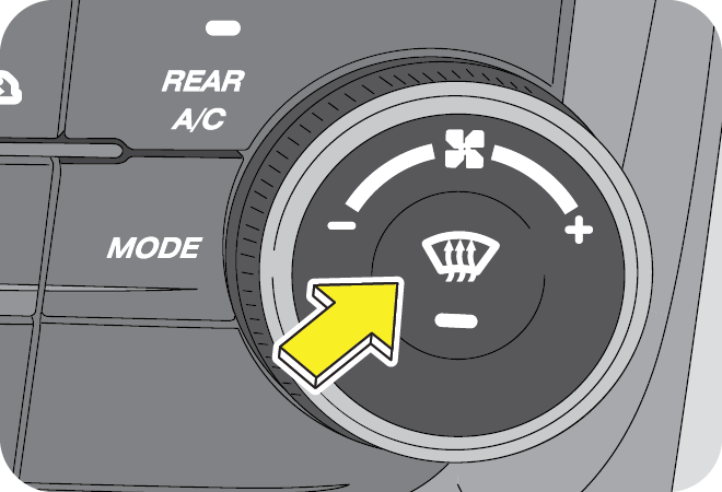
Front windshield glass defogger switch is located on the blower speed control dial in the central switch bank. Press the switch once to activate the defogger. The lamp on the switch illuminates upon activation. AC is turned ON, air is discharged through the windshield defroster vents, side defroster vents and side vents. Air intake mode is switched to fresh air mode automatically. The defogger heats the front windshield clearing the fog/ frost.
Switch OFF the defogger by pressing the switch again as soon as the fog/frost is cleared.
If the windshield defogger switch is not switched OFF manually, it will turn OFF automatically after a pre-defined time, based on ambient temperature.
If you want to switch the defogger ON again, press the defogger switch again.
On second and subsequent activations of the rear windshield defogger in the same ignition cycle, the defogger ON time will be half the duration of the first activation.
10.15 Rear Windshield Defogging/De-misting
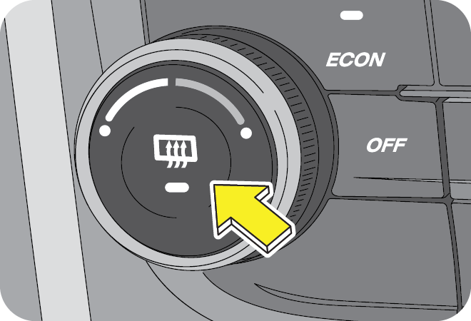
Rear windshield glass defogger switch is located on the temperature control dial in the central switch bank. Press the switch once to activate the defogger. The lamp on the switch illuminates upon activation and the defogger heats the rear windshield clearing the fog/ frost.
Switch OFF the defogger by pressing the switch once as soon as the fog/frost is cleared.
If the windshield defogger switch is not switched OFF manually, it will turn OFF automatically after a pre-defined time, based on ambient temperature.
If you want to switch the defogger ON again, press the defogger switch again.
On second and subsequent activations of the rear windshield defogger in the same ignition cycle, the defogger ON time will be half the duration of the first activation.
10.16 Points to Remember
- For quickly defogging/de-misting/defrosting outside of windshield, it is advisable to operate the windshield wiper/washer for few times intermittently.
- If snow has deposited on windshield, use ice scraper to remove ice deposited before using wiper.
- In freezing weather, warm the windshield with the defroster before using the windshield washer. Also use a washer fluid having anti-freezing properties. These will help prevent the washer fluid from freezing on your windshield.
- Dirty/contaminated windshield would make misting/ fogging-up worse. Always keep the inside and outside of windshield clean.
- Reduced air flow because of clogged HVAC filter or any other obstructions in air flow path may lead to in-adequate defogging/de-misting/defrosting performance. If air flow seems to have considerably reduced, get the filter cleaned or replaced immediately. Air flow path should be kept free of obstructions.
- Reduced cooling performance from air conditioner may lead to in-adequate defogging/de-misting/defrosting. If cooling effect seems to have dropped considerably, get the air conditioning system checked by an authorized Mahindra dealer.
Your vehicle is equipped with a HVAC filter. If the AC performance is considerably low, it is recommended have the HVAC filter checked at the nearest Mahindra dealer.
Never operate HVAC system with the filter removed. This may result in premature failure of system components.
11 TRANSMISSION
The first few shifts on a new vehicle may be somewhat rough. This is a normal phenomenon, and precision shifts will develop within the initial few hundred kilometers of running.
11.1 Gear Lever
Your vehicle is fitted with manual transmission having six forward and one reverse gear. This shift pattern is imprinted on the gear lever knob. The transmission is fully synchronised in all forward gears so shifting to either a higher or a lower gear is easily accomplished. The clutch pedal should be depressed fully while shifting, and then released slowly.
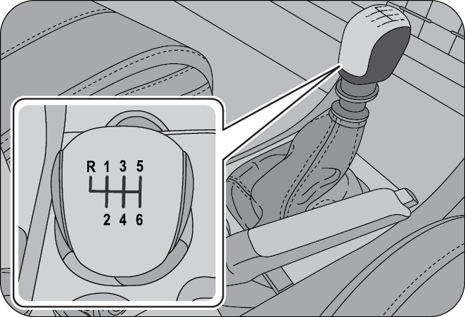
11.2 Gear Indicator
The current gear lever position is indicated in the centre of the speedometer dial.
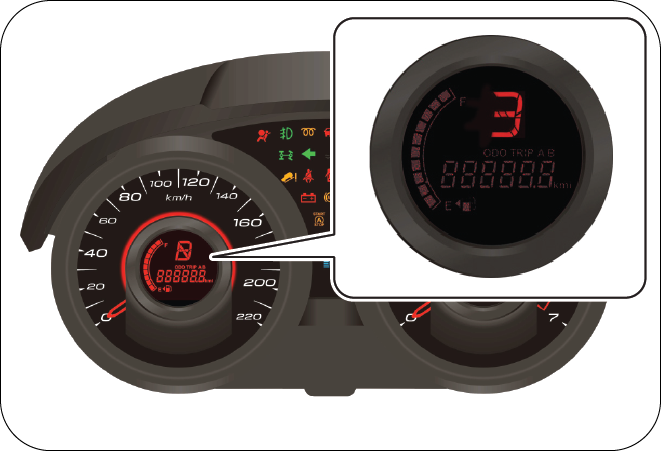
11.2.1 Neutral Position
This position stops the transmission of power from the engine to drive axle. With the gear lever in neutral and brakes released, the vehicle can move freely by pushing or towing. The engine can be started in this mode. It is always recommended to keep the brake pedal depressed in this position. It is advisable to shift into neutral when the vehicle is standstill for longer durations with the engine idling.
Coasting the vehicle with the gear lever in neutral and engine ON/OFF is not recommended. In an event of panic braking, you will not have the power of engine braking to slow down the vehicle. This may lead to personal injury or accident.
Do not leave the vehicle with the gear lever in neutral position. Always engage manual parking brake before leaving the vehicle, to prevent any vehicle movement leading to possible injury to a by-stander or damage to vehicle.
11.2.2 Gears 1-6
Use the gears 1 to 6 as per vehicle load, road/traffic conditions or as per requirement. The current gear selection is indicated in the cluster.
Always depress the clutch fully before moving the gear lever from the current position to any desired position. Perform up-shifts or down-shifts one gear at a time, do not jump gears.
11.2.3 Recommended Gear Shifting Speeds
| Shift Range | Vehicle Road Speed (kmph) |
Engine RPM Range |
|---|---|---|
| 1–2 | 20–25 | 1800–2200 |
| 2–3 | 35–40 | |
| 3–4 | 45–50 | |
| 4–5 | 55–60 | |
| 5–6 | 65–70 |
Shift gears at suitable engine or road speeds to safeguard the transmission components. Avoid driving in high RPM’s (>3000 RPM).
When parking on an incline, gear alone may not be sufficient to prevent the vehicle from moving. Always set the manual parking brake in addition to shifting the gear lever into gear. It is also recommended to turn the front wheels towards the road curb
11.2.4 Reverse
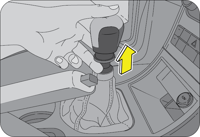
This gear is to enable the vehicle to move in the reverse direction. Move the gear lever into this position only after the vehicle has come to a complete stop and the gear lever is in neutral position.
The reverse lock ring located immediately below the gear shift knob must be pulled upward while moving the shift lever to the reverse (R) position.
To avoid transmission damage, shift into or out of reverse gear only after the vehicle has come to a complete stop and the engine is at idle speed. It is recommended you wait approximately for three seconds in neutral gear before shifting into or out of reverse gear.
For brief stops, e.g. at traffic lights, keep the gear shift in neutral and hold the vehicle with the brake pedal. For prolonged stops, it is recommended to switch OFF the engine and apply the parking brake. When stopping the vehicle on an uphill gradient, do not hold it with the clutch/accelerator; use the brake to avoid unnecessary clutch wear/heat buildup.
Do not leave children unattended in the vehicle or with access to an unlocked vehicle. Children could move the gear lever, which could result in an accident or serious injury.
On slippery/wet road surfaces, never downshift in order to obtain braking action. This could result in a wheel slip and reduced vehicle control.
11.3 Uphill and Downhill Driving
To prevent the engine from laboring at a low RPM when driving uphill gradients or with your vehicle heavily loaded, downshift when necessary to maintain engine RPM within the best torque range. Similarly while driving downhill, downshift to utilize the engine braking in an optimum manner.
12 STARTING AND DRIVING THE VEHICLE
12.1 General Precautions before Starting
- Before starting the vehicle, inspect the inside and outside of the vehicle and look for any damages, leaks, loose parts, foreign objects/debris. Contact an Authorized Mahindra Dealer if required.
- Before starting your journey, check the working of all safety devices/components especially brakes, steering, lamps, signals and tires. In case you suspect any system/ devices not working properly contact Authorized Mahindra Dealer.
- Adjust the seat headrest, steering wheel and fasten the seat belt as described in this manual. Never perform any seat/steering adjustments when the vehicle is in motion.
- Start the vehicle only when seated and belted in the driver's seat.
- Make sure all vehicle occupants are properly seated in their seats and have buckled their safety seat belts. For more information on seat, headrest positioning, seat belts and their proper usage, refer to the “Seat Belts” section in this manual.
- Ensure that the rear view mirror and both the ORVM’s are adjusted for an unobstructed view of the road behind.
- Have someone observe and confirm normal operation of all exterior lamps while you work on the controls from the driver seat. Also, check functioning of all lamps in the instrument panel.
- Check for positive closing, latching, and locking of all doors, both from inside and outside.
- Check the area under vehicle after an overnight parking for fuel, power steering fluid, brake fluid, engine coolant, oil, or other fluid leaks. If leaks are observed, contact an Authorized Mahindra Dealer.
12.2 Pedals
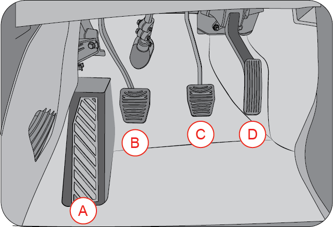
| A | Dead Pedal | C | Brake Pedal |
| B | Clutch Pedal | D | Accelerator Pedal |
12.3 Ignition Switch
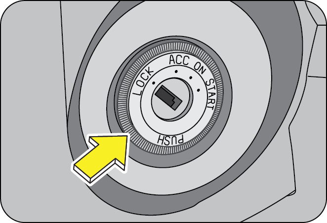
An illuminator ring is provided on the face of the ignition switch to help in locating the ignition switch at night. The ring will illuminate the moment the driver door is opened and will remain glowing till the driver door is closed.
LOCK - This is the ignition and steering lock position. The vehicle circuits and engine is completely switched OFF. The steering wheel is also locked and the key can be removed from the ignition only in this position.
ACC - The steering is unlocked and can be rotated. In this position all electrical circuits are enabled. Use this mode when you want to listen to music, etc., with the engine temporarily switched OFF.
ON - All electrical circuits are enabled. Some of the warning or information lamps illuminate in this position. While some of the lamps will go out after a few seconds, some will continue to remain ON till the engine is started. When the vehicle is being driven, ignition switch remains in the ON position.
Do not leave the ignition in ON when the engine is OFF. This could lead to battery drain and ignition switch damage.
START - This position is to start the engine by cranking the starter motor. This is a momentary position. When the key is turned to start position, the starter cranks the engine. Once the engine is running, release the key, and the key reverts back to ON position and the starter motor disengages from the engine.
Do not continue cranking after the engine has started. This will lead to damage of the starter and other engine components.
If turning the key is difficult, jiggle the steering wheel from side to side and try again.
The key can be removed only in the LOCK position. When the key is removed, the steering column lock is activated and the steering wheel cannot be turned.
Never return the key to the LOCK position or try to remove the key, when the vehicle is in motion. Removing the key allows the steering wheel to lock. You will loose the control of the vehicle and may cause serious accident. Remove the key only when the vehicle is parked.
12.4 Starting the Engine
- Shift the gear lever to neutral position.
- Apply parking brake.
- Turn the ignition ON.
- Do not press the accelerator.
- Turn the key momentarily to the START position to crank the engine.
- Once the engine starts, release the key; it will return to the ON position
- If the engine fails to start, attempt to restart after about 10 seconds
- If the engine fails to start even after repeated attempts as per the procedure given above, contact the nearest Authorized Mahindra Dealer.
Do not continue cranking after the engine has started. This will lead to damage of the starter and other engine components.
To prevent damage to the starter, wait 10 seconds before attempting to restart the engine.
If the vehicle battery has discharged, use booster cables, a booster battery or a battery from another vehicle to start. Jump-starting a vehicle can be dangerous if done improperly. Refer to the “Jump starting procedure” section in this manual.
12.5 Engine Idling
The idle speed is controlled automatically and it will decrease as the engine warms up.
Observe that all warning lamps are OFF when the engine is running.
After idling for a few seconds, follow the below steps to drive away;
- Release the parking brake
- Depress the clutch
- Shift the gear lever to 1st gear
- Release the service brake pedal
- Drive by releasing the clutch and depressing the accelerator pedal simultaneously.
12.5.1 Engine Idling - In Cold Weather
Avoid full throttle operation when the engine is cold and prolonged idling at low ambient temperatures. Long periods of idling may be harmful to your engine. Combustion chamber temperatures can drop so low that the fuel may not burn completely. Incomplete combustion allows carbon and varnish to form on piston rings and injector nozzles. Also, the unburned fuel can enter the crankcase, diluting the oil and causing rapid wear to the engine.
You must fuel this vehicle with Ultra Low Sulfur Diesel. For smooth functioning and reliable operation of the engine during cold weather conditions, use winter diesel for refuelling which is available at filling stations during winter months. Check with your fuel retailer for details.
The recommended engine coolant mixture will work fine till ambient temperatures do not drop below -32ºC approx. For ensuring above performance, it is a must that you use only recommended engine coolant.
12.6 Stopping the Engine
Your vehicle is powered by a turbo diesel engine. Before turning the engine OFF, always allow the engine to return to normal idle speed by running for few seconds.
This assures proper lubrication of the turbocharger. This is particularly necessary after any hard driving.
Follow the below steps for switching the engine OFF;
- Keep your right foot on the service brake pedal
- Firmly engage the parking brake
- Move the gear lever to the neutral position
- Slowly release the service brake pedal
- Turn front wheels towards the road curb
- Turn the key to the steering lock position and remove
- Lock your vehicle when leaving
12.7 Exhaust Gases
Protection against exhaust gas entry into the vehicles interior is considered in the design of the exhaust system.
- Vehicle exhaust contains Carbon Monoxide, Carbon Dioxide, Nitrogen Oxides, Hydrocarbons and Particulate Matter. These are potential environmental and health hazards.
- Avoid inhaling the exhaust gases. Carbon Monoxide is a colorless and odorless gas and can cause unconsciousness or even death.
- If the exhaust system is damaged for any reason or you notice a change in the exhaust noise, have the vehicle checked by an Authorized Mahindra Dealer immediately.
- Do not start the vehicle in a closed garage or in an enclosed area where ventilation is poor for the exhaust gases.
- Since the engine compartment and exhaust system components are hot and can ignite a fire, do not park or leave the vehicle with the engine idling over dry grass, leaves, paper, rags or any combustible material.
Never keep the engine running when the vehicle is parked in an area which is not properly ventilated. This could lead to serious respiratory problems and/or death.
12.8 General Driving Precautions
Always observe the following precautions to minimize the risk of accidents leading to serious personal injury or damage to your vehicle.
- Before you drive your vehicle, please read this manual carefully.
- When you start driving, verify proper operation of the brakes and steering system.
- If, while driving, you hear any strange noise or feel unusual vibration, or if you have any concerns whatsoever, or if any warning lamps illuminate or buzzers sound, park/stop the vehicle in a safe location as soon as possible. Identify the cause and take any necessary remedial action. Contact your Authorized Mahindra Dealer if necessary.
- Never overload or improperly load your vehicle.
- Always be attentive while driving and follow safe driving practices.
- Always maintain the recommended inflation pressure in tires.
- Always drive at a safe speed appropriate for given driving conditions. You must follow the speed limits.
- While backing up, keep a constant lookout for people, particularly children, or other obstructions or hazardous material that might be present behind the vehicle.
- Avoid loading any items on the roof that will raise the vehicles centre of gravity and make your vehicle more unstable.
- Loaded vehicles, with a higher centre of gravity, may handle differently than unloaded vehicles. Extra precautions, such as slower speeds and increased stopping distance, should be taken when driving a heavily loaded vehicle.
- Always slow down in gusty crosswinds. Because of its profile and higher centre of gravity, your vehicle is more sensitive to side winds than an ordinary passenger car. Slowing down will allow you to have much better control.
- When driving off-road or on rugged terrain, do not drive at excessive speeds, jump, make sharp turns, strike objects, etc. This may cause loss of control or vehicle rollover causing serious injury. You are also risking expensive damage to your vehicle's suspension and chassis.
- Maintain steering wheel control at all times, especially on rough terrains. Sudden changes in terrain can result in abrupt steering wheel motion. Make sure you grip the steering wheel from the outside. Do not grip the spokes.
- If the vehicle goes from one type of surface to another (e.g. from concrete to gravel/sand/mud/snow) there will be a change in the way the vehicle responds, especially the way it responds to steering, braking and accelerating inputs.
- Be extremely careful when driving on pavements made slippery by loose sand, water, gravel, snow or ice.
- If your vehicle goes off the edge of the pavement, slow down, but avoid severe brake or steering application. Ease the vehicle back onto the pavement only after reducing your speed. Do not turn the steering wheel too sharply while returning to the road surface.
- It may be safer to stay on the apron or shoulder of the road and slow down gradually before returning to the pavement. You may lose control if you do not slow down or if you turn the steering wheel too sharply or abruptly.
- In an unavoidable emergency situation where a sudden sharp turn must be made, turn the steering wheel only as rapidly and as far as required to avoid the emergency. Excessive steering will result in less vehicle control. Additionally, smooth variations of the accelerator and/or brake pedal pressure should be utilized if changes in vehicle speed are called for. Avoid abrupt steering, acceleration or braking which could result in an increased risk of loss of vehicle control, vehicle rollover and/or personal injury. Use all available road surfaces to return the vehicle to a safe direction of travel.
12.9 Off Road Driving Precautions
- When driving off-road or on rugged terrains, never over speed or make sharp turns. This may cause loss of control or vehicle rollover causing serious injury.
- Maintain steering wheel control at all times. Sudden changes in terrain can result in abrupt steering wheel motion.
- Do not drive horizontally or diagonally across steep slopes, your vehicle can tip over sideways. Driving straight up or straight down is preferred.
- Drive cautiously to avoid vehicle damage from concealed objects such as rocks and stumps. You should either know the terrain or map-out your route before driving in the area.
- Always perform a maintenance inspection after each day of off-road driving that has taken you through rough terrain, sand, mud or water.
Off-road operation puts more stress on your vehicle than does most on-road driving. Always perform a maintenance inspection after each day of off-road driving that has taken you through rough terrain, sand, mud, or water.
- After going off-road, it is always a good idea to check for damage. Completely inspect the underbody of the vehicle for any damages.
- Check for accumulations of plants or bushes. These could be a fire hazard. They might also hide damage to fuel lines, brake tubes/hoses, etc.
- Inspect all the tubes/hoses and check for any fluid leakages.
- Get heat exchangers (radiator and condenser) cleaned.
- Check threaded fasteners for looseness, particularly on the chassis, drive train components, steering, suspension and brakes. Retighten them, if required, and torque to the values specified in the ‘Repair Manual’.
- If any unusual vibration is experienced, check the wheels for impacted material. Impacted material can cause a wheel imbalance. Get it inspected/corrected as soon as possible.
- After driving through deep water, inspect your vehicle fluids and lubricants (engine oil, transmission/transfer case/axle oils) to ensure the fluids have not been contaminated.
12.10 Driving Through Water
Although your vehicle is capable of driving through shallow water, there are a number of precautions that must be considered before entering the water.
- The ground under the water might not be firm which could result the water being deeper than expected when driving the vehicle through it.
- Do not stop or shut OFF the engine while immersed in water. It helps in preventing water getting inside the exhaust pipes.
- When backing down a ramp, do not allow the exhaust tail pipe to immerse in water.
- Water can wash the grease from wheel bearings, causing rusting and premature failure. It may also enter the differentials, transmission and transfer case, reducing the oil's lubricating qualities. If these are submerged in water, the lubricants should be replaced as required.
- Water entering the transmission will cause deterioration in shift quality, locking up of your transmission accompanied by vibration, and ultimately damaging the transmission.
- Sand, mud/sludge that has accumulated in brake drums and around brake discs may affect braking efficiency. This may also damage brake system components. Wet brakes cannot stop the vehicle as effectively as dry brakes. Drying can be improved by driving the vehicle slowly while applying light pressure on the brake pedal.
- When driving through water, traction or brake capability may be limited. Always perform a maintenance inspection after each day of off-road driving that has taken you through water.
- If the water is swift flowing and rising (as in storm run-off) avoid crossing until the water level recedes and/or the flow rate is reduced.
- The flowing water can erode the streambed causing your vehicle to sink into deeper water.
- Determine the exit point(s) that are downstream of your entry point to compensate for drifting.
Never drive through still water that is higher than the bottom of the axle hubs. Not following this instruction will allow water to enter vehicle components causing internal damage to the components, affecting driveability, safety, emissions and reliability.
When driving through water, drive very slowly and at constant speed, less than 5 kmph. Water waves generated will be high and may enter air intake, causing severe engine damage or cause a vehicle to get stalled
You must slow down while driving through shallow water. Speeding may cause water to splash onto the windshield, impairing your vision.
12.11 Tips for Better Fuel Economy
Give due consideration to the points listed below for better performance of vehicle and enhance fuel economy.
- Smooth, moderate operation can yield savings in fuel
- Steady speeds without stopping will usually give the best fuel economy
- Idling for long periods of time may waste fuel
- Anticipate stopping; slowing down may eliminate the need to stop
- Sudden or hard accelerations may reduce fuel economy
- Slow down gradually
- Drive at moderate speeds
- Revving the engine before turning it off may reduce fuel economy
- Air conditioner may reduce fuel economy
- Warming up a vehicle on cold mornings is not required and may reduce fuel economy
- While idling put the gear lever in neutral position
- Resting your foot on the brake pedal while driving may reduce fuel economy
- Combine errands and minimize stop-and-go driving
- Keep tires properly inflated
- Use recommended engine oil. Refer to the Maintenance Section for specifications and capacities
- Follow the recommended maintenance schedule and perform owner maintenance checks recommended
- Heavily loading a vehicle or towing a trailer will reduce fuel economy
- Carrying unnecessary weight may reduce fuel economy
- Adding certain accessories to your vehicle may reduce fuel economy
- Four-wheel-drive operation (if equipped) is less fuel efficient than two-wheel-drive operation
- Driving on flat terrains offer improved fuel economy as compared to driving on hilly terrains
- Close windows during high speed driving for better fuel economy
12.12 All Wheel Drive (AWD) Operation (if equipped)
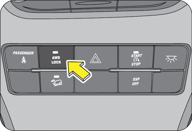
In an AWD vehicle, power is transmitted to all the wheels. This is managed by the AWD System which intelligently transfers torque to all four wheels. AWD system includes electromagnetically operated clutch which is controlled by an ECU. According to the driving conditions this system automatically delivers torque to the rear wheels.
12.12.1 AWD System
AWD system is available in two operating positions viz., AUTO mode and AWD LOCK mode.
Once the ignition key is turned ON, AWD system by default turns into AUTO mode. In AUTO mode, whenever a slippage is detected in the FRONT wheels (slippery surfaces like icy roads, wet surfaces, etc.) the torque is transferred to the REAR wheels by the AWD system.
12.12.2 AWD Lock
AWD LOCK button is located on the central bezel switch bank. The LED on the switch turns ON when the AWD Lock is activated. In this mode fixed amount of torque is transferred to the rear wheels irrespective of the driving condition.
AWD vehicles have to be towed only with the rear wheels lifted off the ground or on all four wheels. If vehicle needs to be towed by lifting the front wheels, then the propeller shaft needs to be disconnected in order to protect the coupling.
12.13 Electronic Stability Program (ESP) (if equipped)
This system enhances directional control and stability of the vehicle under various driving conditions. The ESP corrects for over-steering and under steering behavior of the vehicle by applying the brake of the appropriate wheel automatically. Engine power may also be reduced to assist in counteracting the condition of over-steer or under-steer and help the vehicle maintain the desired path.
ESP uses steering angle sensors and YAW rate sensor to determine the path that the driver intends to steer the vehicle and compares it to the actual path of the vehicle. When the actual path does not match the intended path, the ESP applies the brake of the appropriate wheel to assist in counteracting the condition of over-steer or under-steer.
Over-steer - when the vehicle is turning more than appropriate for the steering wheel position.
Under-steer - when the vehicle is turning less than appropriate for the steering wheel position.
The ESP cannot prevent the natural laws of physics from acting on the vehicle, nor can it increase the traction afforded by prevailing road conditions. The ESP cannot prevent accidents, including those resulting from excessive speed in turns, driving on very slippery surfaces, or hydroplaning. Only a safe, attentive, and skillful driver can prevent accidents. The capabilities of an ESP equipped vehicle must never be exploited in a reckless or dangerous manner that could jeopardize the user’s safety or the safety of others.
12.13.1 ESP ON
Whenever the vehicle is started, the ESP system will be in active mode. This mode should be used for most driving conditions.
When the ESP is operating, you can feel a slight pulsation in the vehicle. This is only the effect of brake control and indicates nothing unusual.
When moving out of the mud or slippery road, accelerator response may be different because ESP system controls the engine rpm to come out this slippery road condition. This is normal.
12.13.2 ESP OFF

In some driving conditions, to maximise traction, it may be beneficial to de-activate ESP.
Such conditions are;
- To start in deep snow or on a loose surface
- Driving in deep sand
- Driving through deep mud etc.
Press ESP OFF button again to activate ESP function.
Mahindra recommends that ESP be operational in all normal driving conditions.
When ESP is in OFF mode, other functions like HHC (Hill Hold Control) HBA (Hydraulic Brake Assist), HDC (Hill Descent Control), DTC (Drag Torque Control), ROM (Roll Over Mitigation) will be in working mode.
However for safety reasons, if the ESP system detects that the vehicle is going into a unstable condition, ESP will be automatically activated on depressing the brake pedal
ESP, by default, will be in ON condition for every ignition cycle.
12.14 Hill Descent Control (HDC) (if equipped)
- Assists the driver to descend a steep hill (max 50% inclination) by means of brake intervention limiting the vehicle speed is without driver's input.
- During HDC if the wheel slip becomes excessive, ABS will be activated automatically.
- HDC is a user intended function. To activate press HDC button on the central bezel switch bank. The LED on the button illuminates indicating the status. Press the button again to de-activate HDC.
- During a descent, if the vehicle speed is more than the rated speeds (refer recommended shift speeds), HDC (if selected) automatically operates the brakes to slow the vehicle and maintain a speed relative to the selected gear and the accelerator pedal position.
- HDC will also work in neutral gear, and maintains the vehicle rolling speed by operating brakes automatically. HDC will deactivate automatically, if the vehicle speed is more than 45 kmph.
- While HDC is controlling the vehicle speed, descent speeds can be varied using cruise control switches mounted on the steering wheel.
- To decrease speed, press and hold “SET -” button. The vehicle speed at the point of switch release will become the new descent speed.
- To increase, press and hold “SET +” button. The vehicle speed at the point of switch release will become the new descent speed. Alternatively, descent speeds can be adjusted by tapping the “SET _” or “SET +” buttons. Each press of the button will adjust the speed by approximately 0.5 kmph.
The descent speed increases only if the gradient is sufficiently steep to cause the vehicle to accelerate as the braking effect is reduced. On a shallow slope, pressing the “SET +” button may result in no speed
If the brake pedal is depressed when HDC is active, HDC is overridden and the brakes will perform as normal (a pulsation might be felt through the brake pedal). If the brake pedal is then released, HDC will recommence operating if necessary.
HDC system monitors the brake temperature continuously. If brake application is continuous and brake temperatures are too high, HDC de-activates automatically. This is to ensure that the brake pads are not worn due to continuous brake application.
12.15 Hill Hold Control (HHC) (if equipped)
Hill Hold Control with acceleration sensor identifies gradients and holds the vehicle for about three to four seconds after the brakes have been released in order to prevent the vehicle from accidentally rolling backwards during a hill start.
Imagine a situation where your vehicle is stopped on an uphill incline. If you release the brake while moving off, there are chances that your vehicle may roll back. HHC helps in such situations by holding the vehicle from rolling back.
HHC operation cannot be intervened. For HHC to work, clutch pedal must be in fully pressed condition and gear engaged.
12.16 Cruise Control
Cruise control allows you to maintain a set speed without the need to keep your foot on the accelerator pedal. It should be used for cruising on straight, open highways. Never use it for city driving, inclines, winding roads, slippery roads, heavy rain or in bad weather conditions.
It works on the closed loop system principle to maintain the set speed of the vehicle; the system controls the fuel injection of the engine in order to maintain the set speed.
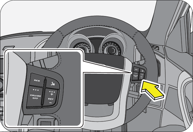
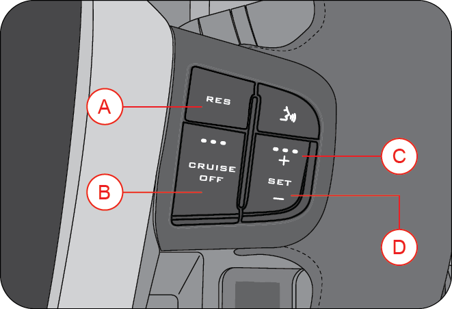
| A | Resume | C | SET + |
| B | Cruise Off | D | SET- |
Cruise control enhances your comfort while driving and allows you to effortlessly maintain the desired lane speed limit. Improper use of the cruise control can lead to an accident.
Cruise control is designed to operate above a vehicle speed of 20 kmph for all gears except 1st and reverse gears. The cruise lamp in the instrument cluster functions only if the cruise control is active.
- The vehicle is cruising above 20 kmph.
- Engine RPM above 1200 RPM.
- Vehicle is in any gear except 1st and reverse.
- Clutch pedal released.
- Brake pedal released.
- Cruise is activated first time in an ignition cycle by SET+ /SET- button.
- Subsequent cruise engagements can be done by RESUME SET+ /SET- buttons in the same ignition cycle.
- CRUISE OFF button is pressed.
- Brake or clutch pedal depressed.
- If the vehicle speed exceeds the cruise set speed by 30 kmph by accelerator pedal intervention.
- If vehicle speed is increased by 10 kmph for more than 30 sec. by pressing the accelerator pedal.
- When Set+/Set- switch is pressed for more than 12 sec. (In this case vehicle will not go into cruise mode in that ignition cycle. In order to restore the cruise function switch OFF the ignition, wait for 30 sec. and switch ON the ignition)
- Cruise influencing error indicated by Check Engine Lamp, OBD lamp, etc.,
12.16.1 Cruise Control Activation
Drive the vehicle to the desired cruising speed (any value greater than 20 kmph), press and hold the SET+ button until the cruise lamp in the instrument cluster illuminates.
If cruise is deactivated (eg. by depressing brake to handle an intervention in the road etc.,) in current driving cycle, reactivate the Cruise to the last active Cruise Speed by pressing the RESUME button.
Cruise control may not hold the set speed when you are going up or down hills, and the vehicle may come out of cruise control. This is indicated by the cruise lamp going OFF in the instrument cluster.
12.16.2 Cruise Control De-activation
You can cancel cruise control in any of the following ways;
- Press the CRUISE OFF button in the steering wheel.
- Press the brake pedal.
- Gear selector moved into neutral.
- HDC or ESP becomes active.
12.16.3 SET+ Button
SET+ button is used to activate cruise control and also to increase the cruise set speed.
To increase the speed in very small amounts, press the SET+ button. Each time you press, the cruise set speed increases by about 2 kmph. When you wish to continuously increase the cruising speed, press and hold the SET+ button and release when the desired speed is reached.
12.16.4 SET- Button
To decrease the speed in small amounts, press the SET - button. Each time you press, the cruise set speed decreases by about 2 kmph.
When you wish to continuously decrease the cruising speed, press and hold the SET- button. When the desired speed is reached, release the button.
If switch is pressed for more than 12 secs, the switch is assumed to be malfunctioning and the cruise functionality ceases to function in that ignition cycle. To resume functionality, ignition has to toggled.
The cruise control is a convenience system designed to assist the driver during vehicle operation. The driver must at all times remain alert of road/traffic conditions and responsible for the vehicle brake operation / steering control.
Never activate cruise control in traffic or when driven in adverse road conditions (heavy rains, windy, slippery etc.)
12.16.5 RESUME Button
With the help of RESUME, you can opt for the previous set cruising speed of the vehicle in the same ignition cycle. This is best explained with the following example:
- Assume, you have activated cruise mode and set the vehicle speed at 50 kmph.
- Due to an obstacle or a sharp turn, you have deactivated the cruise mode either by pressing the brake pedal or by switching OFF the CRUISE control.
- Vehicle comes out of the cruise mode.
- When the road condition is suitable to switch over back to cruise control mode, press RESUME button once. The system activates the cruise control mode to the previous cruising speed of 50 kmph.
- To resume the previous cruise set speed, the vehicle speed should be above 20 kmph.
12.16.6 Override Function
This function enables user to ramp up the cruising speed to overtake front vehicle.
The cruising speed can be increased by using accelerator pedal. User has to complete this action within 30 seconds, to maintain the cruise mode. If user exceed the 30 seconds limit, cruise mode will be deactivated.
12.17 Reverse Parking Assistance System (RPAS) (if equipped)
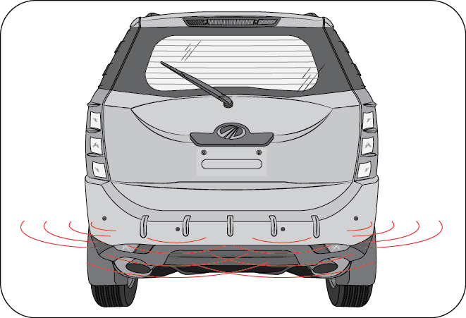
Intellipark Reverse Assist System is a system which aids the driver while reversing the vehicle at a speed less than 5 kmph.
On taking the vehicle in reverse, the system detects obstacles behind the vehicle within the sensing zone and which cannot be viewed by internal rear view mirror and the outside rear view mirrors, and indicate the driver with the distance and direction of the detected obstacle along with the alert sound which proportional to the distance. The smaller the distance shorter the interval between the beeps.
Magnetic devices present in the detection range could vastly affect the sensor performance and the distance displayed may not be accurate.
12.17.1 RPAS Sensors
Four RPAS sensors are provided on the rear bumper to give a complete view behind the vehicle to the driver.
12.17.2 Engaging and Disengaging of RPAS
- Engine should be running to engage reverse parking assistance system
- RPAS will be activate automatically when reverse gear is engaged and deactivate when reverse gear is disengaged
12.17.3 RPAS Information on Infotainment Screen
RPAS display on infotainment screen gives the following information;
- Left zone indicates obstacle on left hand side.
- Centre zone indicates obstacle in the centre.
- Right zone indicates obstacle on right hand side.
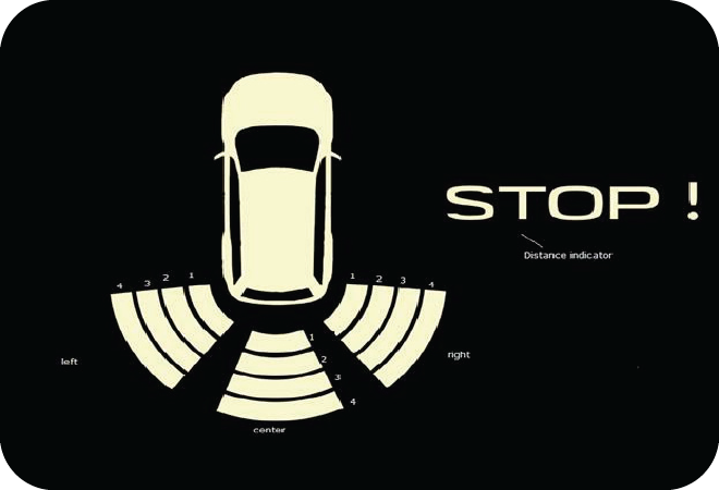
Display bars 1, 2, 3 and 4 indicate how close the obstacle is from the vehicle rear bumper, with bar 1 being very close and bar 4 being distant.
Distance indicator will display a STOP symbol if the obstacle is less than 50 cm from the vehicle rear bumper.
12.17.4 Operation of RPAS
- Start the vehicle
- Engage the gear in reverse - RPAS will be displayed in the infotainment screen
- Start moving the vehicle in reverse direction
-
Display bars in the respective direction will glow according to obstacles in its path.
- If the obstacle is between 100 to 120 cm, bar 4 will be turned ON
- If the obstacle is between 75 to 100 cm, bars 3 & 4 will be turned ON
- If the obstacle is between 50 to 75 cm, bars 2, 3 & 4 will be turned ON
- If the obstacle is less than 50 cm, all bars in that direction will be turned ON and a STOP symbol will be displayed
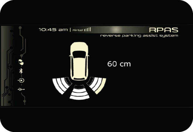
- Distance indicator will display the distance in multiples of 2 cm, whichever is shortest
- The alert sound can be heard from the driver side speaker. Frequency of the beep will increase if obstacle comes closer (crossing each display bar) and the sound will be continuous if any of the obstacle is less than 50 cm.
- Optical indication will be displayed without any obstacle once the gear is shifted from reverse to any other gear, for 10 seconds or until the vehicle reaches 10 kmph (whichever is earlier)
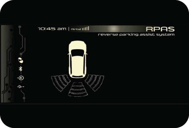
For Example; assume 3 obstacles are placed as mentioned below;
- Obstacle at left at 110 cm
- Obstacle at centre at 80 cm
- Obstacle at right at 60 cm
On engaging reverse, infotainment display is as below;
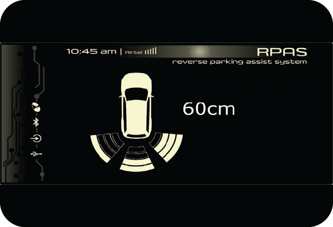
Since obstacle is at 60cm in right - minimum distance is shown in the distance indicator.
Along with this, a beep sound can be heard from driver side speaker. Frequency of the beep will increase if obstacle comes closer (crossing each zones) and the sound will be continuous if any of the obstacles is less than 50 cm.
12.17.5 Important
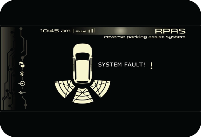
- If display bars in any one or all of the sides are displayed with cross marks, contact an Authorized Mahindra Dealer.
- Obstacle in the blind zone (between the sensors nearer to the rear bumper) cannot be sensed by the system.
- Please check the condition of the obstacle behind your vehicle before reversing. In some cases, the display may be not as same as reality due to the installed sensor level, obstacle shape, reflection condition.
- System cannot sense the wire mesh, handrail, small objects and some obstacles which are coming below the bumper level.
- System cannot sense obstacles like cotton or spongy surface which absorb ultrasonic waves.
- System performance is dependent on the reflection angle of the obstacle
- System may give wrong signal on reversing the vehicle on grasslands and bumpy roads
- System may give wrong signal while vehicle moving from plain ground to sloppy ground or vice versa.
- System may give wrong signal by sensing the ground when the bumper is tilted more from the normal position or when the vehicle is heavily overloaded.
- System may give false alarm during heavy rain, windy or snow conditions.
- Clean the sensors and make them free of ice, dust, water etc. for proper working of the system.
- System will not work properly if the sensor orientation is changed.
- System will not sense pot holes, trenches or drainage which are below the ground level.
- Any sort of paint or any adhesive on the sensor faces will not guarantee the proper functioning of the system.
- Applying pressure on sensor face may deteriorate the system performance, so care should be taken while replacing sensors. In the event sensor found damaged kindly don't attempt to replace them by yourself, bring to the notice of your dealer.
- Bumper covered with guards and other accessories may not allow sensors to function properly.
This system is an aiding system and it should not replace the need to drive carefully. Under no circumstances will the manufacturer accept any responsibility or can be held liable for any direct or indirect, incidental or consequential damage caused by this system
12.18 Stop/Start System (if equipped)
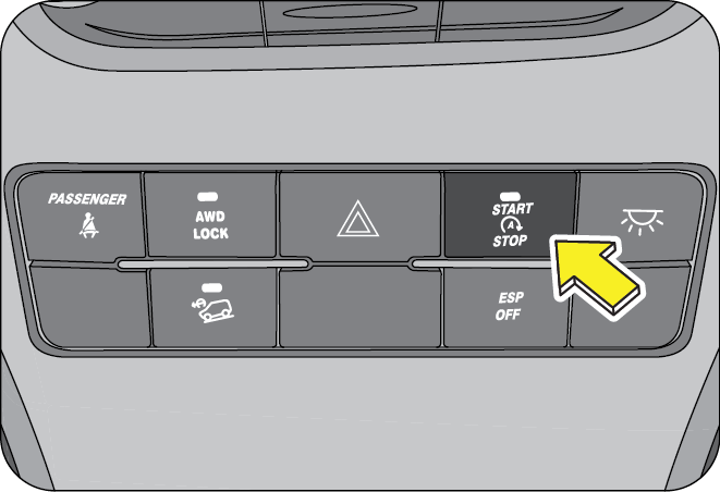
Stop/Start system automatically “stops” and “starts” the engine when idle at signals or long traffic jams. This in turn gives a better fuel efficiency. Stop/Start system is activated by the “Stop/Start” button in the central bezel switch bank. The LED on the button indicates the status of the button.
12.18.1 How Does the Stop/Start System Work?
Let’s take a simple example of driving in traffic conditions within your city. Assume that your vehicle has stopped at a traffic junction due to a red signal. The following steps illustrate how the system functions.
- The vehicle has come to a halt at a traffic signal, is in the neutral gear and the clutch pedal is released
- The “Stop/Start” lamp in the cluster will blink indicating that the engine is going to stop shortly. The engine will shut down automatically after a specific time period
- The “Stop/Start” lamp will illuminate in the instrument cluster indicating the engine was stopped by the Stop/ Start System
- Once the signal turns green, press the clutch pedal and the engine starts immediately
- The indicator in the cluster goes OFF indicating that the engine has started again and you are ready to drive on
- Stop/Start System is activated using the Stop/Start button
- Bonnet is fully closed
- In the current ignition cycle, the vehicle has crossed 2 kmph at least once
- Current status of the engine is idling
- Vehicle speed is zero
- Accelerator pedal and clutch pedal are fully released
- Vehicle battery should be in healthy condition
- Engine is warm (Engine coolant temperature is between 25 °C and 100 °C). This is an extra precaution to ensure safe working of the engine
- Fuel temperature is less than 60 °C
- Gear in neutral
- Vehicle should have been stopped by the Stop/Start System
- Gear lever is in the neutral position, Clutch pedal is fully de-pressed
- Vehicle speed is zero
- Stop/Start System is in active state
- Bonnet should be closed
12.18.2 Overview of the Stop/Start System
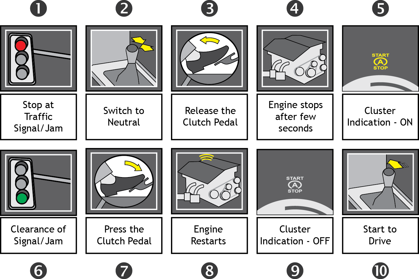
12.18.3 Frequently Asked Questions (FAQ)
- What is the advantage of the system?
- The Stop/Start System aids in attaining better fuel efficiency on your vehicle and thus reducing your running costs. However, the mileage improvement will depend upon various parameters such as prevailing traffic, driving patterns, etc.
- What are the other advantages of the system?
- Since the engine is switched off during traffic signals/ jams, considerable amount of CO2 release to the atmosphere is avoided. This reduces global warming and thus provides us with a cleaner atmosphere to live
- Ability to start the engine by pressing the clutch pedal
- Reduces noise pollution at traffic signals
- Is it possible to start the engine through the clutch pedal for the first time?
No, the engine can be cranked only with the ignition key for the first time. If the engine is stopped automatically by the system, only then it is possible to start the engine through clutch pedal.
- How to activate/deactivate the system?
The system is activated by default during every ignition cycle. The LED indication on the Stop/Start switch indicates the status of the system. The system can be turned OFF or back ON using the Stop/Start switch.
- Whether the system will get activated as soon as the engine is started the first time with the ignition key?
No, the Stop/Start system can be activated only by the Stop/Start switch, provided all listed conditions (in the previous section) are met. This is to ensure better performance of the engine in terms of fuel economy and durability.
- What is to be done, if I don’t want the system to stop my engine at traffic signals/Jams?
The system can be turned OFF by the Stop/Start button in the central bezel switch bank.
- Whether the A/C will function, if the engine is switched off?
No, the A/C will not work. However the blower will be in operation when the ignition is ON.
- What will happen if I keep the clutch continuously pressed at traffic signals/jams?
The system will not stop the engine if the clutch is continuously pressed since it indicates the driver’s intention of moving the vehicle immediately.
- When the battery charge is low, whether the engine will be switched off?
If the battery charge drops below a certain threshold level, the system will not stop the engine so as to preserve the battery from further draining.
- Whether I will be able to operate the engine with the normal ignition key?
Yes, normal operation with the ignition key is always possible.
- Whether the vehicle will start (or) stop in gear?
The vehicle will not start or stop automatically in gear to ensure safety. It will do so only in the neutral position of the gear lever.
- Whether the system will stop my engine in moving traffic?
No, the engine will be stopped only when the vehicle speed is zero.
- Whether the audio system will be switched OFF, when the engine shuts down?
No, the audio system will not be switched OFF and you can continue to enjoy the music.
- Whether the engine will re-crank whenever the clutch pedal is pressed?
No, when the engine is running, the starter motor will not attempt to re-crank.
- If any component involved in the system fails, what will happen?
The system has a built-in diagnostic module which understands the failure and immediately goes to bypass mode. In the bypass mode the engine can be turned ON and OFF by ignition key as usual.
12.19 Fuel

Use only commercially available vehicular Ultra-low Sulfur Highway Diesel that meets the BIS standard (Conforming to IS 1460;2010 BSIV/BSIII specification or equivalent). Information on diesel quality can normally be found in the fuel pump. Please contact filling station personnel in case labels in the pump cannot be found.
Do not fill the fuel tank or mix the fuel with gasoline, alcohol based fuels, kerosene, etc. This will damage the engine, fuel and exhaust system components.
If you have accidentally filled the fuel tank with incorrect or non-approved fuel, do not start the vehicle. Contact an Authorized Mahindra Dealer to have the fuel system drained completely.
12.19.1 Fueling during Winter
During freezing weather if fuel is not winterized or is insufficiently winterized, waxing/gelling may start in fuel, leading to interruption in fuel supply to engine. For smooth functioning and reliable operation of the engine during cold weather conditions, use winterized ULSD which are available at the filling stations during winter months. Check with your fuel retailer for further details.
Avoid inhaling fuel vapors and any skin or clothing contact. Direct skin contact with diesel or the inhalation of fuel vapor may affect your health
Diesel is highly flammable and poisonous. It burns violently and can cause serious injury. Never allow sparks, flames or smoking materials near diesel. Turn OFF the engine before refueling. Whenever you are around diesel, extinguish all smoking materials.
12.19.2 Minimum Fuel Requirement
It is recommended maintaining a minimum of 10 liters of fuel in the fuel tank. Driving the vehicle till the fuel tank is empty is not recommended. Always have sufficient fuel in the tank. Check the fuel level prior to starting your journey.
Never carry fuel in separate containers in the vehicle, it is dangerous and may lead to inadvertent fuel leak or spillage.
12.19.3 Fuel-Lid Opening and Closing
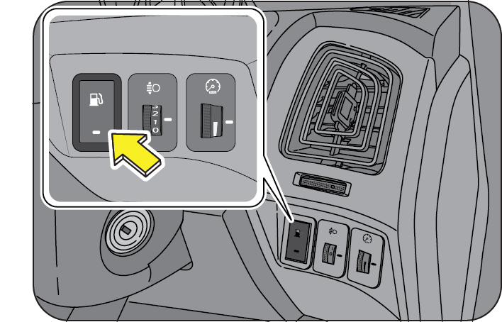
The remote fuel-lid can be opened by gently pressing the fuel lid button (adjacent to the head lamp leveling switch) on the instrument panel driver side.
Fuel filler lid cannot be released when the vehicle speed is more than 20 kmph.
Fuel filler lid operation is limited to 8 times / minute. Avoid unnecessary usage of fuel filler lid button.
Turn the fuel cap counter-clockwise to open. Refuel and put the cap back in its place and tighten in the clockwise direction till three distinct clicks are heard. Close the fuel lid shut. 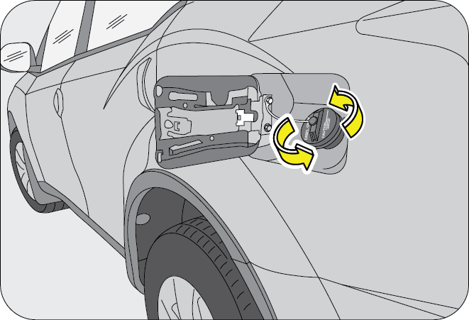
Ensure the fuel cap and lid are securely closed before starting the vehicle.
12.19.4 Mechanical Override for Fuel Lid Opening
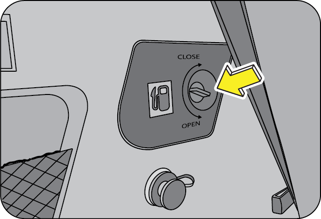
In the unlikely event of remote switch not opening the fuel lid, a mechanical over ride release is provided. It is located in the luggage compartment LH trim area behind the third row seats. Turn the knob anti-clockwise to open the fuel lid.
13 WHEELS AND TYRES
13.1 Tyre Information
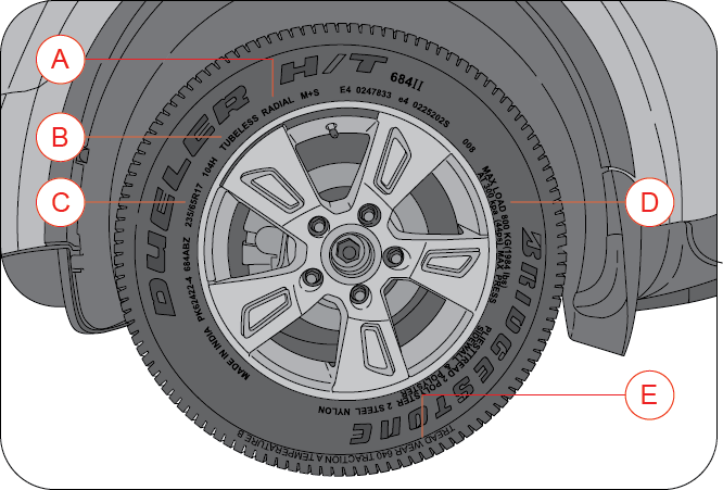
| A | RADIAL TYRES OR BIAS-PLY TYRE. |
| B | “TUBELESS” OR “TUBE TYPE” |
| C | TYRE SIZE |
| D | MAX LOAD LIMIT |
| E | TREAD WEAR |
13.2 Tyre Rating
Your vehicle is originally equipped with tyres supplied by a reputable manufacturer. If you ever have any questions regarding your tyres, please refer to literature supplied by the tyre manufacturer, or to the separate tyre warranty provided by the tyre manufacturer. You may also contact Mahindra directly, or the tyre manufacturer.
The tyre rating of XUV500 is;
- 235/65 R17 104H
Tyre rating is explained as below;
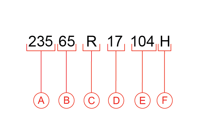
Callout (A): 235 (Three-digit number): This number gives the width in millimeters of the tyre from sidewall edge to sidewall edge. This is called as “Section Width”.
Callout (B): 65 (Two-digit number): This number, known as the aspect ratio, gives the tyres ratio of height to section width.
Callout (C): R: This is the Tyre Construction Code. The “R” stands for Radial.
Callout (D):17 (Two-digit number): This number is the wheel or rim diameter in inches.
Callout (E):104 (Two or three digit number): This number is the tyres load index. It is a measurement of how much weight each tyre can support.
Callout (F): H: Tyre speed rating or speed symbol. Never drive the vehicle faster than the tyre speed rating. The speed rating denotes the speed at which a tyre is designed to be driven for extended periods of time under a standard condition of load and inflation pressure.
13.2.1 Speed Rating
| SPEED SYMBOL | MAX SPEED CAPABILITY | SPEED SYMBOL | MAX SPEED CAPABILITY |
|---|---|---|---|
| KM/HR | KM/HR | ||
| L | 120 | T | 190 |
| M | 130 | U | 200 |
| N | 140 | H | 210 |
| P | 150 | V | 240 |
| Q | 160 | W | 270 |
| R | 170 | Y | 300 |
| S | 180 | Z | 240+ |
13.3 Tyre Label (Vehicle Placard)
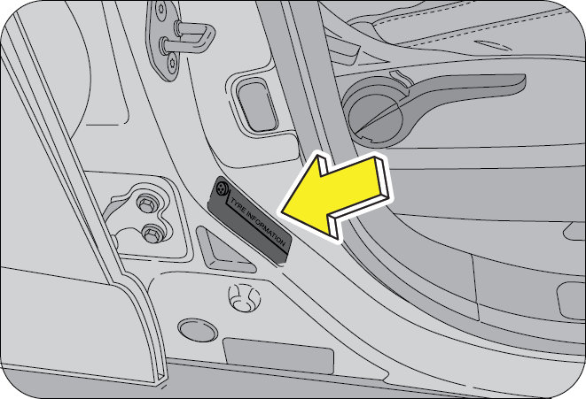
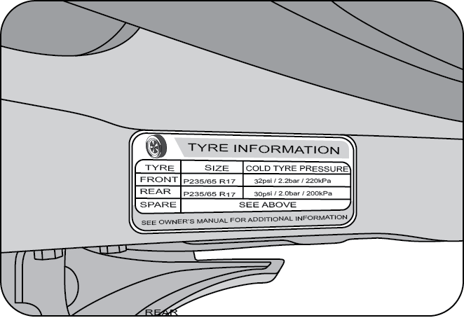
Tyre Label (Vehicle Placard) is located on the driver side inner B-pillar. This placard tells you important information about tyre size designed for your vehicle, and the tyre inflation pressures for the front & rear tyres.
| XUV500 COLD TYRE INFLATION PRESSURE bar/psi/kPa | |
|---|---|
| TYRE | P 235/65 R17 |
| FRONT | 2.2 / 32 / 220 |
| REAR | 2.0 / 30 / 200 |
Never overload your vehicle. Overloading can cause tyre failure, affect vehicle handling, and increase your stopping distance, resulting in an accident and/or serious personal injury.
Improper inflated tyres can adversely affect vehicle handling or can fail unexpectedly, resulting in an accident and/or serious personal injury.
13.4 Tyre Pressure
Proper tyre inflation pressure is essential to the safe and satisfactory operation of your vehicle. Three primary areas are affected by improper tyre pressure;
- Safety
- Economy
- Ride Comfort and Vehicle Stability
Proper tyre inflation contributes to a comfortable and safe ride. Overinflating produces a jarring and uncomfortable ride. Both underinflation and overinflation affect the stability of the vehicle and can produce a feeling of sluggish response or over responsiveness in the steering. Unequal tyre pressures can cause erratic and unpredictable steering response or may cause the vehicle to drift left or right.
Improper inflation pressures can cause uneven wear patterns to develop across the tyre tread. These abnormal wear patterns will reduce tread life resulting in a need for earlier tyre replacement. Underinflation also increases tyre rolling resistance and results in higher fuel consumption.
The proper cold tyre inflation pressure is listed in the Tyre Label (Vehicle Placard), located on the driver side inner B-pillar.
13.4.1 Inspection and Adjustment Procedure
The tyre pressure should be checked and adjusted, as well as inspected for signs of tyre wear or visible damage, at least once a month. Use a good quality pressure gauge to check tyre pressure. Do not make a visual judgement when determining proper inflation. Radial tyres may look properly inflated even when they are under-inflated. At the same time, each tyre should be inspected for signs of tyre wear or visible damage.
Inflation pressures specified on the placard are always cold tyre inflation pressures. Cold tyre inflation pressure is defined as the tyre pressure after the vehicle has not been driven for at least three hours, or driven less than 1 km after a three-hour period. Check tyre pressures more often if subject to a wide range of outdoor temperatures, as tyre pressures vary with temperature changes. Tyre pressures change by approximately 1 psi (7 kPa) per 7°C of air temperature change. Keep this in mind when checking tyre pressure inside a garage, especially in the winter.
When it was new, the spare tyre in your vehicle was fully inflated. However, a spare tyre can lose pressure over time. In order to avoid being stranded, check the spare tyre air pressure frequently.
13.4.2 Inflating Your Tyres
Safe operation of your vehicle requires that your tyres are properly inflated. Remember that a tyre can lose up to half of its air pressure without appearing flat.
At least once a month or before long trips, inspect each tyre and check the tyre pressure with a tyre gauge (including spare tyre). Inflate all tyres to the recommended inflation pressure.
You are strongly urged to buy a reliable tyre pressure gauge, as automatic service station gauges may be inaccurate. Mahindra recommends the use of a digital or dial-type tyre pressure gauge rather than a stick-type tyre pressure gauge.
Use the recommended cold inflation pressure for optimum tyre performance and wear. Under-inflation or over-inflation may cause uneven tread wear patterns.
Under-inflation is the most common cause of tyre failures and may result in severe tyre cracking, tread separation or “blowout”, with unexpected loss of vehicle control and increased risk of injury. Underinflation increases sidewall flexing and rolling resistance, resulting in heat buildup and internal damage to the tyre. It also may result in unnecessary tyre stress, irregular wear, loss of vehicle control and accidents.
Always inflate your tyres to the recommended pressure even if it is less than the maximum inflation pressure information found on the tyre. The recommended tyre inflation pressure is found on the Tyre Label which is located on the driver side inner B-pillar. Failure to follow the tyre pressure recommendations can cause uneven tread wear patterns and adversely affect the way your vehicle handles.
- Make sure the tyres are cool, meaning they are not hot from driving even a kilometer. If you are checking tyre pressure when the tyre is hot, (i.e. driven more than a km, never “bleed” or reduce air pressure. The tyres are hot from driving and it is normal for pressures to increase above recommended cold pressures. A hot tyre at or below recommended cold inflation pressure could be significantly under-inflated
- Remove the cap from the valve of the tyre, firmly press the tyre gauge onto the valve and measure the pressure
- Add enough air to reach the recommended air pressure
- Replace the valve cap
- Repeat this procedure for each tyre, including the spare
If you overfill the tyre, release air by pushing the metal stem in the centre of the valve. Then re-check the pressure with your tyre gauge.
After inspecting or adjusting the tyre pressure, always reinstall the valve stem cap (if equipped). This will prevent moisture and dirt from entering the valve stem, which could damage the stem, resulting in an unexpected loss of tyre pressure, an accident and/or serious personal injury.
13.4.3 Radial Ply Tyres
Combining radial ply tyres with other types of tyres on your vehicle will cause your vehicle to handle poorly, resulting in an accident and/or serious personal injury. Always use radial tyres in sets of four. Never combine them with other types of tyres.
13.4.4 Tread Wear Indicators (TWI)
Tread wear indicators are molded into the bottom of the tread grooves. They will appear as bands when the tread depth becomes 1/16 inch (2 mm). When the indicators appear in two or more adjacent grooves, the tyre should be replaced.
Avoid abrupt maneuvering and braking. This can cause tyre deterioration and lead to loss of steering or braking control.
13.4.5 Life of Tyre
The service life of a tyre is dependent upon various factors including but not limited to;
- Driving style
- Tyre pressure
- Distance driven
Tyres and the spare tyre should be replaced after six years, regardless of the remaining tread. Failure to follow this warning can result in sudden and unexpected tyre failure, leading to an accident and/or serious personal injury.
Keep dismounted tyres in a cool, dry place with as little exposure to light as possible. Protect tyres from contact with oil, grease and fuels.
Do not use a tyre, wheel size or speed rating other than that specified for your vehicle on the tyre placard. Combinations of unapproved tyres and wheels may change suspension geometric and performance characteristics, resulting in changes to steering, handling and braking of your vehicle. This can cause unpredictable handling, stress to steering and suspension components. You could lose control of the vehicle or the tyre can unexpectedly fail, resulting in an accident and/or serious personal injury.
Replacing original tyres with tyres of a different size may result in false speedometer and odometer readings.
13.5 Snow Chains
Snow chains of size D 125 S can be used on the front wheels
In case of harsh winter driving conditions, it is recommended using winter tyres with the same specifications for better stability, safety and performance.
13.6 Tyre Rotation Recommendations
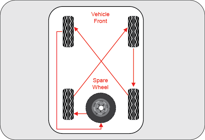
Tyres on the front and rear axles of vehicles operate at different loads and perform different steering, handling, and braking functions. For these reasons, they wear at unequal rates and develop irregular wear patterns.
Rotation will increase tread life, help to maintain mud, snow, and wet traction levels, and contribute to a smooth, quiet ride. Follow the recommended tyre rotation frequency for your type of driving.
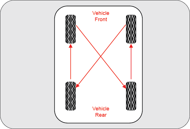
It is recommended rotating the tyres as per the "Maintenance Schedule".
The suggested rotation method is the "forward-cross" shown in the diagram. The benefits of rotation are especially worthwhile with aggressive tread designs such as those on On/Off-road type tyres.
Rotation will increase tread life, help to maintain mud, snow, and wet traction levels, and contribute to a smooth, quiet ride. Follow the recommended tyre rotation frequency for your type of driving. More frequent rotation is permissible if
desired. The reasons for any rapid or unusual wear should be corrected prior to rotation being performed.
If you have rotated, repaired, changed your tires or changed the wheel rims, check the wheel nuts are still tight (to the specified torque) after driving about 1000 Kms.
13.7 Changing a Flat Tyre
Refer to “If you have a Flat Tyre” section in the General chapter for details.
13.7.1 Wheel Tightness
When you change a wheel, remove all rust and dirt at all locations where the wheel contacts the wheel hub. Use a scraper or wire brush to be sure that you remove all rust and dirt.
Always tighten the nuts in a crisscross sequence. Never use oil or grease on your wheel studs or nuts.
Never over tighten the nuts on the wheel stud. You could damage the stud or the nut.
Recheck the nut tightness after the first 100 kms. of driving.
A loose wheel could have damaged or elongated the holes in the rim, or damaged the rim/hub assembly. If any of the wheel studs or nuts are damaged, contact the nearest Authorized Mahindra Dealer.
13.8 Tyre Pressure Monitoring System (TPMS) (if equipped)
TPMS is an electronic system designed to monitor the air pressure inside the pneumatic tyres. This system will alert the driver if the tyre pressure falls below the low pressure warning limit for any reason, including low temperature effects and natural pressure loss through the tyre.
The TPMS will continue to alert the driver and will not turn off until the tyre pressure is inflated to the recommended pressure.
TPMS uses wireless technology with wheel rim mounted electronic sensors to monitor tyre pressure levels. Sensors mounted to the valve stem of each wheel, transmit tyre pressure readings to the receiver module. Receiver module in turn will communicate this information to the instrument cluster and infotainment system. Tyre locations will display as OK, if all tyre pressure and temperature are in the recommended range.
The TPMS has been customized only for the manufacturer’s genuine tyres and wheels. TPMS pressure limits and warning messages have been established for the tyre size equipped on your vehicle.
Replacement of manufacturer’s parts with a different size, type or style of components may damage the sensor and lead to incorrect readings.
Do not use aftermarket tyre sealants or balance beads if your vehicle is equipped with TPMS. Failure to comply may lead to sensor damage.
The TPMS is not intended to replace normal tyre care and maintenance or to provide warning of a tyre failure or condition.
The TPMS should not be used as a tyre pressure gauge while adjusting vehicle tyre pressure.
Driving with under-inflated tyres cause the tyres to overheat and may lead to tyre failure.
Under-inflated tyres reduce fuel efficiency, tyre tread life and may affect the vehicle's maneuverability & braking ability.
The TPMS is not a substitute for tyre maintenance, it is the driver's responsibility to maintain correct tyre pressure using an accurate pressure gauge, even if under-inflation has not reached the level to trigger illumination of the TPMS warning indicator.
13.8.2 TPMS Warning Lamp
- Sensor signal missing
- Sensor faulty
- Low pressure (< 24 psi / 1.65 bar )
- High pressure (> 48 psi / 3.31 bar)
- Air leakage (> 3 psi/sec / 0.25 bar/sec)
- High temperature (>980 C)
The error is also displayed on the infotainment screen as below. If above condition occurs, contact the nearest Authorized Mahindra Dealer for further assistance.
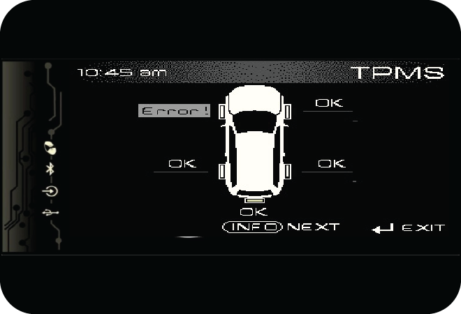
Examples of TPMS warning lamp illumination and corresponding infotainment screen display;
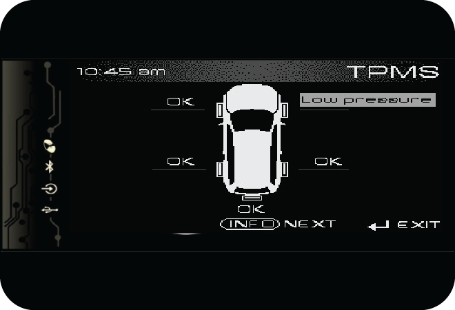
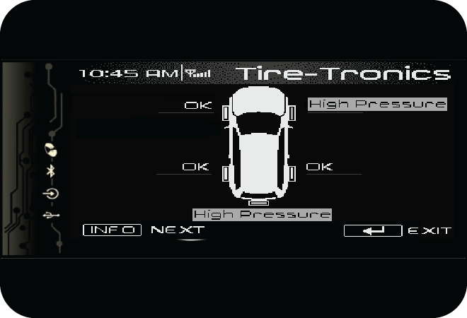
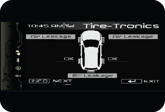
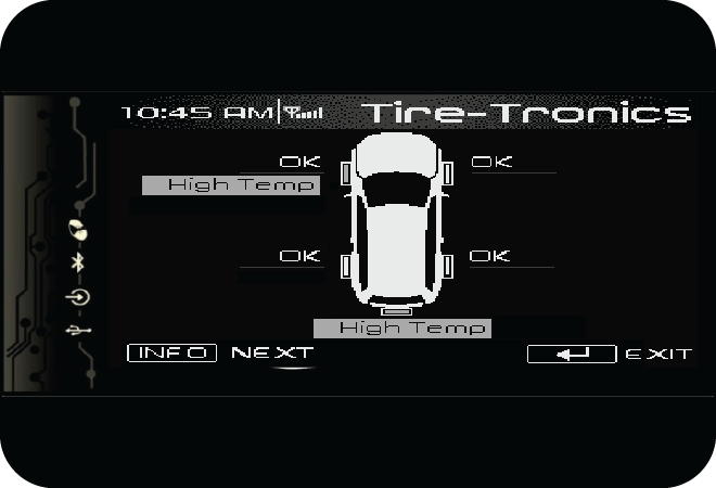
13.8.3 TPMS Learning
After a tyre rotation or TPMS sensor replacement, the receiver must be learnt, else the TPMS warning lamp indicates a malfunction.
TPMS learning button (A) is located to the left hand side of the instrument cluster.
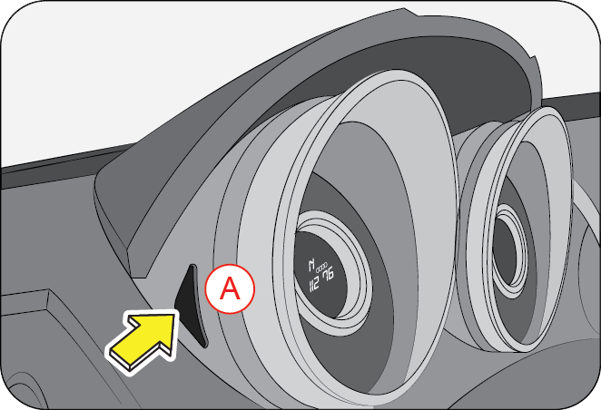
13.8.4 TPMS Learning Procedure
- Press the TPMS button in the cluster and turn ignition ON along with the button pressed. The infotainment screen displays as below and TPMS warning lamp in the cluster starts blinking.
- Start removing air from front left tyre, once the tyre gets learnt, vehicle alarm and hazard lamps flash once. The infotainment screen display is as below.
- Repeat the above step for front right tyre, rear right tyre and rear left tyre (in the same order). Corresponding infotainment screen displays are as below.
- Start removing air from spare tyre. Once the tyre gets learnt, vehicle alarm and hazard lamps flash 3 times to indicate all the tyres were learnt. The infotainment screen display is as below indicating all tyres were learnt successfully.
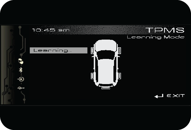
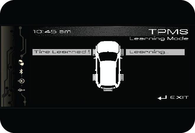
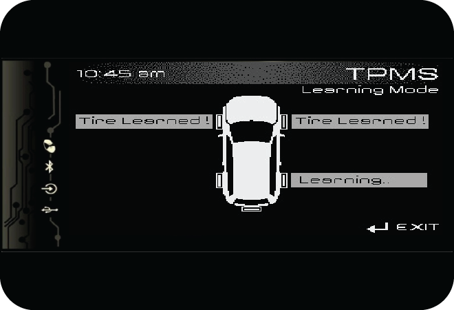
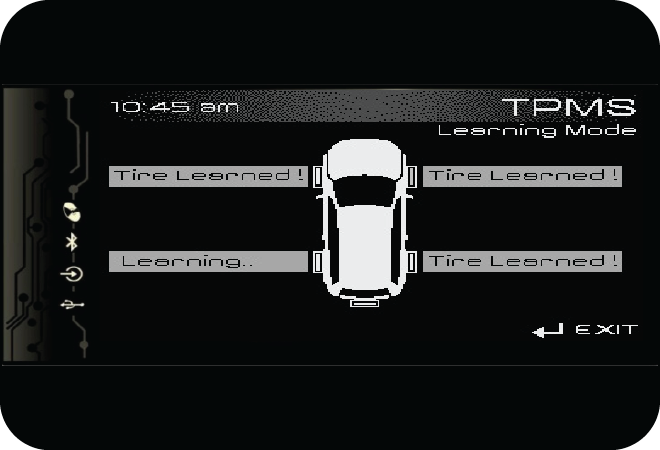
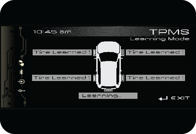
If there were any problem in learning, the alarm and hazard lamps flash 5 times to indicate the tyre learning was not complete.
13.8.5 Tyre Swap
If a tyre was swapped with the spare tyre, system alerts the user through infotainment as below;
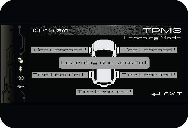
Press the TPMS button in the cluster to acknowledge the same. TPMS warning lamp will continue to glow if the spare tyre is having any pressure or temperature alert. After correction, press the TPMS button to acknowledge the spare tyre has been corrected and to remove the alert in the cluster/infotainment.
Please note, if swapping is done for more than one tyre or with the other running tyres, system cannot identify the same and the system needs to be relearned.
14 EMERGENCIES
14.1 Hazard Warning Flashers
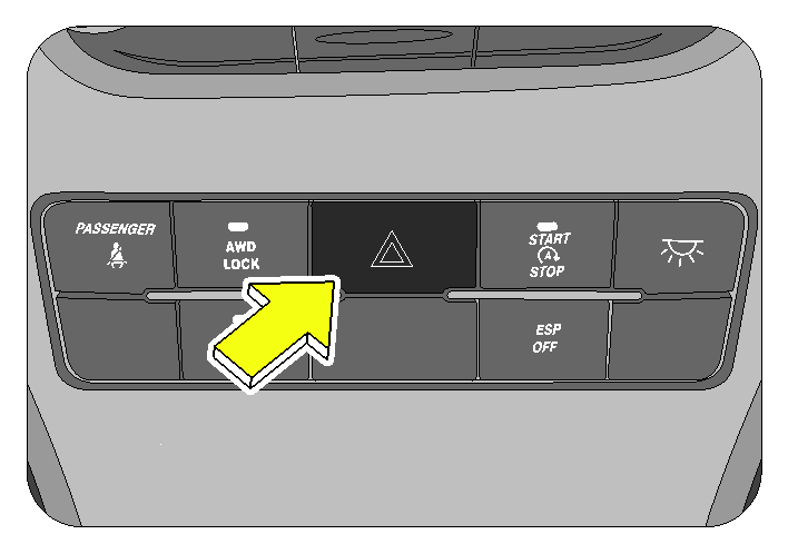
The hazard warning flasher button is located in the central bezel switch bank. Press the button to turn ON the hazard warning flashers, all directional turn signals will flash to warn oncoming traffic. This is an emergency warning system and should be used only when there is an emergency. Use it when your vehicle is disabled and is a safety hazard for other motorists. Hazard warning flasher will work in all positions of the ignition key and even when the vehicle is fully locked.
With extended use, the hazard warning flasher may drain your vehicle battery.
14.2 Vehicle does not Start - Checks
Before making these checks, make sure you have followed the correct starting procedure and that you have sufficient fuel.
- Check that the battery terminals are tight and clean
- If the battery terminals are firmly fastened, turn the interior lamps ON
- If the lamps do not illuminate, glow dim or go OFF when the starter is cranked, the battery is weak or discharged. Try jump starting. Follow “Jump starting” instructions given later in this chapter
- If the lamp illumination is normal, engine cranking normally, but the engine does not start even after repeated cranking, it needs adjustment or repair. Contact an Authorized Mahindra Dealer.
- During winter, use of non-winter diesel or due to extreme cold conditions, the vehicle may not start. Contact an Authorized Mahindra Dealer for further assistance.
To prevent damage to the starter, do not crank the engine for more than 15 seconds at a time. Wait 10 to 15 seconds before trying again.
Reduce your speed gradually, keeping a straight line. Move cautiously off the road to a safe place. Turn ON your hazard warning flashers and check for any malfunction lamps in the instrument cluster. Turn the ignition OFF, wait for approximately 90 sec and try starting the engine again. If the vehicle still does not start contact an Authorized Mahindra Dealer.
If the engine stalls while running, the power assist for the brakes and steering will not work, steering and braking will be much harder than usual.
If engine speed does not increase when the accelerator pedal is depressed, there may be a problem in the Engine Management System, electrical or electronic controls. In case of certain faults, the engine may go to limp home mode, which is indicated by the check engine lamp. Have your vehicle checked by an Authorized Mahindra Dealer as soon as possible.
14.3 Vehicle Overheating
If the LED’s of the temperature gauge in the instrument cluster is all the way up to the H and/or the high engine coolant temperature warning lamp is ON, your engine has overheated.
Upon engine getting overheated, the Engine Management System reduces engine power substantially and may even shut the engine OFF; it is dangerous to continue driving when the engine has overheated. You need to first cool the engine down before starting to drive again.
Follow the below instructions to cool the engine down
- Progressively reduce the vehicle speed and bring vehicle to a stop at the side of the road
- Turn ON the hazard warning flashers
- Keep the engine running at idle
- Engage the parking brake
- Switch the air conditioner OFF
- You can keep the AC blower speed at maximum and set the temperature control knob to the extreme end of he hot zone (clockwise end)
- Wait till the engine coolant temperature drops sufficiently such that the LED’s in the temperature gauge is around halfway between C & H
Now switch the engine OFF and carefully open the bonnet/hood to visibly inspect the engine cooling system parts. Be cautious while doing an inspection as vehicle parts will still be too hot. Verify that the engine coolant level in the coolant recovery tank is maintained between 'Min' and 'Max' mark. Check for possible fluid leakages. Check for damages to heat exchangers and connecting hoses. Also verify that the radiator shrouds and engine fan blades, engine belt all are in good condition.
If any evidence of failure is observed, contact the nearest Authorized Mahindra Dealer for help. In case, no system leakage/failure is suspected, driving can be continued.
Either due to severe operating conditions or due to any system leakages or failures, the engine can get overheated. However if the engine is getting overheated repeatedly, even in normal operating conditions, get the vehicle checked by a Authorized Mahindra Dealer as soon as possible.
Refer to the 'High Engine Coolant Temperature' section under the 'Features and Control' chapter for details.
If the high engine coolant temperature warning is ignored, the engine shuts OFF abruptly to safeguard engine components from overheating and consequent failure. Abrupt engine shut-off can lead to uncontrollable driving condition and accidents.
Stay clear of hot and rotating vehicle parts while visually inspecting the vehicle. The coolant inside the cooling system is under high pressure and temperature. Never open the pressure cap of the radiator when the engine is hot. Not taking precautions may lead to serious injury to your skin/eyes.
For optimum performance of the cooling system you must maintain the required coolant level and use only recommended engine coolant.
14.4 Jump Starting
If your vehicle's battery has run down, you may be able to start the engine by using a standalone booster battery or a vehicle with a good condition battery.
But before going ahead with this procedure ensure that battery is the cause of vehicle not starting. To confirm this, few simple tests can be conducted as follows;
- Check the headlights - Are they dim or bright? If they are dim, it's likely your battery is dead. If your headlights are bright, you do not have a dead battery and a jump start may not help.
- Try to start the car -Does it turn over very slowly, or does it crank quickly? If it cranks quickly, you do not have a dead battery and a jump start may not help. If it cranks slowly, or not at all, you probably have a dead battery.
- The positive terminal will be marked with a plus sign (+) and will usually have a RED cable attached on it.
- The negative terminal will be marked with a minus sign (-) and will usually have a BLACKcable attached to it.
-
Park the working car near the disabled car. Park the car in such a way that the distance between both car batteries is as small as practical. Turn off the engine, radio, lights, A/C, fans and all other electrical components. Make sure that all of these things are OFF in the disabled car, too.
Don't let the cars touch each other.
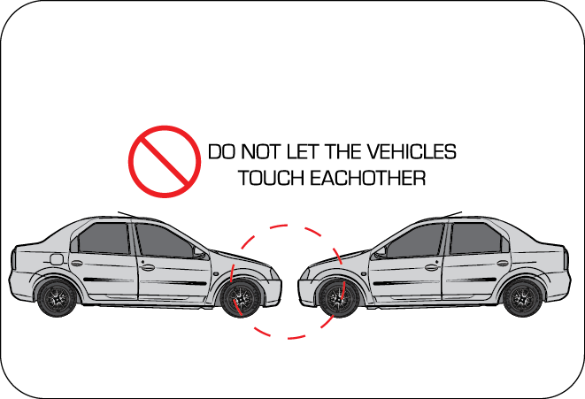
-
Wear safety gear (goggles or face guard and gloves) if you have it.
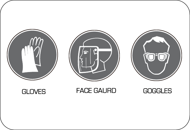
-
Untangle and unwind your jumper cables. Like your batteries, your jumper cables will probably have red and black cables and will have heavy duty clamps to connect to the battery terminals. You must make sure that the red and black ends of your jumper cables never touch each other once they are connected to the batteries; permitting them to do so can result in serious arcing and/or damage to one or both vehicles
-
Connect the jumper cables in the order described below;
- Connect one red clamp to the positive (+) terminal of the dead battery/disabled vehicle
- Connect the other red clamp to the positive (+) terminal of the good battery
- Connect one black clamp to the negative (-) terminal of the good battery
- Connect the other black clamp to a piece of grounded metal on the dead vehicle, preferably shiny metal (not painted or oily) that is attached to the engine. Usually a nut, bolt or other protruding shiny metal will work. You may see a small spark when you connect to a good ground. As a last resort, you may connect to the negative (-) post of the dead battery, but this risks igniting hydrogen gas coming off the battery
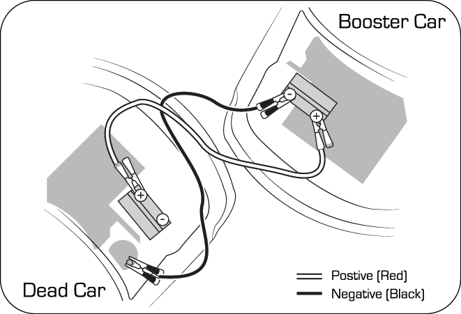
Make sure none of the cables are dangling into the engine compartment, where they could be exposed to moving parts.
- Start the working car. Let it idle for a few minutes. Rev the engine a little above idle for 30 to 60 seconds. You do this to charge the battery in the dead car. A good clean connection between the battery cables and the battery terminals is essential.
- Try to start the disabled vehicle. If it does not start, shut the engine off and disconnect the last connection temporarily while you slightly twist or wiggle each of the four clamps to help ensure a good electrical connection. Restart the working car again. Allow another 5 minutes for charging before attempting to start the disabled vehicle. If this does not work after a few tries, you may need to have the car towed or the battery replaced.
-
Remove the jumper cables once the car starts. Do this in the reverse of the order in which they were attached, and don't let any of the cables or clamps touch each other (or dangle into the engine compartment).
- Disconnect the black clamp from grounded metal on the dead car.
- Disconnect the black clamp from the negative (-) terminal of the good battery.
- Disconnect the red clamp from the positive (+) terminal of the good battery.
- Disconnect the red clamp from the positive (+) terminal of the dead battery
Replace any positive (+) red post protective covers if applicable (You have had to remove or open these in the beginning) These covers help prevent accidental short circuiting the battery.
-
Keep the recently-disabled car's engine running. Run the car above idle (slightly revved up with your foot on the accelerator). This should give the battery enough charge to start the car again. If it does not, you probably have a dead battery or a dying alternator.
Improper jump starting procedure can result in battery explosion and acid burn hazard.
Loosely connected battery cables could damage the electronic control units.
To disconnect battery terminals wait for at least 2 minutes to allow discharge of high voltage or it could lead to personal injury.
While disconnecting, always disconnect the -VE terminal first and while connecting, always connect the -VE terminal last.
Open the bonnet and locate the battery (near the left side fender). Identify the positive and negative terminals.
Check the physical condition of the battery. Inspect batteries for cracks, leaks or other damage. If you find any of these things, do not jump start the car. Call Mahindra Road Side Assistance or replace the battery. If the weather is very cold, remove the refill caps and check the condition of the electrolyte. If it seems slushy or like ice, do not attempt jump-starting until it thaws.
14.5 Limp Home Mode
Limp home mode is an emergency situation declared by the EMS due to failure of one/more critical sensors/actuators. In this mode, the EMS will revert back to basic minimum requirement (fuel quantity / injection timings) to aid the driver to bring the vehicle back to the nearest workshop. Needless to say the drivability & fuel consumption will be greatly affected.
If vehicle acceleration worsens or if there is a drop in vehicle performance, there might be a malfunction in the engine management system which triggers/activates the Limp Home Mode.
Limp home mode is accompanied by the check engine lamp illuminating in the instrument cluster. In this mode, the vehicle speed is limited and the accelerator pedal may not function normally. It is recommended you contact an Authorized Mahindra Dealer immediately for assistance.
The limp home mode can be erased, only after rectifying the problem
14.6 Towing
Your vehicle comes with a front welded tow hook and a rear towing eyelet where a tow hook can be screwed in. The front tow hook should be used when the vehicle needs towing, and the rear tow hook should be used when your vehicle is utilized for towing other vehicles.
If your vehicle needs to be towed, call a professional towing service. If a towing service is unavailable in an emergency, your vehicle may be temporarily towed by a towing cable or chain secured to the emergency towing hook welded into the front cradle assembly of the vehicle.
The tow eye is in the tools pouch in the jack storage compartment at the rear of the vehicle.
Remove/price out the tow hook cover in the rear bumper using a screwdriver. Screw in the tow eye in the counter clockwise direction (tow eye is LH threaded) and tighten. Fasten a cable or chain specifically intended for use in towing vehicles to the towing hook.
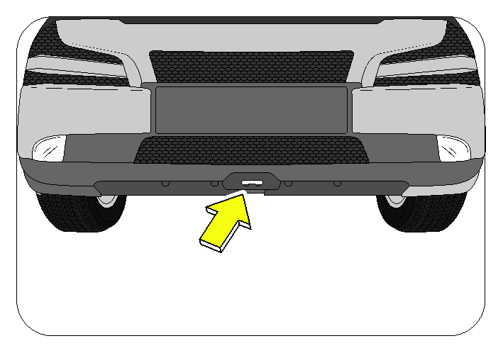
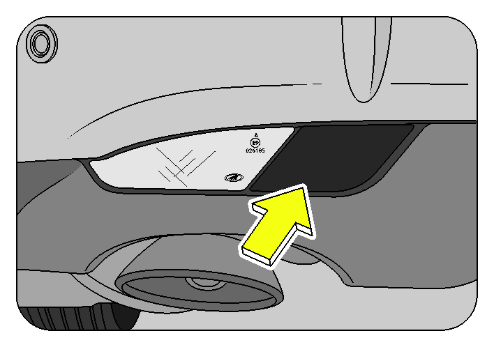
14.6.1 Towing Equipment
| Towing Options | Variant | |
|---|---|---|
| 2WD | AWD | |
| Front towing hook | ü | ü |
| Rear towing eyelet | ü | ü |
| Flatbed towing | ü | ü |
| Towing by all 4 wheels | ü | ü |
| Sling type towing (front wheel lift) | ü | |
| Sling type towing (rear wheel lift) | ü | ü |
- Flat-bed equipment - Your vehicle is loaded on the back of a truck. This is the safest and best way of towing.
- Sling-type equipment - The tow truck uses metal cables with hooks on both ends. These hooks go around parts of the frame or suspension and lift the end of the vehicle off the ground. This is not a good method of towing as it may damage the vehicle's suspension and body. Avoid a tow with sling type equipment
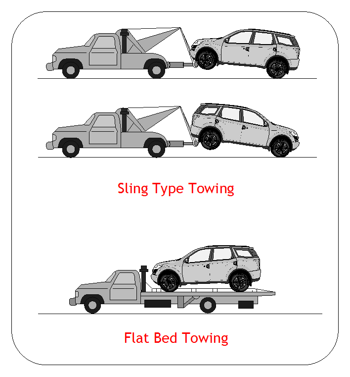
15 MAINTENANCE
15.1 General Owners Information
Your vehicle has been designed for fewer maintenance requirements with longer service intervals to save both your time and money. However, each regular maintenance, as well as day-to-day care is more important to ensure a smooth, trouble free, safe and economical operation.
The service reminder alert comes up on the infotainment screen when your vehicle needs to be serviced. Take your vehicle to the nearest Authorized Mahindra Dealer for service
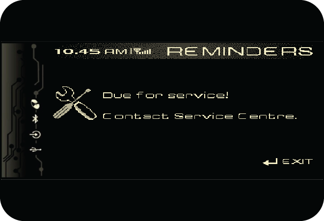
It is the owner's responsibility to make sure the specified maintenance, including general maintenance service is performed. Note that both the new vehicle limited warranty and emission control system limited warranties specify that proper maintenance and care must be performed. See Service Coupon Booklet for complete warranty information.
Mahindra technicians are well trained specialists and are kept up to date with the latest service information through technical bulletins, service tips, and in dealership training programs. They learn to work on Mahindra vehicles before they work on your vehicle, rather than while they are working on it.
You can be confident that your Mahindra dealer's service department does the best job to meet the maintenance requirements on your vehicle reliably and economically.
Routine maintenance is the best way to help ensure you get the performance, dependability, long life and better resale value you expect from your vehicle. This is exactly why we've put together this Maintenance Section. It outlines the services required to properly maintain your vehicle and when they should be performed. The focus is on maintaining your vehicle while it's running great, which goes a long way toward preventing major repairs and expenses later.
Here are a few suggestions to help you get started on routine maintenance:
- Familiarize yourself with your vehicle by going through your Owner's Manual
- Take a few minutes to review this Maintenance Section
- Make it a habit to use this manual to record scheduled maintenance in the Service Coupon Booklet
- Consult your Authorized Mahindra Dealer for all your vehicle's needs.
15.2 General Owners Information
Your vehicle has been designed for fewer maintenance requirements with longer service intervals to save both your time and money. However, each regular maintenance, as well as day-to-day care is more important to ensure a smooth, trouble free, safe and economical operation.
It is the owner's responsibility to make sure the specified maintenance, including general maintenance service is performed. Note that both the new vehicle limited warranty and emission control system limited warranties specify that proper maintenance and care must be performed. See Warranty Information & Maintenance Guide for complete warranty information.
Mahindra technicians are well trained specialists and are kept up to date with the latest service information through technical bulletins, service tips, and in dealership training programs. They learn to work on Mahindra vehicles before they work on your vehicle, rather than while they are working on it.
You can be confident that your Mahindra dealer's service department does the best job to meet the maintenance requirements on your vehicle reliably and economically.
Routine maintenance is the best way to help ensure you get the performance, dependability, long life and better resale value you expect from your vehicle. This is exactly why we've put together this Maintenance Section. It outlines the services required to properly maintain your vehicle and when they should be performed. The focus is on maintaining your vehicle while it's running great, which goes a long way toward preventing major repairs and expenses later.
Here are a few suggestions to help you get started on routine maintenance:
- Familiarize yourself with your vehicle by going through your Owner's Manual.
- Take a few minutes to review this Maintenance Section.
- Make it a habit to use this manual to record scheduled maintenance in the Service Coupon Booklet.
- Consult your Authorized Mahindra Dealer for all your vehicle's needs.
15.3 Suggestions for Obtaining Service for your Vehicle
If you have warranty work to be done, be sure to have the right papers with you. All work to be performed may not be covered by the warranty. Discuss additional charges with the service manager. Keep a maintenance log of your vehicle's service history.
Make a written list of your vehicle's problems or the specific work you want done. If you've had an accident or work done that is not on your maintenance log, let the service advisor know about it.
If you list a number of items and you must have your vehicle by the end of the day, discuss the situation with the service advisor and list the items in order of priority.
15.4 Need Assistance?
Mahindra and its authorized dealers are vitally interested in your satisfaction. We want you to be content with our products and services. The warranty service must be done by an Authorized Mahindra Dealer. We strongly recommend that you take the vehicle to an Authorized Mahindra Dealer even for regular service or repairs. They know the vehicle best, and are most concerned that you get prompt and high quality service. All Authorized Mahindra dealers have the facilities, factory trained technicians, special tools and the latest information to ensure the vehicle is fixed correctly and in a timely manner.
It is recommended talking to an Authorized Mahindra Dealer service manager first. Most matters can be resolved with this process. If for some reason you are still not satisfied, talk to the general manager or owner of the dealership.
If an Authorized Mahindra Dealership is unable to resolve the concern, you may contact Mahindra Customer Care executives. They would need the following information:
Owner's name and address, Owner's telephone number (home and office), Authorized Dealership name, Vehicle Identification Number (VIN), vehicle delivery date and mileage.
15.5 Warranty Information
See the Warranty Guide in the Service Coupon Booklet for the terms and provisions of Mahindra warranties applicable to this vehicle. Mahindra Genuine parts fluids, lubricants, and accessories are available at any Authorized Mahindra Dealer. They will help keep the vehicle operating at its best.
15.5.1 Protect your Warranty
Routine maintenance is not only the best way to help keep your vehicle performing as intended, it's also the best way to protect your warranty. Failure to perform scheduled maintenance specified in the Warranty Information & Maintenance Guide will invalidate warranty coverage on parts affected by the lack of maintenance. We can't stress enough how important it is to keep records of all maintenance. Damage or failures due to neglect or lack of proper maintenance are not covered under warranty.
15.6 Maintenance Record
It's important to document the maintenance of your vehicle. For your convenience to maintain records of service, ecoupons are provided in the Warranty Information & Maintenance Guide. Every time you bring your vehicle in for scheduled maintenance, be sure to present this guide and certify the work. Also record the date of service, mileage at the time of service. This will make record keeping easy and, should your vehicle ever require warranty coverage, you will have all the documentation to show you've properly maintained it.
15.7 Maintenance Interval
Mahindra establishes recommended maintenance intervals based upon engineering testing to determine the most appropriate mileage to perform the various maintenance services. This protects your vehicle at the lowest overall cost to you. Mahindra recommends that you do not deviate from the maintenance schedules presented in this Maintenance Schedule.
15.8 Vehicle Self Maintenance - General Precautions
- Refer relevant sections of the manual before starting
- Set the parking brake
- Block the wheels to prevent the vehicle from moving unexpectedly
- Turn OFF the engine and remove the key
- Stay clear of hot vehicle parts
- Avoid repeated contact with fluids
- Do not let fuel, coolant and other fluids spill over electrical and hot vehicle parts
- Keep all open flames and other burning material like cigarettes away from the battery and all fuel related parts
Do not start/run the engine when any engine/peripheral parts are removed.
15.9 Opening the Hood
The hood release lever is located in the driver side foot well area, below the instrument panel. To open the hood, follow the steps below;
- Pull the lever below the driver side IP to release the hood
- Lift the hood a little to access the safety latch holding the hood striker. This safety latch is located below the hood at the centre
- Lift the safety latch and lift the hood
- Release the unhinged end of the stay rod from its lock clip, swing the rod upwards and insert its unhinged end in the slot below the already lifted hood
- Allow the hood to be supported by the stay rod
- Do not apply any undue force on the bonnet when it is supported by the stay rod
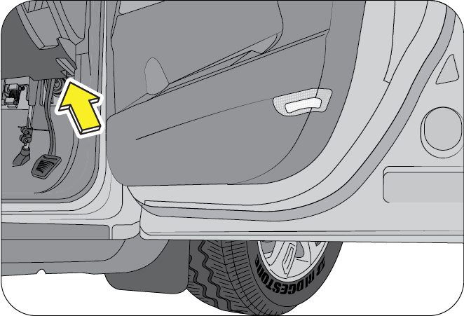
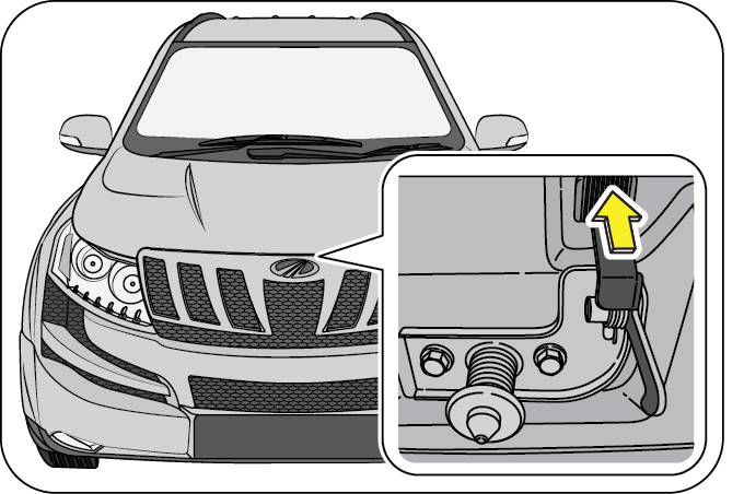
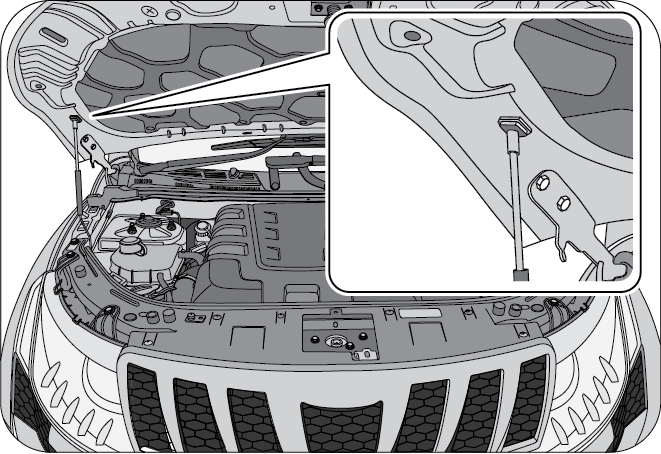
- Do not open the hood immediately after a drive; the engine compartment will be very hot.
- Always double check to be sure that the hood is firmly latched before driving away. If it is not latched properly, the hood could open while the vehicle is being driven, causing a total loss of visibility, resulting in an accident.
- Do not move the vehicle with the hood in the raised position, as vision is obstructed.
15.10 Closing the Hood
- Remove the stay rod supporting the hood by slightly lifting the hood
- Slowly lower the hood, while swinging down the stay rod and locking its unhinged end in the lock clip
- Bring the hood just a few inches above its fully closed position
- Now, release the hood and allow it to fall by its own weight. This ensures that safety latch firmly locks the hood in its fully closed position
15.11 Engine Compartment
| A | Degassing Tank | G | Dipstick |
| B | Power Steering Fluid Reservoir | H | Fuel Priming Pump |
| C | Front Windshield Washer Fluid Reservoir | I | Air Filter Assembly |
| D | Engine Oil Cap | J | Battery |
| E | Brake/Clutch Fluid Reservoir | K | Engine Compartment Fuse Box |
| F | Engine Cover |
Maintenance is classified as below;
- General Maintenance
- Scheduled Maintenance
15.12 General Maintenance
Exercise extreme caution when the hood is open and engine is ON.
Listed below are the general maintenance items that should be performed frequently. In addition to checking the items listed below, if you notice any unusual noise, fluid leakages, smell or vibration, you should investigate the cause or take your vehicle to your Authorized Mahindra Dealer or a qualified service shop immediately.
Make these checks only with adequate ventilation if you intend to run the engine.
- Front windshield washer fluid level
- Engine coolant level
- Battery condition
- Brake/Clutch fluid level
- Engine oil level
- Power steering fluid level
- Fluid leaks
- Hoses, joints and pipes for any abnormalities
- Lights
- Warning lamps
- Windshield wipe and wash
- Steering wheel
- Seats
- Seat belts
- Accelerator pedal
- Brake pedal
- Brakes
- Parking brake
- Gear lever shift mechanism
- Lamps
- Fluid leaks
- Doors and engine hood latches
- Tyre inflation pressure
- Tyre surface/thread and wheel nuts
15.13 In the Engine Compartment
Check the engine compartment and the underbody of the vehicle for any leaks. If you smell fuel vapor or notice any leak, have the cause found and corrected immediately.
Engine oil has the primary functions of lubricating and cooling the inside of the engine. It plays a major role in maintaining the engine in proper working order. Therefore, it is essential to check the engine oil regularly.
It is normal for engines to consume some engine oil during operation.
Causes of consumption in a normal engine are as follows;
- Oil is used to lubricate pistons, piston rings and cylinders. Thin films of oil, left over when pistons move in cylinders, are sucked into the combustion chamber due to high negative pressure generated when the vehicle is decelerating. This oil gets burnt in the combustion chamber.
- Oil is also used to lubricate the stems of intake valves. Some of this oil is sucked into the combustion chamber together with the intake air and is burnt there.
- Engine oil consumption depends upon the viscosity and quality of the oil, and upon the conditions in which the vehicle is driven. Oil consumption will be more due to high speed driving and frequent acceleration and deceleration. A new engine may consume more oil since its pistons, piston rings and cylinder walls are not conditioned.
- Make sure the vehicle is on level ground
- Turn the engine OFF and wait a few minutes for the oil to settle down into the oil sump
- Apply the parking brake
- Open the hood, use stay rod to support the hood. Protect yourself from engine heat
- Locate and carefully remove the engine oil level dipstick
- Wipe the dipstick with a clean cloth. Insert the dipstick fully, then remove it again
- If the oil level is between “Min” and “Max” marks, the oil level is acceptable. DO NOT ADD OIL
- If the oil level is below the Min mark, add enough oil through the oil filler cap to raise the level within the “Min” and “Max” marks. Wait for few minutes after every top up for the oil to settle down before checking the level.
- Oil levels above the “Max” mark may cause engine damage/poor performance.
- Put the dipstick and the oil filler cap back and ensure it is fully/properly seated.
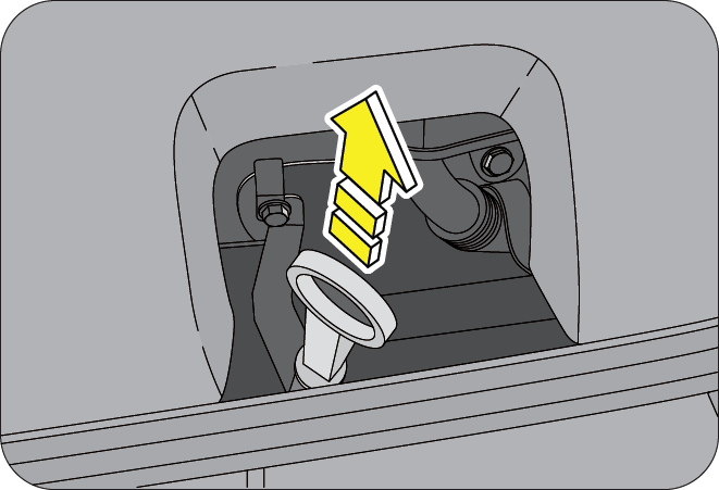
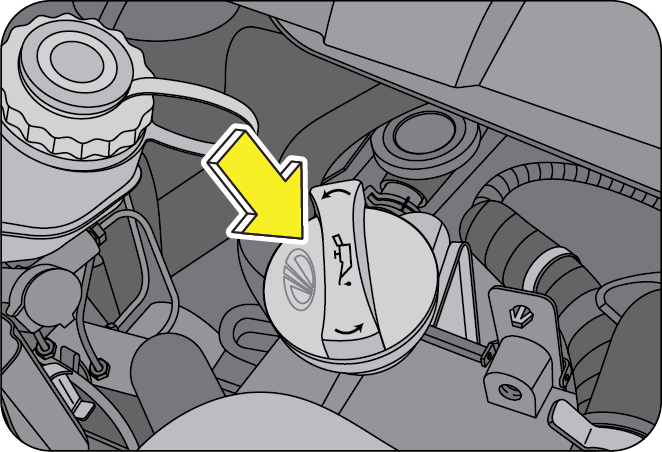
To avoid possible oil loss and injury due to hot blow-by gas, DO NOT operate the vehicle with the engine oil level dipstick and/or the engine oil filler cap removed.
Draining/Changing of engine oil should always be done by an Authorized Mahindra Dealer.
15.13.5 Checking/Topping Engine Coolant Level
- Park the vehicle on flat-horizontal surface. Keep the parking brake fully engaged. Shut-off the engine
- Wait till the engine cools down and hence coolant temperature comes down to normal room temperature
- The coolant level should be between “MIN” and “MAX” marking provided on the degassing tank
- In case the coolant level is below the “MIN” marking, the coolant should be topped-up
- The coolant should be filled till the level rises above the 'MIN' but remain below the “MAX” marking on the degassing tank
- However if the degassing Tank is found to be near empty, it is recommended that the system be checked at an Authorized Mahindra Dealer
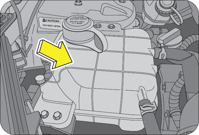
Never open the pressure cap when the engine is hot. Hot coolant may splash resulting in serious personal injury or severe burns by the erupting liquid.
Top up only with recommended Ready To Use (RTU) coolants for ensuring performance, anti-freezing and corrosion protection. Do not add water directly. Mixing with other brand of coolants is not recommended and should be avoided.
Draining or changing of engine coolant should always be done by an Authorized Mahindra Dealer.
15.13.6 Checking/Topping Brake/Clutch Fluid
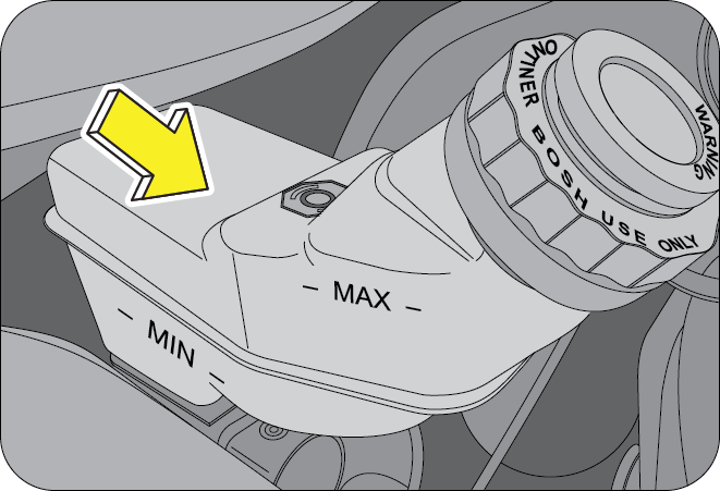
The brake and clutch systems are supplied fluid from the same reservoir.
The brake fluid level will drop slowly as the brakes wear, and will rise when the brake components are replaced. Fluid levels between the “MIN” and “MAX” lines are within the normal operating range; there is no need to add fluid. If the fluid levels are below the “MIN” mark, the performance of the systems could be compromised; the brake/clutch operation could be spongy and gear change harder. Top-up the recommended brake/clutch fluid till the “MAX” mark or contact an Authorized Mahindra Dealer immediately.
Carefully clean the cap on the reservoir before you remove it and be sure no debris fall in the reservoir. Do not keep the reservoir open for longer than necessary to add brake fluid.
Use only brake/clutch fluid that meets Mahindra specifications. Refer to ‘Lubricant and Capacities’ section.
Draining or changing of brake fluid should always be done by an Authorized Mahindra Dealer.
15.13.7 Checking/Topping Power Steering Fluid
Check the power steering fluid level at the defined service intervals. Refer to Maintenance Chart for details.
The fluid level should be checked if a leak is suspected, abnormal noises are apparent, and/or the system is not functioning as anticipated. Coordinate inspection efforts through an Authorized Mahindra Dealer.
Driving vehicle with power steering fluid below minimum mark will damage steering system.
Use only recommended power steering fluid. Do not use other types of power steering fluids which may damage the power steering system.
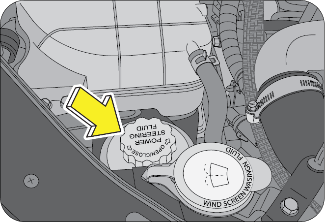
Fluid level in the reservoir should be checked on a level surface with the engine OFF to prevent injury from moving parts and to ensure accurate fluid level reading.
Follow the below steps for checking and topping up the power steering fluid;
- Start the engine and let it run until it reaches normal the operating temperature
- While the engine idles, turn the steering wheel left and right a couple of times
- Turn the engine OFF
- Check the power steering fluid level in the reservoir
- The fluid level should be maintained between the “MIN” and “MAX” marks
- If the fluid is low, add fluid in small amounts, continuously checking the level until it reaches the correct operating range. Be sure to put the cap back on the reservoir
- With a clean cloth, wipe any spilled fluid from all surfaces
Changing of power steering fluid should always be done by an Authorized Mahindra Dealer.
15.13.8 Windshield Washer Fluid Top-up
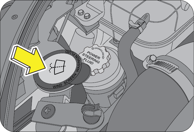
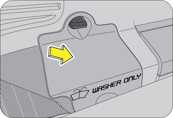
Top up both the front and rear (if equipped) windshield washer reservoirs as and when required.
The front windshield washer is located next to the power steering fluid reservoir in the engine bay. The rear windshield washer is located in rear luggage area LH trim behind the third row seats.
In very cold weather conditions, fill the reservoir with washer fluid premixed with anti-freeze.
If you operate your vehicle in temperatures below 4.5ºC, use washer fluid with anti-freeze protection. Failure to use washer fluid with anti-freeze protection in cold weather could result in impaired windshield vision and increase the risk of injury or accident.
15.13.9 Fuel Filter Bleeding/Priming
When the fuel level in the fuel tank falls very low, air may enter the fuel lines which leads to the engine not starting or abrupt switching OFF.
The air has to be removed from the fuel pump by priming the fuel pump. The fuel pump is located next to the air filter in the engine bay. Pump the fuel filter repeatedly using your palm and try starting the engine. If it fails, pump few more times and retry. If the engine still does not start, contact your nearest authorized Mahindra dealer for assistance.
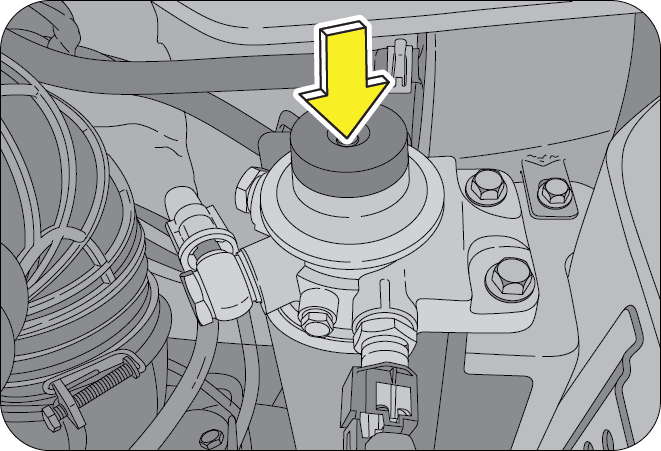
15.14 Maintenance - Inside the Vehicle
- Check all warning lamps appearing in the instrument cluster and DDAS. Refer to the relevant sections in this manual for further details.
- Check that all seat controls such as seat adjusters, seat back recliner, etc. operate smoothly and that all latches lock securely in any position. Check that the head restraints move up and down smoothly and that the locks hold securely in any latched position.
- Check that the seat belt system such as buckles, retractors and anchors operate properly and smoothly. Make sure the belt webbing is not cut, frayed, worn or damaged.
- Check the pedal for smooth operation, uneven pedal effort or stickiness. Check the foot well and remove obstructions if any.
- Check the pedal for smooth operation and proper clearance. Check the foot well and remove obstructions if any.
15.15 Maintenance - Outside the Vehicle
The following checks should be carried out from time to time, unless otherwise specified.
- Make sure the headlights, stop lights, tail lights, turn signal lights, and other lights are all working. Check headlight aim.
- Check the engine compartment and the underbody of the vehicle for any leaks. If you smell fuel vapor or notice any leak, have the cause found and corrected immediately.
- Check all doors and latches including the tailgate for proper functioning. Make sure the engine hood secondary latch secures the hood from opening when the primary latch is released.
- Check the tyre pressure with a pressure gauge every week.
15.16 Battery
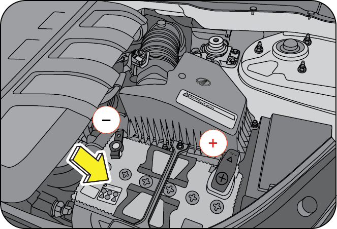
Your vehicle is equipped with a Mahindra genuine battery. For longer, trouble-free operation, keep the top of the battery clean and dry. Also, make certain the battery cables are always tightly fastened to the battery terminals.
If you see any corrosion on the battery or terminals, remove the cables from the terminals and clean with a wire brush. You can neutralize the acid with a solution of baking soda and water. To prevent corrosion, apply petroleum jelly to the battery terminals. Tighten loose terminals and hold down clamp nuts only enough to keep the battery firmly in place. Tightening excessively may damage the battery terminals.
- Keep the battery securely mounted
- Keep the battery top clean and dry
- Keep the terminals and connections clean, tight, and coated with petroleum jelly or terminal grease
- Rinse any spilled electrolyte from the battery immediately with a solution of water and baking soda
If the vehicle is not going to be used for an extended time, disconnect the battery cables.
15.16.2 Battery Charge Indicator - Amaron (if equipped)
A battery charge indicator is provided for Amaron batteries to view the charge status at a glance.
Green indicates the battery is okay, and light blue indicates battery needs recharge or technical assistance from Amaron.
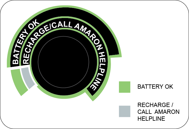
15.16.3 Battery Charge Indicator - Exide (if equipped)
A battery charge indicator is provided for Exide batteries to view the charge status at a glance.
Three charge indicators are provided which give the following information;
- OK (Battery condition good)
- Needs charging
- Add distilled water
A battery charge indicator is provided for Exide batteries to view the charge status at a glance.
Three charge indicators are provided which give the following information;
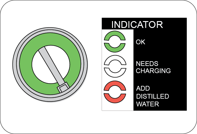
Battery charge indicator gives the indication of the closest cell where it is located. The battery may be defective in case there is any internal shorting of other cells which needs the attention of the Authorised battery dealer.
Do not disconnect battery terminals while the engine is running. This will adversely affect all electronic controllers.
While removing the battery, always disconnect the negative terminal first. And while installing the battery, ensure the negative terminal is connected last.
It is recommended that the negative battery cable terminal be disconnected from the battery if you plan to store your vehicle for an extended period of time. This will minimize the discharge of your battery during storage.
Battery fluid is a corrosive acid solution; do not allow battery acid to contact eyes, skin or clothing. Don't lean over battery when attaching clamps or allow the clamps to touch each other. If acid splashes in the eyes or on the skin, flush contaminated area immediately with large quantities of water.
A battery generates hydrogen gas which is flammable and explosive. Keep any flame or spark away from the vent holes.
Keep batteries out of reach of children. Battery posts, terminals and related accessories contain lead and lead components. Wash hands after handling batteries.
If the battery has been disconnected or a new battery has been installed, the clock and the preset radio stations must be reset once the battery is reconnected.
Always dispose of automotive batteries in a responsible manner. Follow your local state standards for disposal. Call your local authorized recycling centre to find out more about recycling automotive batteries.
The replacement battery must meet the specification of the originally fitted battery.
15.16.4 Checking the Electrolyte Level
Check the electrolyte level and specific gravity at intervals of three months. Check all the six cells for proper electrolyte levels. If the level is below the lower marker, add distilled water until the level reaches the upper marker.
Adding distill water;
- Remove the vent plugs
- Add distilled water to all the cells that require the fluid
- Secure the plugs properly
15.17 Vehicle Appearance, Care and Protection
15.17.1 Washing the Exterior
- Wash your vehicle regularly with cool or lukewarm water and a neutral pH soap
- Never use strong household detergents or soap, such as dish washing or laundry liquid. These products can discolor and spot painted surfaces
- Never wash a vehicle that is “hot to the touch” or during exposure to strong, direct sunlight
- Always use a clean sponge or car wash mitt with plenty of water for best results
- Dry the vehicle with a chamois or soft terry cloth towel in order to eliminate water spotting
- It is especially important to wash the vehicle regularly during the winter months, as dirt and road salt are difficult to remove and cause damage to the vehicle
- Immediately remove items such as gasoline, diesel fuel, bird droppings and insect deposits; they can cause damage to the vehicle's paint work and trim over time
15.17.2 Exterior Chrome
- Wash the vehicle first, using cool or lukewarm water and a neutral pH shampoo
- Use the custom bright metal cleaner, available from your Authorized Mahindra Dealer. Apply the product as you would wax to clean chrome parts; allow the cleaner to dry for a few minutes, and then wipe off the haze with a clean, dry rag
- Never use abrasive materials such as steel wool or plastic pads as they can leave scratches on the chrome surface
- After polishing the chrome parts, you can also apply a coating of Premium Liquid Wax, available from your Authorized Mahindra Dealer, or an equivalent quality product to help protect from environmental effects
15.17.3 Paint Chips
- Mahindra dealers have the exact touch-up paint to match your vehicle's color.
- Take your vehicle to an Authorized Mahindra Dealer for paint touch-up or paint repairs.
- Remove particles such as bird droppings, tree sap, insect deposits, tar spots, road salt and industrial fallout before repairing paint chips.
- Always read the instructions before using the products.
15.17.4 Aluminium Wheels And Wheel Covers (if equipped)
Aluminium wheels and wheel covers are coated with a clear coat paint finish. In order to maintain their shine;
- Clean weekly with wheel and tyre cleaner, which is available from an Authorized Mahindra Dealer. Heavy dirt and brake dust accumulation may require agitation with a sponge. Rinse thoroughly with a strong stream of water
- Never apply any cleaning chemicals to hot or warm wheel rims or covers
- Do not use hydro-fluoric acid-based or high caustic based wheel cleaners, steel wool, fuels or strong household detergents
15.17.5 Engine Compartment
Engines are more efficient when they are clean since grease and dirt build-up make the engine warmer than normal.
Even though all the electrical and electronic sensors/actuators, etc. are water resistant/sealed, care must be taken, and avoid direct water jet on these items during car wash.
When washing;
- Take care when using a power washer to clean the engine compartment.
- Do not spray a hot engine with cold water to avoid cracking the engine block or other engine components
- Never wash or rinse the engine while it is running; this may lead to internal engine damage
- Do not wash the engine compartment with high pressure water, this could damage the electrical components, wiring or connectors leading to short circuits
15.17.6 Plastic (Non-painted) Exterior Parts
Use only approved products to clean plastic parts. These products are available with your authorized dealer. You can use these cleaners;
- For routine cleaning of plastic parts
- For tar or grease spots
- For plastic head lamp lenses
15.17.7 Windows and Wiper Blades
The front/rear windshield, side windows and the wiper blades should be cleaned regularly. If the wipers do not wipe properly, substances on the vehicle's glass or the wiper blades may be the cause. These may include hot wax treatments used by commercial car washes, water repellent coatings, tree sap, or other organic contamination; these contaminants may cause squeaking or chatter noise from the blades, and streaking and smearing of the windshield.
To clean these items follow these tips;
- The windshield, rear windows and side windows may be cleaned with a non-abrasive cleaner such as Clear Spray Glass Cleaner, available from an Authorized Mahindra Dealer.
- The wiper blades can be cleaned with alcohol or Premium Windshield Washer Concentrate, available from an Authorized Mahindra Dealer. This washer fluid contains special solution in addition to alcohol which helps to remove the hot wax deposited on the wiper blade and windshield. Be sure to replace wiper blades when they appear worn or do not function properly.
- Do not use abrasives, as they may cause scratches.
- Do not use fuel, kerosene, or paint thinner to clean any glass parts.
If you cannot remove those streaks after cleaning with the glass cleaner or if the wipers chatter and move in a jerky motion, clean the outer surface of the windshield and the wiper blades using a sponge or soft cloth with a neutral detergent or mild-abrasive cleaning solution. After cleaning, rinse the windshield and wiper blades with clean water. The windshield is clean if beads do not form when you rinse the windshield with water.
Do not use sharp objects, such as a razor blade, to remove decals, as it may cause damage to the glass or rear windshield heater grid lines (if equipped).
15.17.8 Instrument Panel/Interior Trim and Cluster Lens
Do not use chemical solvents or strong detergents when cleaning the steering wheel or instrument panel.
Clean the instrument panel, interior trim areas and cluster lens with a clean and damp white cotton cloth, then with a clean and dry white cotton cloth; you may also use Dash and Vinyl Cleaner on the instrument panel and interior trim areas.
- Avoid cleaners or polishes that increase the gloss of the upper portion of the instrument panel. The dull finish in this area helps protect the driver from undesirable windshield reflection
- Do not use household or glass cleaners as these may damage the finish of the instrument panel, interior trim and cluster lens
If a staining liquid like coffee/juice has been spilled on the instrument panel or on the interior trim surfaces, clean as follows;
- Wipe up spilled liquid using a clean white cotton cloth
- Apply Vinyl Cleaner to the wiped area and spread around evenly
- Apply cleaner to a clean white cotton cloth and press the cloth onto the soiled area and allow this to set in at room temperature for 30 minutes
- Remove the soaked cloth, and if it is not soiled badly, use this cloth to clean the area by a rubbing motion for 60 seconds
- Following this, wipe area dry with a clean white cotton cloth
15.17.9 Interior
For fabric, carpets, cloth seats, safety belts and seats:
- Remove dust and loose dirt with a vacuum cleaner
- Remove light stains and soil with Carpet and Upholstery Cleaner
- If grease or tar is present on the material, spot-clean the area first with Stain Remover
- Do not use household cleaning products or glass cleaners, which can stain and discolor the fabric and affect the flame retardant abilities of the seat materials
- Do not use cleaning solvents, bleach or dye on the vehicle's safety belts, as these actions may weaken the belt webbing.
15.17.10 Leather Seats (where applicable)
Your leather seating surfaces have a clear, protective coating over the leather.
- To clean, use a soft cloth with a leather and vinyl cleaner. Dry the area with a soft cloth.
- To help maintain its resiliency and color, use the leather care kit, available from an Authorized Mahindra Dealer.
- Do not use household cleaning products, alcohol solutions, solvents or cleaners intended for rubber, vinyl and plastics, or oil/petroleum-based leather conditioners. These products may cause premature wearing of the clear, protective coating.
In some instances, color or dye transfer can occur when wet clothing comes in contact with leather upholstery. If this occurs, clean the leather immediately to avoid permanent staining.
15.17.11 Underbody
Flush the complete underside of your vehicle frequently. Keep body and door drain holes free from packed dirt. You can also use an anti-corrosion spray for the underbody to avoid rusting and corrosion especially for vehicles in coastal places.
15.18 Air Conditioning System Maintenance
Your vehicle's air-conditioning is a sealed system. Any major maintenance, such as recharging should be done by a qualified technician. However, you can do a few things by yourself to make sure the air-conditioning works efficiently.
Run the air-conditioning system at least once a week, even during the cold weather months. Run it for at least ten minutes with the engine running at normal operating temperature. This circulates the lubricating oil contained in the refrigerant.
Whenever you get the air-conditioning system serviced, make sure the service facility uses a refrigerant recycling system. This system captures the refrigerant for re-use. Releasing the refrigerant into the atmosphere may cause damage to the environment.
15.19 Vehicle Storage
If you are leaving your vehicle for more than 2 weeks you may want to take steps to protect your battery. Disconnect the negative cable from the battery. Anytime you store your vehicle, or keep it out of service (i.e. vacation) for two weeks or more, run the air conditioning system at idle for about five minutes in the fresh air mode and high blower speed setting. This will ensure adequate system lubrication to minimize the possibility of compressor damage when the system is started again.
It is recommended storing the vehicle in a covered, clean, dry, well leveled, ventilated and closed place.
If the engine is being started after a very long period of non-use, warm up the engine at an idle speed for 2-3 minutes before driving the vehicle.
15.20 Winter Care
15.20.1 Dealing With Ice
Make sure you have window ice scrapers and de-icers for the locks. When you're stuck, having a small shovel is useful to dig out of the snow. The weight of a bag of sand in the trunk will give added traction in rear-wheel drive vehicles and can be used to sprinkle on the snow and ice to gain better traction. And don't forget personal protection such as a warm coat, hat, gloves and a blanket, in case you get stuck in a storm.
15.20.2 Keep Enough Fuel in the Tank
Never let the fuel level in the tank drop below the half-full mark. A sudden storm with unexpected heavy rains could leave you stranded for hours. Having adequate fuel supply will allow you to idle the engine from time to time to keep warm.
- Tap the ice on the window to crack it or chip it for a good place to start scraping. You could end up cracking more than the ice and end up with a cracked or shattered windshield/window
- Pour warm or hot water on the windshield to melt ice. This will crack your windshield
15.20.3 During Winter Storage
Start the engine occasionally, here are a few pointers to keep in mind;
- Run it in a well ventilated area. Carbon monoxide can build up quickly
- Run for a minimum of 20 minutes to allow the engine to come up to the normal operating temperature. This will allow the oil to circulate and will also open up the thermostat so that your radiator anti-freeze circulates as well
- Start up the air conditioner and/or heater and run them for 10 minutes or so. Again, circulating fluids is essential for a good life of the system
- If your vehicle has power steering, you may want to turn the wheels a few times to keep the fluids flowing
Wash and wax your car to provide an extra layer of protection to your paint.
Use a good conditioner on all vinyl and rubber parts to prevent them from drying out.
Clean the glass, shampoo the carpets, dig in between the seats to see what's there, clean the upholstery in all the nooks and corners.
Check all hoses and wires to make sure everything is in good condition and replace any that need to be. The last thing to do is to make sure the internal components of the engine remain lubricated and don't corrode.
15.21 Wiper Blades
Lift the wiper arm from its position. Expose the blade lip for inspection. Clean the wiper blade lips with water applied with a soft sponge. If the wiper blade is not wiping the glass satisfactorily or is worn-out, cut, cracked or bulging get it replaced at an Authorized Mahindra Dealer.
- Lift the arm and position the wiper blade at right angles to the wiper arm
- Press the retaining clip in the opposite direction, disengage the wiper blade and pull it off the arm
- Hold the end of the rubber and pull until the tabs are free of the metal support
- Carefully insert the new blade rubber. Then install the blade assembly in the reverse order of removal
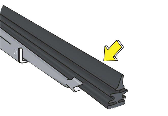
To prevent damage to the windshield, don’t let the wiper arm slap down on to it.
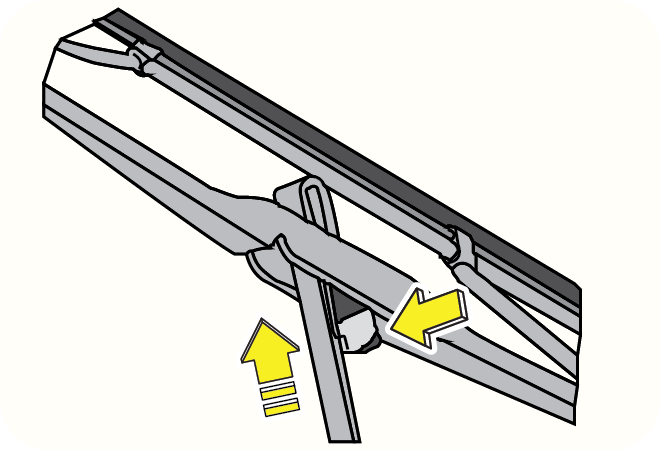
15.22 Head Lamp Bulb Replacement
The head lamp bulb can be replaced without removing the head lamp assembly from the vehicle. The head lamp assembly has been removed here for illustration purpose only.
15.22.1 Projectile Head lamp
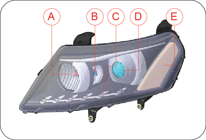
| A | Head lamp High Beam | D | Head lamp Low Beam |
| B | Static Bending Lamp | E | Turn Signal Lamp |
| C | Parking Lamp |
To replace the head lamp high beam/low beam bulb;
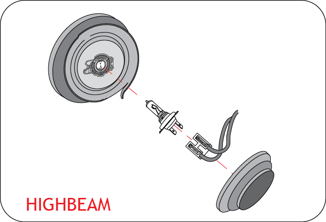
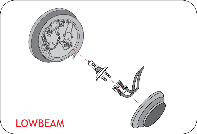
Do not touch the new bulb with your fingers. Oil contamination will severely shorten bulb life. If the bulb comes in contact with any oily surface, clean the bulb with rubbing alcohol.
To avoid burning yourself, do not replace the light bulbs when they are hot. Halogen bulbs have pressurized gas inside and are to be handled with special care. Mishandling it may cause the bulb to burst or shatter. Hold the bulb with its metal/plastic holder/base and do not touch the glass part with bare hands.
15.22.2 Non Projectile Head lamp
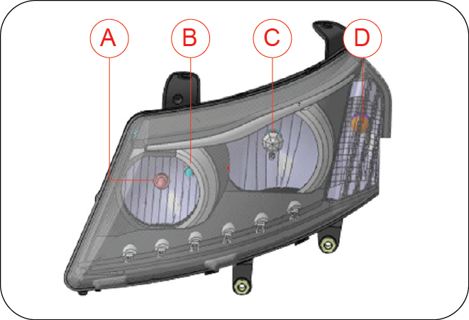
| A | Head lamp High Beam | C | Head lamp Low Beam |
| B | Parking Lamp | D | Turn Signal Lamp |
15.23 Scheduled Maintenance
The scheduled maintenance jobs listed in the “Scheduled Maintenance Chart” are those required to be carried out at regular pre-determined intervals.
To make sure that your vehicle runs efficiently all the time, follow the maintenance schedule. The service interval for the scheduled maintenance is determined by the odometer reading or by time interval, whichever comes earlier. Take your vehicle to a Authorized Mahindra service station only. Trained technicians and genuine Mahindra parts at Mahindra Authorized service stations are best for your vehicle. They will perform all the scheduled maintenance jobs reliably and economically. Inadequate, incomplete & insufficient servicing may result in problems.
The owner should retain records/documents that proper maintenance has been performed as prescribed.
A majority of the time taken in servicing goes in identifying problems. You can help your technician reduce this time by telling him about the conditions you experienced in your vehicle. For example;
- When experiencing a problem, try to listen to any unusual noises made by the vehicle
- The engine coolant temperature being continuously higher than the normal
- Note if the vehicle is sluggish or feels different than normal
- Tell the technician about the circumstances prior to the moment you experienced the problem
It is recommended using Mahindra supplied replacement parts for maintenance or repairs. The recommended service schedule is listed in the following chart.
15.24 Maintenance Schedule Chart
| Description | Change Interval | Distance Covered in kms | ||||||||||
|---|---|---|---|---|---|---|---|---|---|---|---|---|
| 5000 | 10000 | 20000 | 30000 | 40000 | 50000 | 60000 | 70000 | 80000 | 90000 | 100000 | ||
| I = Inspect and Correct R = Replace C = Clean | ||||||||||||
| Engine | ||||||||||||
| Engine Oil 1 | Replace at 5k, 20k and then every 20k kms | R | I | R | I | R | I | R | I | R | I | R |
| Engine Oil Filter | Replace at 5k, 20k and then every 20k kms | R | R | R | R | R | R | |||||
| Auto Tensioner & Belts | Replace every 100k kms | I | I | R | ||||||||
| Coolant 3 | Replace every 80k kms | I | I | I | I | I | I | I | I | R | I | I |
| Air, Fuel and Exhaust | ||||||||||||
| Air Filter Element 5 | Replace every 40k kms | R | R | |||||||||
| Fuel Filter Cartridge (Bosch) | Replace every 20k kms | R | R | R | R | R | ||||||
| Fuel Filter Cartridge (SugEfi) | Replace every 30k kms | R | R | R | ||||||||
| Exhaust Pipe Mountings and Damage/Leakage | Inspect every 10k kms | I | I | I | I | I | I | I | I | I | I | |
| Water sediments - Drain fuel filter (Bosch) | Inspect at 5k, 10k, then every 20k kms | I | I | I | I | I | I | |||||
| Water sediments - Drain fuel filter (SugEfi) | Inspect at 5k, 10k, 20k, then every 20k kms | I | I | I | I | I | I | I | I | |||
| Transaxle | ||||||||||||
| Transaxle Oil 2 | Replace every 100k kms | R | ||||||||||
| All Wheel Drive (AWD) # | ||||||||||||
| Rear Axle (IRDA) OIl 2 | Replace at 5k, 50k and then every 50k kms | R | R | R | ||||||||
| Transfer Case (PTU) OIl 2 | Replace at 5k, 50k and then every 50k kms | R | R | R | ||||||||
| Brakes | ||||||||||||
| Brake & Clutch Fluid - Level & Leak Check 4 | Replace every 40k kms | I | I | R | I | I | I | R | I | I | ||
| Parking Brake | Inspect at 5k, 20k, then every 20k kms | I | I | I | I | I | I | |||||
| Front & Rear Brake Pads/Caliper | Inspect every 10k kms | I | I | I | I | I | I | I | I | I | I | |
| Suspension | ||||||||||||
| Front Suspension Bolts Torque | Inspect at 5k, 20k, then every 20k kms | I | I | I | I | I | I | |||||
| Rear Suspension Bolts Torque | Inspect at 5k, 20k, then every 20k kms | I | I | I | I | I | I | |||||
| Front Suspension Bushes | Inspect every 40k kms | I | I | |||||||||
| Rear Suspension Arms & Links | Inspect every 40k kms | I | I | |||||||||
| Steering | ||||||||||||
| Power Steering Fluid - Level & Leak Check | Inspect every service | I | I | I | I | I | I | I | I | I | I | I |
| Wheel Alignment * | Inspect if abnormal conditions are noticed | I | I | |||||||||
| Electrical | ||||||||||||
| Battery Electrolyte Level & Specific Gravity | Inspect every 10k kms | I | I | I | I | I | I | I | I | I | I | |
| All Lamps, Horns, Wipers and Washers | Inspect every 10k kms | I | I | I | I | I | I | I | I | I | I | |
| Head Lamp Aiming | Inspect every 10k kms | I | I | I | I | I | I | I | I | I | I | |
| HVAC | ||||||||||||
| Particle Filter | Replace every 10k kms | R | R | R | R | R | R | R | R | R | R | |
| Final Inspection | ||||||||||||
| Tyre Pressure | Inspect every service | I | I | I | I | I | I | I | I | I | I | I |
| Underbody Mounting Bolts for Tightness | Inspect every 10k kms | I | I | I | I | I | I | I | I | I | I | |
| Road Test | Inspect every service | I | I | I | I | I | I | I | I | I | I | I |
| Tyre Rotation * | Inspect every 10k kms | I | I | I | I | I | I | I | I | I | I | |
| Service Reminder Indicator Reset | Inspect every service | I | I | I | I | I | I | I | I | I | I | I |
| Legend: | ||||||||||||
| 1- Change as per the km or 1 year whichever earlier | 4- Change brake and clutch fluid at every 40,000 km or 2 years whichever earlier | |||||||||||
| 2- Change as per the km or 2 years whichever earlier | 5- Under extreme operating conditions replace air filter every 20,000 kms | |||||||||||
| 3- Change as per the km or 3 years whichever earlier | #- If Applicable | |||||||||||
| *- on chargeable basis | ||||||||||||