Issue Date: March 2020
NOTE: Carefully read, understand and follow the instructions provided in this manual, and keep it in a safe place for future reference.
If you have any doubt whatsoever regarding the use or care of your vehicle, please visit your Authorised Mahindra Dealer for
assistance or advice.
This Owner's Manual should be considered as an integral part of the vehicle and should remain with the vehicle.

MAHINDRA & MAHINDRA LTD., GATEWAY BUILDING, APOLLO BUNDER, MUMBAI - 400 039
www.mahindra.com
| Important Information – Quick Reference | |
|
We
strongly urge that you read the information provided in pages referred
hereunder which will help in road safety and prevent
inconvenience
|
|
1
|
Warranty Coverage...............................................................................................................................................
|
Refer WI&MG* (P.g. 12)
|
|
2
|
Roadside Assistance ............................................................................................................................................
|
Refer WI&MG* (P.g. 8)
|
|
3
|
Schedule Service (Free/Paid)...........................................................................................................................
|
Refer WI&MG* (P.g. 22)
|
|
4
|
Maintenance Schedule Chart...........................................................................................................................
|
Refer WI&MG* (P.g. 24)
|
|
5
|
Lubricants and Capacities...........................................................................................................................
|
Refer WI&MG* (P.g. 27)
|
|
6
|
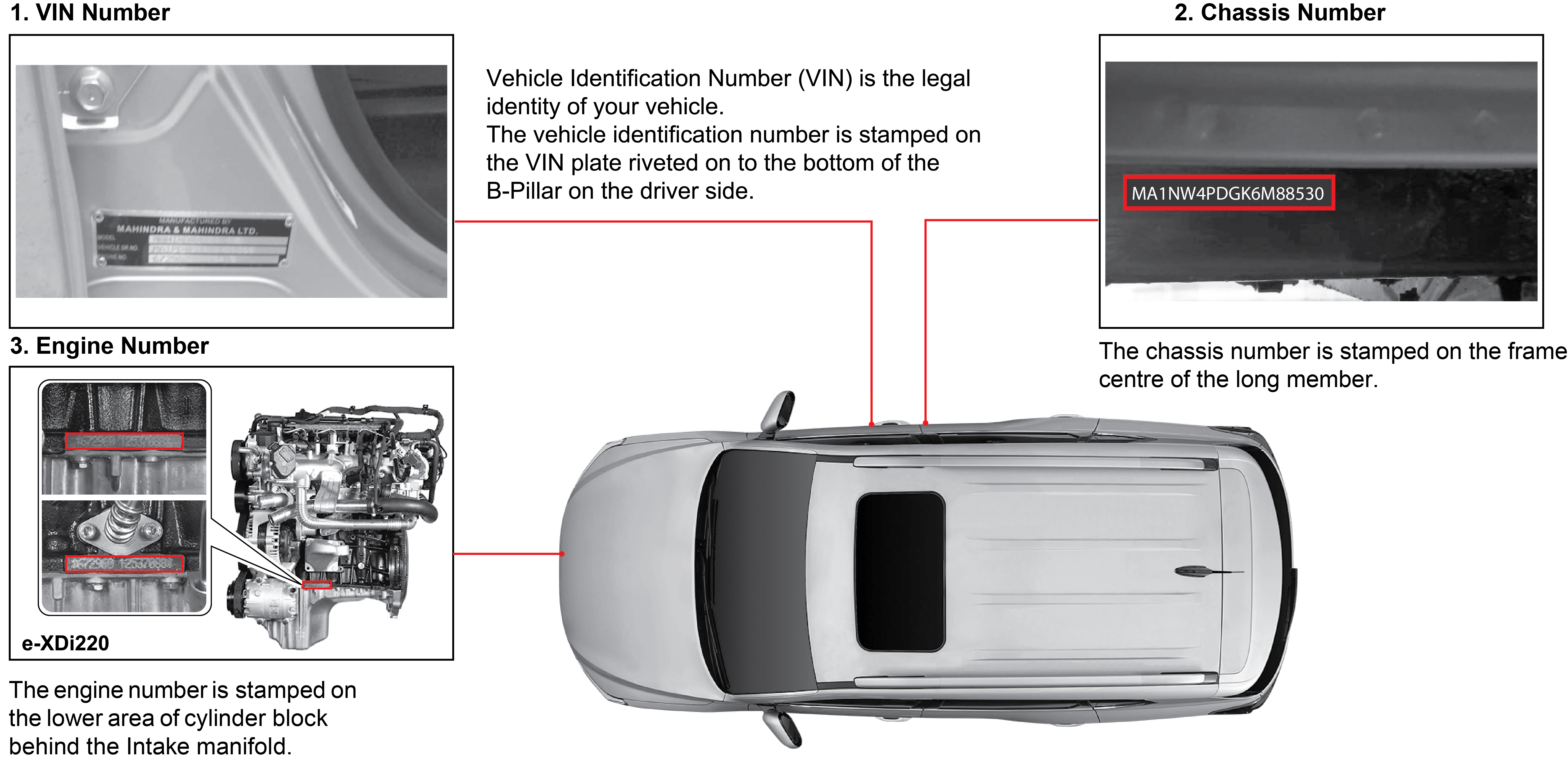
Location Of Vehicle Identification Number (VIN)......................................................................................
|
Refer (P.g. 1-11)
|
|
7
|
Location Of Fuse Box And Fuse Details........................................................................................................
|
Refer (P.g. 8-12)
|
|
8
|
Changing A Flat Tyre.............................................................................................................................................
|
Refer (P.g. 7-10)
|
|
9
|
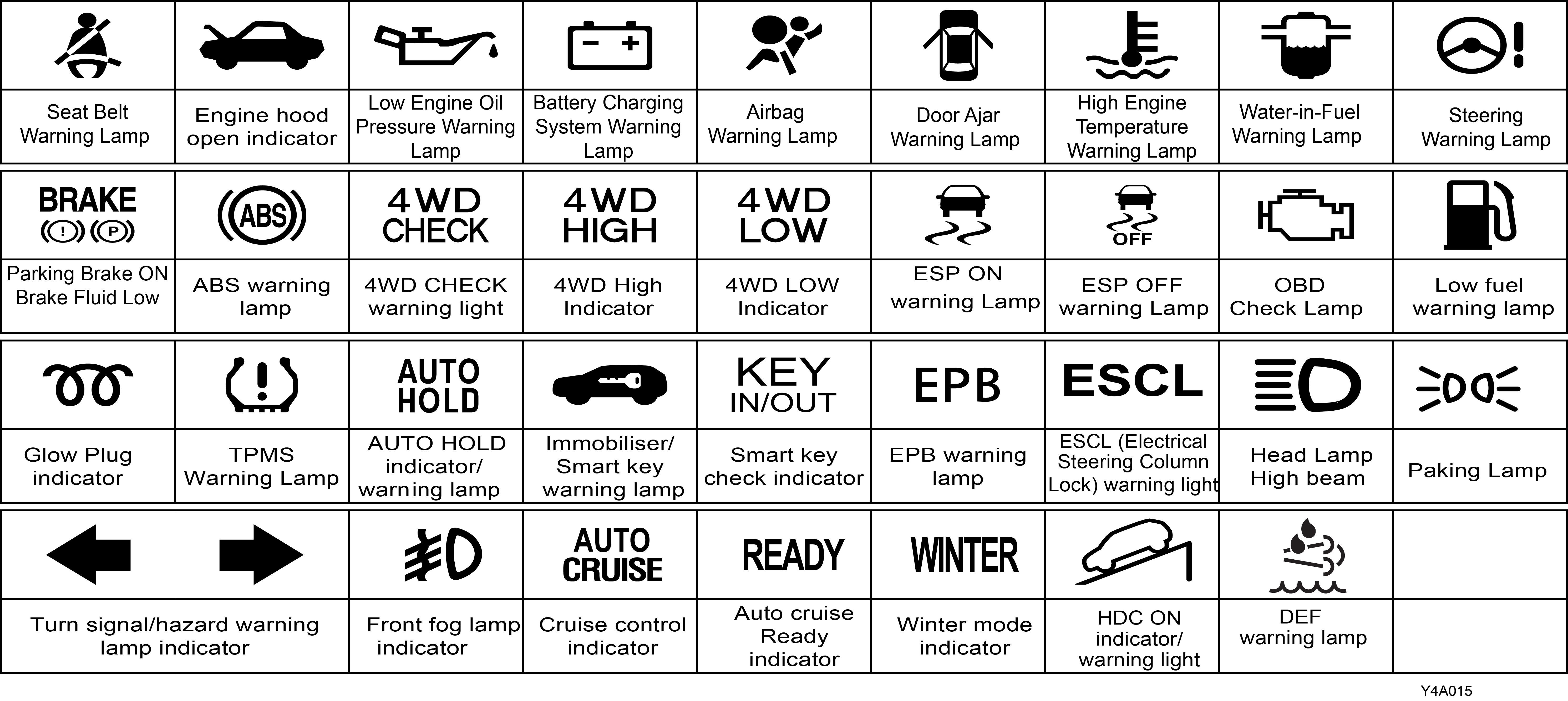
Understanding The Warning Lamps.............................................................................................................
|
Refer (P.g. 6-6)
|
|
10
|
Use Of Seats Belts And Child Restraint.......................................................................................................
|
Refer (P.g. 2-3)
|
|
11
|
Understanding The Airbag Function..............................................................................................................
|
Refer (P.g. 2-6)
|
|
12
|
If Your Vehicle Is Submerged...........................................................................................................................
|
Refer (P.g. 4-25)
|
|
13
|
Driving Through Water.......................................................................................................................................
|
Refer (P.g. 4-25)
|
|
14
|
Opening And Closing The Hood/Bonnet.....................................................................................................
|
Refer (P.g. 5-31)
|
|
15
|
Location Of Battery And Its Maintenance..................................................................................................
|
Refer (P.g. 8-12)
|
|
*Warranty Information & Maintenance Guide
|
1 GENERAL INFORMATION
1.1 Introduction
Dear Customer,
Congratulations on purchasing Mahindra ALTURAS G4. Your vehicle has been designed to provide years of safe and dependable service, as long as it is used and maintained in
accordance with the instructions provided in this manual.
All persons who will use and/or maintain this vehicle must read, understand and follow all warnings and instructions provided
in this manual. This Owner's Manual should be considered an integral part of the vehicle and should remain with the vehicle.
However, nothing in this manual, and none of the safety devices installed in the vehicle, are a substitute for careful operation
and common sense. Always make sure that your vehicle is in optimum working order, and take note of the road and weather conditions
under which you are using your vehicle.
If you have any questions concerning the proper use or maintenance of your vehicle, please call your Authorised Mahindra Dealer.
Alternatively, you can contact Mahindra at:
| • | 1800-209-6006 (Toll free) |
| • | customercare@mahindra.com |
We extend our best wishes for safe and pleasurable motoring.
Sincerely,
1.2 Servicing and Summary Data
| • | For all issues concerning the vehicle and for any need of spare parts, contact only the Authorised Mahindra Dealer network |
| • | We recommend you always use genuine Mahindra spare parts when performing repairs on the vehicle |
| • | We suggest that you record the vehicle data in the Warranty Information & Maintenance Guide for future references |
1.3 Safety Symbols
Carefully read, understand and follow the safety symbols/ instructions given in this manual.
Legend of the Symbols
To emphasise information and procedures regarding safety, use, maintenance, etc., the following symbols are used throughout
the manual:

DANGER indicates an imminently hazardous situation which, if not avoided, will result in death or serious injury.

WARNING indicates a potentially hazardous situation which, if not avoided, could result in death or serious injury.

CAUTION indicates a potentially hazardous situation which, if not avoided, may result in minor or moderate injury and/or property damage.

NOTICE indicates important information relevant to the vehicle, the vehicle's use or to sections of this manual to which particular
attention must be paid for optimum use of the vehicle.
If you see this symbol, it indicates “no,” “do not,” “do not do this,” or “never”.
1.4 General Safety Information and Instructions
Failure to follow the warnings and instructions provided in this manual could result in failure of the vehicle, an accident
and/or serious personal injury.
| 1. | Carefully read, understand and follow the warnings and instructions given in this manual. This manual is an essential part of the product. Keep it in the vehicle’s glove box for future reference. |
| 2. | Please note that throughout this manual, reference is made that “an accident” could occur. An accident could cause you or a bystander to sustain personal injury, or result in property damage. |
| 3. | Never use a mobile phone or any device with headphone while driving. This may take your focus off the road and lead to accidents. |
| 4. | Please be advised that many service and repair tasks require specialised knowledge, tools and experience. General mechanical aptitude may not be sufficient to properly service or repair your vehicle. If you have any doubt whatsoever regarding the ability to properly service or repair your vehicle, please contact your Authorised Mahindra Dealer or a qualified technician. |
| 5. | Inspect the seat belt system periodically, checking for cuts, frays or wear in the seat belt webbing, or loose buckles, retractors, anchors or other loose parts. Damaged parts must be replaced immediately. |
| 6. | Always start and operate the engine in a well-ventilated area. If in an enclosed area, vent the exhaust to the outside. Do not modify or tamper with the exhaust system. |
| 7. | Examine tyres for excessive tread wear and uneven wear patterns. Check for stones, nails, glass, or other objects lodged in the tread and check sidewalls for any cuts, cracks, or other signs of wear. Replace as necessary. |
| 8. | Always maintain the safety labels affixed to your vehicle in a good legible condition. |
| 9. | All signal lamps, buzzers, shields, guards and other protective safety devices must always remain in place and in good, proper working condition. |
| 10. | The lifespan of Mahindra products depend on many factors. Improper use, abuse or harsh use in general may compromise the integrity of the vehicle and significantly reduce its lifespan. The vehicle is also subject to wear over a period of time. Please have your vehicle regularly inspected by an Authorised Mahindra Dealer. If the inspection reveals any damage or excessive wear, immediately replace or have the component serviced. |
| 11. | We recommend that you use only genuine parts supplied by Mahindra. The use of non-Mahindra parts will not be covered by warranty. |
| 12. | Never crawl under or be in close proximity to the vehicle when it is lifted off the ground (by a jack), unless the vehicle is properly supported with jack stands, wheel chocks and other appropriate safety devices. |
| 13. | Never attempt any repairs or adjustments to any component while the vehicle is in motion. Always switch off the engine, and wait for the engine to come to a complete stop before performing any repairs or adjustments. |
| 14. | The vehicle identification plates are the only legal identification reference, hence it is necessary to keep them in good condition. Never modify data on the plates or remove them. The customer is responsible for any possible tampering with the plates, which will immediately void the warranty. |
| 15. | Do not attempt sharp turns, abrupt manoeuvres, or other unsafe driving actions that can cause loss of vehicle control. When the vehicle is fully loaded, drive at a slow speed, especially when turning. Note that the centre of gravity of the vehicle changes when the vehicle is fully loaded, and also if luggage is mounted on the roof carrier. |
1.5 To Owners of a Mahindra Vehicle
When first driving the vehicle after long periods of non-use, you may experience a temporary drive disturbance. This is a
characteristic of the tyres and should be no reason for concern. The condition should correct itself within 5-15 kms. of driving.
If the disturbance persists, have the tyres checked by an Authorised Mahindra Dealer.
Driving and Alcohol
Your driving ability can be seriously impaired by alcohol even if the blood alcohol level is far below the legal minimum.
Drunken driving is one of the most frequent causes of accidents.
Never drink and drive. Drinking and driving will lead to an accident resulting in serious personal injury.
Driving and Drugs/Medication
Your driving ability can be seriously impaired through the use of prescription or non-prescription drugs or medication (even
cough syrup). If you are taking any sort of drug or medication, be sure that it will not affect your driving ability.
Mobile Phones Warning
Use of electronic devices such as mobile phones, computers, portable radios or other by the driver while driving is dangerous.
In exceptional condition, if use of a mobile phone is necessary despite this warning, use a hands free system to ensure that
the hands are free to drive the vehicle. Even handsfree do not ensure that due to distraction an accident will not happen.
Please comply with the legal regulations concerning the use of communication equipment in vehicles in your country.
Driving Long Distances
When you are driving over long distances, follow these tips so that you have a safe journey:
| • | Lack of sleep or fatigue will impact your ability to drive safely |
| • | Exercise your eyes by shifting the focus of your eyes to different parts of the road |
| • | Use stimulating beverages such as coffee or tea |
| • | Relax and stay calm |
| • | Take breaks at regular intervals |
Protecting Our Environment
All of us should play our part in protecting our environment. Judicious vehicle usage and ensuring hazardous waste disposal
(including cleaning and lubrication fluids) are important steps towards this initiative.
Mahindra vehicles conform to existing emission norms (standards). Adhering to the periodical maintenance schedule and using
Mahindra genuine parts will help retain emission performance of the vehicle and is a pre-requisite for emissions warranty
coverage.
Servicing
If you have any questions concerning the proper use or maintenance of your vehicle, please call your Authorised Mahindra Dealer.
A list of dealers can be found on the Internet.
Alternatively, you can contact us on 1800-209-6006 / customercare@mahindra.com.
Running-in
Driving smoothly during first 1,000 kms. will help to prevent abnormal and premature system wear. Proper running-in will improving
the life of drivetrain and vehicle components.
A new engine may consume more oil during the first 1,000 kms. of running. This should be considered as a normal part of break-in
and not interpreted as any problem with the engine.
Mahindra Genuine Parts
Mahindra uses high quality parts for building the vehicles.
In the event that any parts need replacement, we recommend that you use only Mahindra genuine parts.
Non-Mahindra parts may harm vehicle performance and will not be covered by your Mahindra warranty.
To avoid counterfeit parts and to protect our brand image, Mahindra genuine parts are packed in a branded carton. Look for
the “Mahindra Genuine Parts” logo.
Any unauthorised modifications or alterations to this vehicle or failure to use appropriate specification and quality spare
parts could seriously affect vehicle roadworthiness and safety leading to an accident, resulting in serious injury.
Mahindra Genuine Accessories
A wide selection of quality accessories are available through your Authorised Mahindra Dealer. These accessories have been
specifically engineered to allow you to personalise your vehicle to suit your requirements and complement its style and aerodynamic
appearance.
Each accessory is made from high quality materials and meets Mahindra's rigid engineering and safety specifications. Every
Mahindra accessory installed according to the Mahindra installation provisions comes with the respective accessory warranty.
Consult your Authorised Mahindra Dealer for detailed information about accessories available for your specific model variant.
For maximum vehicle performance and safety considerations, always keep the following information in mind:
| • | The company does not take any responsibility for consequential damages / injuries resulting due to fitment of unauthorised aftermarket accessories and / or tapping / cutting wires in the wiring harness |
| • | When adding accessories, equipment, passengers and luggage to your vehicle, do not exceed the total weight capacity of the vehicle or of the front and rear axle. Consult Authorised Mahindra Dealer for specific weight information |
| • | Bull bars and nudge guards are not recommended |
| • | Accessories causing any change in vehicle specifications like wheel rims, bull bars, etc., may affect the performance of safety systems |
| • | Mobile communication systems such as two-way radios, telephones and theft alarms that are equipped with radio transmitters and installed in your vehicle should comply with the local regulations and should be installed only by your Authorised Mahindra Dealer |
Vehicle Safety
When leaving your vehicle unoccupied:
| • | Always remove the smart key when you park the vehicle |
| • | Close all the windows completely and lock all the doors |
| • | Do not leave any valuables in your vehicle. If you must leave something in your vehicle, hide them and securely lock all the doors |


1.7 Technical Specifications
|
Descriptions |
Alturas G4 2WD |
Alturas G4 2WD High |
Alturas G4 4WD |
|||
|---|---|---|---|---|---|---|
|
General |
Overall length (mm) |
4,850 |
||||
|
Overall width (mm) |
1,960 |
|||||
|
Overall height (mm) (with Roof Rails) |
1,845 |
|||||
|
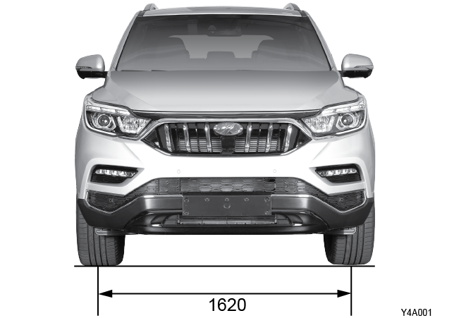
Wheel track |
1,620 |
|||||
|
Fuel |
Diesel BS VI |
|||||
|
Fuel tank capacity (ℓ) |
70L |
|||||
|
DEF tank capacity (ℓ) |
25L |
|||||
|
Minimum turning radius |
5.5m |
|||||
|
Engine D22DTR |
Numbers of cylinders/Compression ratio |
4 / 15.5:1 |
||||
|
Total displacement (cc) |
2,157 |
|||||
|
Camshaft arrangement |
DOHC |
|||||
|
Max. power |
133.1 kW / 3,800 rpm |
|||||
|
Max. torque |
420 Nm / 1,600 ~ 2,600 rpm |
|||||
|
Idle speed |
720 ± 50 rpm |
|||||
|
Cooling system |
Water-cooled / forced circulation |
|||||
|
Coolant capacity (ℓ) |
10.2 |
|||||
|
Lubrication type |
Gear pump, forced circulation |
|||||
|
Max. oil capacity (ℓ) |
6.0 |
|||||
|
Turbocharger and cooling type |
Turbocharger, air-cooled |
|||||
|
Automatic Transmission |
Model |
Electronic, 7-speed |
||||
|
Gear ratio |
1st |
4.377 |
||||
|
2nd |
2.859 |
|||||
|
3rd |
1.921 |
|||||
|
4th |
1.368 |
|||||
|
5th |
1.000 |
|||||
|
6th |
0.820 |
|||||
|
7th |
0.728 |
|||||
|
Reverse 1st |
3.416 |
|||||
|
Reverse 2nd |
2.231 |
|||||
|
Transfer Case |
Model |
— |
Part-time |
|||
|
Type |
— |
Planetary gear type |
||||
|
Gear ratio |
High (4H) |
— |
1.000 : 1 |
|||
|
Low (4L) |
— |
2.483 : 1 |
||||
|
Power Steering |
Type |
Rack and pinion |
||||
|
Steering angle |
Inner / Outer |
39.6° / 33.6° |
||||
|
Front Axle |
Drive shaft type |
— |
Ball joint type |
|||
|
Axle housing type |
— |
Build-up type |
||||
|
Rear Axle |
Drive shaft type |
Semi-floating type |
||||
|
Axle housing type |
Build-up type |
|||||
|
Brake |
Master cylinder type |
Tandem type |
||||
|
Booster type |
Vacuum assisted booster type |
|||||
|
Brake type |
Front wheels |
Disc type |
||||
|
Rear wheels |
Disc type |
|||||
|
Parking brake |
Electronic Parking Brake with Auto Hold |
|||||
|
Suspension |
Front suspension |
Double - wishbone + coil spring |
||||
|
Rear suspension |
5-link + coil spring |
|||||
|
Air Conditioner |
Refrigerant (capacity) |
R-134a / 850 ± 30g |
||||
|
Electrical |
Battery type / Capacity (V-AH) |
12 - 90 |
||||
|
Starter capacity (V-kW) |
12 - 2.2 |
|||||
|
Alternator capacity (V-A) |
14 - 140 |
|||||


2 SAFETY PRECAUTIONS
2.1 Checks Before Starting a Journey
2.1.1 Check the Vehicle Outside

| • | Make sure to carry out the daily inspections before starting off your vehicle |
| • | Check the tyre inflation and wear. Clean the windshield and rear glasses, side mirrors, and room mirror |
| • | Make sure that the engine hood and tailgate are properly closed |
| • | Make sure that there are no obstacles in the danger area around the vehicle |
| • | Make sure that there is not any trace of leak around the vehicle |
| • | Check the state of various lamps |
For details, refer to chapter 8"Service and maintenance
Check the part that can be viewed with your own eyes, such as fluid leaks on the battery or radiator.
2.1.2 Inside of Engine Compartment

| • | Check the engine oil and other fluid/oil levels in the engine compartment |
| • | Check the washer fluid level and add if necessary |
If the level of various types of fluids goes down very fast, have the vehicle checked and serviced at a Mahindra Dealer or
Mahindra Authorised Service Centre.
2.1.3 Check the tyre
| • | Using wheel and tyre other than the specified sizes could cause unusual handling characteristics and poor vehicle control, resulting in a serious accident |
| • | The use of tyre sizes other than the specified sizes may cause abnormal operation of the steering wheel, increase fuel consumption, increase braking distance, vibration, improper operation of ABS/ESP, or uneven tyre wear. It may also damage the powertrain of the vehicle |
| • | Use only the same tyres from same tyre manufacturer for all the wheels. Otherwise, the powertrain may be damaged |
| • | Check the tyre inflation and wear everyday and replace if necessary |
| • | Be sure to keep the specified tyre inflation pressure |
| • | Check and adjust the tyre inflation pressure, including the spare wheel, before any long journey. When driving the vehicle with insufficient tyre inflation pressure, the tyre could be blown out, because of standing wave symptom, resulting in severe injury and death |

What is “Standing Wave”?
During driving, the rotating tyre repeats deformation and restoring movement in its tread portion. However, when a tyre with
insufficient inflation pressure rolls on the road with high speed, a wave-like deformation occurs in the radial direction
near and behind the tyre tread portion. This wavy deformation is called “standing wave”. If this symptom lasts for an extended
period of time, the tyre could be blown out in a short period of time.
2.1.4 Sitting on Seat in Correct Position

Sit on the seat in correct position before driving off for safety.
| 1. | Sit upright in the centre of the driver seat with the hip against the rear of the seat cushion where it meets the seatback |
| 2. | Adjust the driver seat position and height of the seat cushion so that you can rest your foot on the brake pedal naturally |
| 3. | Adjust the seatback angle and steering position with the back against the seatback so that you can put your hands on top of the steering wheel comfortably |
| 4. | Adjust the height of the head restraint so that the centre of the head restraint is aligned with the top of the ears |
The travel range of the driver seat and steering wheel may vary depending on the vehicle model.
2.1.5 Check the Vehicle Inside

| • | Adjust the driver’s seat, headrest and steering wheel for comfortable driving |
| • | Adjust the outside and inside rear view mirrors |
Do not attempt to adjust the driver’s seat, headrest, rear view mirrors, or steering wheel while driving. Adjustments should
be done before driving.
| • | Do not put anything under driver’s seat |
| • | Do not leave empty bottles or cans near or under the driver’s seat. If it hinders the brake or accelerator pedal operation, it may cause an unexpected accident |
| • | Only use a floor mat with the correct size for your vehicle. And, make sure not to move the mat while driving. If it hinders the brake or accelerator pedal operation, it may cause an unexpected accident |
| • | Do not wear the uncomfortable shoes such as high heal or slippers when driving |
 |
 |
| • | Check that all appropriate warning lights, indicators and gauges (fuel, vehicle speed, engine rpm) are operating when turning the ignition key to the “ON” position |

| • | Check the operations of the accelerator pedal, and brake pedal |
| • | Operate the EPB (Electric Parking Brake) switch and check if an operating sound is heard and the parking brake is applied. If the parking brake is not applied, have the vehicle checked and serviced at a Mahindra Dealer or Mahindra Authorised Service Centre |
Release the parking brake and check that the Brake warning light on the instrument cluster is turned off.
When releasing the parking brake, firmly press the brake pedal so that the vehicle is completely stationary.

| • | Fasten the seat belts and be sure that all other occupants have fastened theirs properly |
| • | Do not drive with a twisted or tangled seat belt |
| • | Slide the latch plate of the seat belt into the buckle until you hear a “click” |
Do not recline the seatback with the seat belt fastened. You could slide under the seat belt, which could result in serious
injury or death.

| • | Keep the safety precautions for seat belt (refer to chapter 2) |
| • | Objects placed in the rear seat or luggage room must not exceed the height of the seat. It may fall down during the hard braking and could result in an unexpected accident |
| • | Make sure that there are no person or obstacles in the dangerous area around the vehicle |
| • | Keep the brake pedal depressed when releasing the parking brake |
2.2 Safety Instructions
2.2.1 Airbag
| • | The airbags must never be impacted by hand or with tools |
| • | The air bag system serves as a supplement to the seat belt. Make sure that you and your passengers always fasten the seat belts properly even if the air bags are installed in the vehicle |
| • | Do not place any objects on the air bag inflation location. You may be injured by those objects during deployment |
| • | Do not diagnose the circuit with a circuit tester. Do not attempt to modify any air bag components including the steering wheel, air bag mounting area, and harness |
| • | Never instal a child restraint in the front seat. The children sitting in the restraint could be seriously injured by the air bag in a collision |
| • | The deployed air bag unit should be removed from the vehicle and replaced with a new one |
| • | When the air bag is deployed, the relevant components will be very hot, so do not touch them until they have cooled down |
| • | A person who is smaller than 140 cm should sit in the rear seat |
| • | The air bags deploying in the front seat could harm your pet in an accident. Your pet should be restrained in the rear seat with pet harnesses or carriers |
2.2.2 Infant, Child, Old Person

| • | Never leave infants and children unattended in the vehicle with the doors locked. They can move the vehicle unexpectedly. They can be suffocated in especially hot weather |
| • | To prevent children from interfering with your driving by accidental movements or misusing of devices, children should sit in the rear seat |
| • | Do not let children, infants, old people, or a pregnant woman sit in the front passenger seat with the airbag. The degree of shock of the airbag’s expansion can be fatal or inflict serious injuries to such passengers. An infant or small child should always be restrained in a proper infant or child restraint in rear seat |
2.2.3 Any child must be seated in rear seat with proper restraint system

Always transport children in the rear seat and use appropriate child restraints. Engage the child protection lock system of
the rear doors, so that children in rear seats cannot open the rear doors. Sudden braking or a collision without proper child
restraint can cause severe injury or death to children.
2.2.4 No Alcohol, Drugs!

| • | Avoid driving for an extended period of time. Driving continuously without rest makes you prone to dozing off and thus causes an accident. For your safety, take rest every 2 hours |
| • | Driving under the influence of alcohol or drugs is prohibited. It impairs judgement, making driving highly risky. Drunk driving is also a legal offence |
| • | Driving after taking medicine can be more dangerous than the drunk driving depending on the medicine you took. Therefore, do not drive the car after taking medicine |
2.2.5 When Sleeping in Your Vehicle

| • | Do not sleep in a parked car with closed windows. In particular, if you stay or sleep in the car with the engine running and the air conditioner or heater turned on, you can suffocate to death |
| • | Sleeping in a closed space with the engine running puts you at high risk of suffocation from the exhausts |
| • | While sleeping, you may accidentally touch the gear shift lever or accelerator and thereby cause an accident |
| • | While sleeping in the car with the engine running, you may accidentally step on the accelerator, thereby overheating the engine and exhaust pipe and causing a fire |
2.2.6 Do not Drive with Tailgate or Doors Open

| • | Do not run the engine with the tailgate open to avoid exhaust gas entering into passenger compartment |
| • | If you drive your vehicle with the tailgate open, loose objects inside the vehicle may cause an accident |
| • | Driving the vehicle with the doors open puts the passenger at risk of being thrown out, which can cause serious injury |
| • | Always drive the vehicle with the doors and tailgate locked. Opening a door during driving, especially by children, may cause a serious accident |
2.2.7 Do not Stick any Part of Your Body Out of the Window or Sunroof

Do not stick any part of your body out of the window or sunroof while the car is running or while you are manoeuvring to park.
You might be hurt by the passing vehicles or other unseen obstacles.
2.2.8 Power Window

| • | When you operate the rear windows from the driver’s seat while a child sits in the rear, make sure that no body part of the child is between the window and the window frame |
| • | Make sure that all passengers have their body parts such as hands inside the vehicle |
| • | When closing the windows, be aware of safety conditions before operation |
2.2.9 Check for any Passing Vehicle When Getting Off

When getting off, check the rear and side of the car for passing vehicles or pedestrians.
Vehicles or motorcycles coming from the rear, if unchecked, might stumble on you when you open the door.
Vehicles or motorcycles coming from the rear, if unchecked, might stumble on you when you open the door.
2.2.10 Stopping and Parking the Vehicle
| • | Never leave infants and children unattended in the vehicle with the doors locked. They can move the vehicle unexpectedly. They can be suffocated especially in hot weather |
| • | When parking the vehicle on a hilly road, apply the parking brake and chock the blocks under the wheels. And place the gear shift lever in “P” for vehicles |
| • | If possible, do not stop and park the vehicle on the steep road |
| • | If possible, do not park the vehicle in a humid area or enclosed area |
| • | Do not park in places where hay, foliage, paper, rags, oil, or other easily inflammable materials are kept. While driving or after immediately driving, the muffler and exhaust pipe are hot; inflammable materials near the vehicle might cause a fire |
| • | Apply the parking brake when you park the vehicle |
| • | Do not use “P” position as a parking brake. Securely apply the parking brake when you park the vehicle |
2.2.11 Warming up the Engine
| • | Do not drive without warming up the engine. Driving immediately after starting the engine may decrease the engine’s life expectancy. Warm up the engine before moving your vehicle |
| • | Do not warm up the engine excessively. Warm up the engine just until the coolant temperature gauge begins to move |
| • | Excessive engine warming increases the fuel consumption and air pollution. An optimised warming up time is approx. 2 minutes |
| • | Do not warm up in an airtight space. Exhaust fumes may result in toxicities |
Do not accelerate the engine during the warming up period
2.2.12 Do not Stop the Engine While Driving
Do not stop the engine while driving. Otherwise, it makes the steering wheel heavier, the brake performance lower and, consequently,
gets extremely dangerous.
2.2.13 Do not use a Cellular Phone While Driving
Using your cellular phone while driving will distract yourself and may cause an accident. If necessary, pull over your vehicle
safely to use your cellular phone.
2.2.14 Prohibition of Sudden Accelerating, Braking and Starting
Do not accelerate, start and brake the vehicle suddenly. Otherwise, it may increase fuel consumption and cause risk of a car
accident. Accelerate or decelerate softly.
2.2.15 Do not Turn the Steering Wheel Abruptly
Abrupt operation of steering wheel makes the vehicle unstable and may cause an accident.
2.2.16 Do not run the Engine in an Enclosed Area
Leaving the engine running in an enclosed place with no air ventilation, might result in death from carbon monoxide poisoning.
2.2.17 When Passing the Intersection or Railway Crossing
When passing the intersection or railway crossing, stop the vehicle to check the safety and drive through as fast as you can
while using low speed gear and without shifting the gear. If the engine is turned off in the middle of the intersection or
railway crossing, get someone to help you and move the car to a safe place quickly.
2.2.18 Hazardous Materials
Do not store any flammable items or disposable lighters in the console box or other spaces. In hot weather, they can explode
and cause a fire.
2.2.19 Extinguisher
For safety, we strongly recommend that you have an extinguisher in your vehicle. Keep it ready for use at any time. Be familiar
with how to use it.
2.2.20 Engine Brake
When driving down a long slope, use the engine brake effect by downshifting the transmission in steps according to the driving
conditions while using the service brake. An excessive operation of the service brake could result in a “Fade” or “Vapour
Lock” effect
2.2.21 System Protection (Delayed Acceleration)
Do not depress the brake pedal while driving with the accelerator pedal depressed. Otherwise, the response from accelerator
pedal may be delayed. This symptom is the safety function to protect the vehicle’s powertrain system. This symptom can be
eliminated if you depress and release the accelerator pedal once with the brake pedal not depressed.
Fade?
Reduction or loss in braking force due to loss of friction between the brake pads and discs, caused by heat build-up through
repeated or prolonged brake application.
Vapour Lock?
When the brake is excessively applied on a downhill, some bubbles can be formed in brake cylinder or in brake lines. Because
of these bubbles, hydraulic braking pressure cannot be transferred to braking units of the vehicle despite the fully depressed
brake pedal.
2.2.22 Be Careful With Accessories
Do not attach accessories or other unnecessary things to your car’s windows as they might interfere with your driving. Attached
accessories can work as a convex lens and cause a fire or cause an accident.
2.2.23 Be Careful While Checking Coolant
To avoid being scalded, do not open the engine coolant reservoir cap when the engine is hot .
Do not open the coolant reservoir cap when the engine and the radiator are hot. The cooling system may splash hot coolant
if the cap is removed, causing serious injuries.
2.2.24 Cabin Ventilation
| • | Volatile organic compounds, or VOCs, can be emitted from the materials in the cabin of the vehicle parked for a long time in direct sunlight. Therefore, to prevent the driver and passengers from being exposed to these harmful chemicals and keep the comfortable indoor environment, open all windows of the vehicle which is parked under the sun prior to entering |
| • | Prolonged driving without proper ventilation can cause headache and dizziness. Set the air source selection switch to the fresh air intake mode for as long as possible or open the windows periodically while driving |
2.3 Vehicle Care
2.3.1 Break-in Period
There are no particular break-in rules for your new vehicle. However, following a few simple precautions for the first 1000
km can add to good future performance, fuel economy and long life of your vehicle.
| • | Allow the engine to warm up after starting |
| • | Avoid harsh operations such as abrupt starts, sudden acceleration and prolonged high speed driving |
| • | Do not race the engine |
| • | Do not maintain a single speed for long period of time. Varying engine speed is needed to properly break-in the engine. Avoid overload when climbing |
| • | Check the engine oil level more frequently until 5000 km of driving and add the oil if necessary |
2.3.2 Always Use Mahindra Genuine Parts
| • | You can maintain the safety and performance of your car by using only specified parts or Mahindra genuine parts |
| • | You can distinguish specified parts by their part numbers and hologram |
| • | The warranty does not cover problems caused by using non genuine parts |
| • | You can distinguish an authentic Mahindra genuine part by its hologram |
2.3.3 Cleaning Agents
Follow the manufacturer’s advice whenever cleaning agents or other chemicals are used for the inside or the outside of the
vehicle. Some cleaners may be poisonous or flammable, and improper use may cause personal injury or damage. When cleaning
the inside or outside of the vehicle, do not use volatile cleaning solvents such as: acetone, lacquer thinners, enamel reducers,
nail polish removers; or cleaning materials such as laundry soaps, bleaches or reducing agents, except as noted in the fabric
cleaning advice on stain removal. Never use carbon tetrachloride, petrol, benzene, or naphtha for any cleaning purpose. Open
all vehicle doors for ventilation when any cleaning agents or other chemicals are used in the interior. Overexposure to some
vapours may result in a health problem which is more likely to occur in small, unventilated spaces. To avoid possible permanent
discolouration of light coloured seats, do not let materials with non-fast colours come in contact with seat trim materials
until these materials are totally dry. This includes certain types of casual clothing, such as coloured denims, corduroys,
leathers and suedes; also, decorative paper, etc.
2.3.4 Vehicle Washing
To avoid corrosion, wash your vehicle as soon as possible after driving on a coastal road (salted road), on a road where the
snow removal chemicals (calcium chloride etc.) has been spread, in the area where the atmospheric fallout/industrial pollutants
exists, or on a muddy or dusty road. Also, immediately wash your vehicle when things such as tree sap or bird droppings get
on the painted surface.
Do not wash your vehicle under direct sunlight. Always wash your vehicle in the shade. If your vehicle has been parked under
direct sunlight for a long period, let it cool sufficiently before washing.
How To Wash:
| • | Rinse the vehicle thoroughly with cool water to remove dust and loose dirt |
| • | Clean the vehicle thoroughly using a mild soap or detergent mixed with clean and lukewarm water. Start at the top and work your way down |
| • | Check whether the vehicle is smeared with tree sap, coal tar or other foreign materials. Rinse them off while paying particular attention not to damage the painted surface |
| • | Remove the moisture using a soft cloth. If you detect any stone chips or scratches in the painted surface, to prevent corrosion, touch them up immediately |
| • | You should allow enough space between a high-pressure water gun and your vehicle when washing the car with a high pressure cleaner. When the water gun is too close to the vehicle body, the high pressure of the water gun can cause painted surface damage of the panels or malfunction of the sensors on the bumper |
| • | Be careful not to damage the air spoiler when cleaning the vehicle in an automatic car wash |
| • | Wash your car by hand or using an automatic car washing machine. Avoid using a high pressure cleaner as much as possible to maintain and manage the car performance. The high water pressure can cause painted surface damage of the panels or malfunction of the sensors on the bumper. In case where using a high pressure cleaner is unavoidable, pay attention to the conditions of your car by allowing enough space between a high-pressure water gun and your vehicle |
| • | If the engine compartment is cleaned with water (or high-pressure car washing), the water may go into the electrical circuits or air ducts located on the engine compartment, which causes the vehicle not to manoeuver properly |
| • | After washing the vehicle, check whether the brake is affected by water by testing the brake operation while driving the vehicle at low speed |
2.3.5 Bumper Washing
| • | Remove the dirt or dust first with water and a sponge |
| • | If the bumper is contaminated by engine oil or any lubricants, wipe it off using mild soapy water |
Do not use abrasive wax and strong cleaning materials such as steel wool which will scratch the vehicle body and bumper.
2.3.6 Care and Cleaning of the Interior

With the use of modern trim materials, it is very important that you use proper cleaning techniques and cleaners. Failing
to do this on the first cleaning may result in water spots, spot rings, or setting of stains or soils. All of which are more
difficult to remove in a second cleaning.
Dust and loose dirt that are accumulated on interior fabrics should be frequently removed with a vacuum cleaner or soft bristle
brush. Wipe vinyl or leather trim regularly with a clean damp cloth. Normal trim soils, spots or stains can be cleaned with
cleaners.
| • | Use only the mild detergent or cleaning agent with a small amount of alcohol when cleaning the leather product (steering wheel, seats etc.). Strong acid/alkali detergent or the cleaning agent with plenty of alcohol may cause the discolouration and peeling of surface |
| • | The Leather Seat Maintenance is necessary on Quarterly basis with dedicated Leather Milk or Cream in order to feed the Leather and avoid any cracks on the seats and conserving the original look and comfort of the seat |
To prevent from burning and electric shock, turn off the interior lights before cleaning the vehicle interior.
Seat Belt Care
| • | Keep belts clean and dry |
| • | Clean seat belts only with mild soap and lukewarm water |
| • | Do not bleach or dye belts since this may severely weaken them |
2.3.7 Glass Surfaces
Glass surfaces should be cleaned on a regular basis. The use of a glass cleaner or a liquid household glass cleaner will remove
normal tobacco smoke and dust films.
Never use abrasive cleaners on any vehicle glass, as they may cause scratches. If abrasive cleaners are used on the inside
of the rear window, any electric demister element may be damaged. Avoid placing decals on the inside rear window, since they
may have to be scraped off later.
Cleaning the Outside of the Windshield
If your windshield is not clear after using the windshield washer, or if the wiper blade chatters when running, wax or another
material may be on the blade or windshield, clean the outside of the windshield with cleaning powder or an equivalent non
abrasive cleaner. Your windshield is clean if beads do not form when rinsing with water.
| • | Be careful not to damage the heated wire |
| • | Do not instal the additional tinting film other than factory setting on the windshield and rear glass. Otherwise, it may affect the operation of heated wire in the glasses |
| • | The vehicle with the rain sensor and the auto light sensor on windshield should be handled carefully. If the sensor installation area is dirty or corrupted by agent, the sensor may not work properly |
Warnings for Window Tinting
| • | All vehicles from our factory have tinted windshield and rear window which meet the specified percentage of visible light transmission (VLT). Do not tint the windows of the vehicle delivered from the factory. Tinted window with certain percentage of VLT might be a legal requirement |
| • | Make sure that no liquid solution for application of tint film flows into the electronic components of the vehicle to prevent error or malfunction |
| • | Do not modify or apply additional sun films on the windshield and rear window of the vehicle with heated window system. Sharp edge of a knife or work tool may damage the heated wire and cause electrical shocks |
| • | The tinted windshield and rear window with very low VLT and enhanced solar control characteristics reduce visibility significantly, especially at night or in the rain, causing unexpected safety problems |
2.3.8 Care and Cleaning of the Exterior
Exterior Finish
The paint finish on your vehicle provides beauty, depth of colour, gloss retention, and durability.
Washing your Vehicle
The best way to preserve your vehicle’s finish is to keep it clean by frequent washing.
Wash the vehicle with lukewarm or cold water.
Do not use hot water or wash your vehicle under direct sunlight.
Do not use a strong soap or chemical detergent.
All cleaning agents should be washed promptly from the surface and not allowed to dry on the finish.
Mahindra vehicles are designed to operate under normal environmental conditions and to withstand the natural elements. However,
unusual conditions, such as high pressure car washers, may cause water to enter the inside of your vehicle.
Polishing and Waxing
Periodic polishing and waxing is recommended to remove surface residue from your paint finish. Approved products are supplied
through your Mahindra Dealer.
Protecting Exterior Bright Metal Parts
Bright metal parts should be cleaned regularly to keep their lustre.
Special care should be taken when cleaning the alluminium trim. To avoid damaging the protective trim, never use automotive
or chrome polish, steam, or caustic soap to clean the alluminium trim. A coating of wax is recommended for all bright metal
parts.
Cleaning alluminium Wheels, Alloy Wheels, and Wheel Covers
| • | Do not use abrasive cleaners, polishes, solvents, wire brushes or cleaning brushes for cleaning, as they could damage the finish |
| • | Use neutral detergents for cleaning the wheel, as acid or alkaline detergents could damage the wheel cover |
| • | Clean the wheels after driving on a coastal road to prevent the wheel from being corroded |
Never clean the alluminium wheel or alloy wheel with acidic or alkalic detergents. Otherwise, wheel’s protective finish could
be damaged.
2.3.9 Corrosion Protection
Your car was designed to resist corrosion. When it was built, special and protective finishes were used on most parts of your
car to help maintain a good appearance, strength and reliable operation. Some parts which normally are not visible (such as
certain parts located in the engine compartment and the underbody of the vehicle) are such that surface rust will not affect
their reliability. Therefore, corrosion protection is not needed or used on these parts.
Sheet Metal Damage
If your car is damaged and requires body panel repair or replacement, make sure the body repair shop applies proper anticorrosion
material to the parts repaired or replaced so that corrosion protection is restored.
Foreign Material Deposits
Calcium chloride and other salts, deicing agents, road oil and tar, tree sap, bird droppings, chemicals from industrial chimneys
and other foreign materials may damage vehicle finishes if left on painted surface. Prompt washing may not completely remove
all of these deposits. Other cleaners may be needed. When using chemical cleaners, be sure they are safe for use on painted
surfaces.
Finish Damage
Any stone chips, fractures or deep scratches in the finish should be repaired promptly. Bare metal will corrode quickly and
may develop into a major repair expense. Minor chips and scratches can be repaired with touch-up materials. Larger areas of
finish damage can be corrected in your Mahindra Dealers body and paint shop.
Underbody Maintenance
Corrosive materials used for ice and snow removal and dust control can accumulate on the underbody. If these materials are
not removed, accelerated corrosion (rust) can occur on underbody parts such as the fuel lines, frame, floor pan, and the exhaust
system even though they have been provided with corrosion protection. At least every spring, flush these materials from the
underbody with plain water. Take care to clean any area where mud and other debris can accumulate.
Sediment packed in closed areas of the frame should be loosened before being flushed. If desired, your Mahindra Dealers can
do this service for you.
| • | When the engine is washed, fuel, grease or oil residues are washed off. Therefore you should use only a filling station or a Mahindra Dealers who has oil separator equipment in the car wash bay |
| • | Used engine oil, brake fluid, transmission fluid, antifreeze, batteries, and tyres should be disposed by using the local Authorised waste disposal facilities, or have them disposed of by the vendor who is under a statutory obligation to do so when you replace them |
| • | None of these items should be placed in the household recycling bins or poured into the sewage system |
| • | Everyone should be concerned about environmental protection |
| • | Help by doing your share |
| • | When a strong multi-purpose, acid, or alkaline detergent is used to clean up the surface of the painted body, side mirrors, windshield, plastic mouldings or leather, changes, fading of colours or rusting can happen |
| • | When the windshield is cleaned with an oil-contained or waxed towel, strange sounds and vibrations may occur on the windshield surface when the wipers are operating. Also, decreased visibility, reflection at night, or poor removal of water on the windshield may happen. Do not clean the windshield with an oil-contained or waxed towel |
| • | An abrasive detergent may damage the painted surface of your vehicle, including the bumper. Do not buff or polish your vehicle with an abrasive detergent |
| • | An acid or alkaline detergent may damage the painted surface of the alluminium or alloy wheels |
| • | When chemical products are used to clean up the interior, the chemical products may change some colours or distort the shape of some interior parts |
| • | When cleaning up interior parts, do not use chemical products such as acetone, enamel or bleach |
2.3.10 Cautions for Vehicle Key (Smart Key)
| • | Be careful not to lose any of your smart key. If you lose your keys, you have to replace the whole key set to prevent the vehicle from theft |
| • | Do not throw or drop a smart key. The key will be damaged by the impact. Do not let the key fall into water |
| • | Use only the specified battery. Do not mistake the polarity |
2.3.11 System Safety Mode
The protective measures including illumination of engine warning lamp and reduced engine power are taken (engine turned off
in worst case) when there is a critical fault in the system or a malfunction in the major electrical or fuel system. This
indicates the system entering the safety mode to protect the vehicle’s drive system.
| • | If the safety mode is activated, pull over and stop the vehicle to a safe location immediately and contact your Mahindra dealer. Then drive slowly or have the vehicle towed to a Mahindra Dealer or Mahindra Authorised Service Centre according to the dealer’s instruction and have your vehicle checked by a mechanic |
| • | If you continue to drive in this state, normal driving is not maintained due to the fixed engine rpm and engine can stop. But even more importantly, continued driving with this state may damage the drive system |
2.3.12 Fuel Recommendation
Commercially available high-quality fuels are suitable. Fuel quality has a decisive influence on the power output, driveability
and life of the engine. The additives contained in the fuel play an important role in this connection. You should therefore
use only high-quality fuels.
Diesel Engine
Use diesel fuel meeting to Indian standard IS 1460; 2017 BS VI.
Vehicle Fuelling from Drums or Storage Containers
For safety reasons (particularly when using non-commercial fuelling systems) fuel containers, pumps and hoses must be properly
earthed.
Static electricity build-up can occur under certain atmospheric and fuel flow conditions if unearthed hoses, particularly
plastic, are fitted to the fuel dispensing pump.
It is therefore recommended that earthed pumps with integrally earthed hoses be used, and that storage containers be properly
earthed during all noncommercial fueling operations.
2.3.13 Water-in-Fuel Warning Lamp
When the water in the fuel filter exceeds a certain level, this warning light and an alarming sound are activated. In addition,
the driving force of the vehicle decreases.
Water separating interval: whenever changing the engine oil
| • | If the water separator warning light comes on, have the system checked by a Mahindra Dealer or Mahindra Authorised Service Centre |
| • | The fuel system in the engine may suffer serious damage if you keep driving while the warning light is on |
| • | If you add inappropriate grade fuel that has a high water content, the warning light of the water separator comes on early. Never use a low quality fuel |
2.3.14 Engine Check Indicator
The Engine check indicator on the instrument cluster comes on when the fuel or major electronic systems of the engine are
not working properly. As a result, the engine’s power output may decrease or the engine may stall. If this happens, please
visit the nearest Mahindra dealer or Mahindra Authorised Service Centre.
2.4 Precautions Regarding UnAuthorised Modification & Alteration
2.4.1 Do Not Modify This Vehicle
If unAuthorised notifications are made on the vehicle, the company is not liable for repairing the modified parts even during
the term of warranty. Other part problems caused by modification are also not covered..
The vehicle you bought is equipped with a large number of precision parts that have passed through countless experiments and
tests. These parts are deeply and systematically interwoven. Therefore, if any part is modified or altered without authorization,
said parts may be damaged from the decrease in performance or overloading, which can then cause critical damage to the vehicle
and human life.
Do not modify without authorization the driving gear system, including the engine, just to upgrade the vehicle’s performance
and beauty.
| • | UnAuthorised modification of the engine or parts for the exhaust is prohibited |
Changing without authorization the preset value in the fuel supply system and inlet, exhaust and electric systems, and changing
or adding unAuthorised parts is illegal and may cause serious problem with the vehicle’s durability.
If you instal a wheel dust cover on the tyres to enhance the beauty of tyre parts, the heat caused by friction in braking
might bring serious problems in performance, causing vapour Lock and Fade phenomena.
Do not modify the car’s audio system and instal other additional electronic devices such as wireless communication equipment,
rear view camera, LCD TV, and remote starting device.
This vehicle’s electronic system contains electronic circuits and fuses for the installation of standard electric and electronic
devices. If you add new devices or circuits using the several existing devices and circuits at a time, electric and electronic
devices can be damaged from overloading and may ignite. In addition, when you do drilling work in installing devices such
as an antenna may expose the vehicle to rusting.
Do not use the nonstandard tyres, wheels, and other related parts.
Installing nonstandard tyres such as tyres with greater width than prescribed can wear out the power delivery system or friction-damage
related parts. In addition, other problems such as increase of fuel consumption and braking distance, vehicle’s shudder, and
decrease of steering power can all degrade the vehicle’s performance. The speedometer and odometer can also become inaccurate.
The vehicle with automatic transmission may have the shock in changing the speed.
Do not equip the sunroof or colour glasses at your discretion.
If you install a sunroof by cutting the vehicle’s roof, rust and leakage may occur in the cut part. Installing colour glasses
to block ultraviolet rays and better appearance may cause leakage and other many problems.
Do not equip the vehicle with bumper guards sold in the market.
Installing bumper guard or other guard bars that are being sold in the market may cause problems in parking and stopping due
to the extended length of vehicle, and increase in fuel consumption due to additional vehicle weight, and rusting may occur
in the holes for equipping the guards. And because of the absence of shock absorber in the bumper guard, even accidents during
low-speed driving will be much serious compared with the damage that unmodified cars might sustain.
Do not modify or replace the vehicle flooring or the seats at your discretion. (if equipped)
| • | When replacing the interior flooring of vehicle with laminated paper |
To improve the comfort of cushion and to facilitate the cleaning of the vehicle, some drivers replace the flooring with laminated
paper after removing the seats. However, this may cause damage to the various electronic system control units and wiring.
This also may hinder the function of the seat rail that enables for the seat to move forward and backward. In this case, the
locking system to fix the location of seats may malfunction, which might lead to a serious accident if the loose seats tilt
forward or backward during an uphill climb or downhill descent.
| • | When exchanging the seats with new ones or equipping separate seat covers |
There are several types of seat covers according to role and function although with the same vehicle type. Replacing the seats
with new ones may alter the wiring system or over-use the wires because a seat has various electric connections and wiring
diagram. As mentioned earlier, this may damage the wiring and related equipment or cause fire due to the overloading on the
rated capacity.
In addition, replacing the seat cover may damage the electronic equipment caused by cut or pressured wire. Such a situation
may also cause ventilation problems, fire, or noise.
Do not equip with a separate accessory or assistant device on the vehicle operational device.
Making the selection lever longer or equipping with an accelerator pedal and brake pedal pad may make the driver prone to
make a mistake while driving.
Do not instal products that may decrease the driving resistance such as sticker, moulding, air dam, or wind proofing products.
The sticker’s adhesives may damage the coated surface of the vehicle. If parts of the car are drilled to attach moulding and
other functional parts, the area near the holes will rust and other unfamiliar sound may occur while driving. Especially,
if the attached parts are not fixed well, it may damage the vehicle or even cause a fatal accident.
In using audio in the vehicle, do not use illegally copied CD and DVD, which violates relevant laws. Such discs can also cause
malfunction of the audio head unit and changer. In addition, such discs may also not play properly.
When installing the vehicle with unauthorised parts or modifying it in ways including the cases mentioned previously, please
keep in mind that the changed parts and related problems with changed auto parts shall not be covered by warranty.
3 SAFETY UNIT
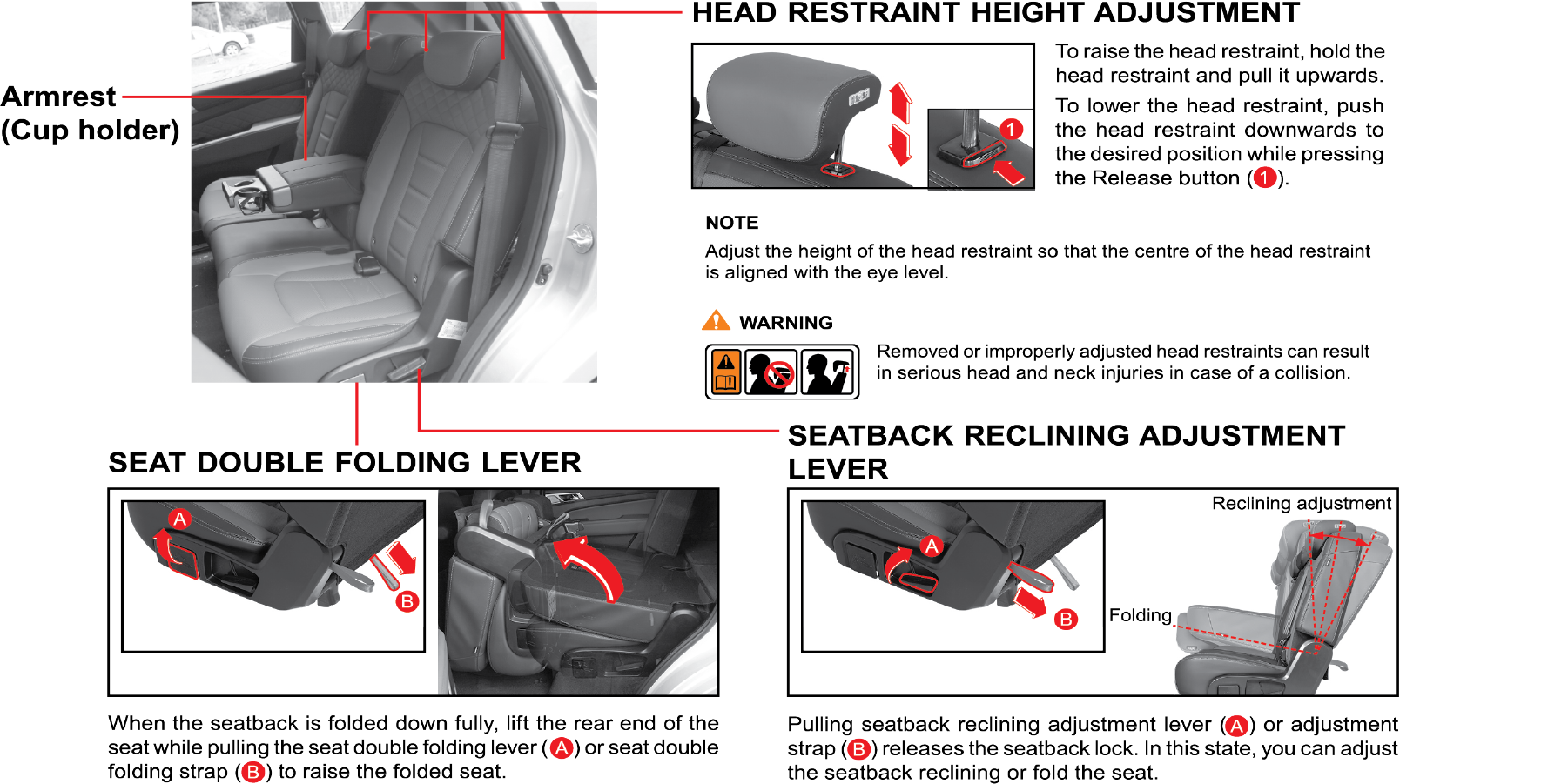
3.1 Seat
|
Configuration
|
Front seat |
|
 |
1. Front seat |
|
|
2. Sliding head restraint |
||
|
3. Driver seat ventilation switch |
||
|
4. Passenger seat ventilation switch |
||
|
5. Driver seat easy access* |
||
|
6. Seatback reclining adjustment |
||
|
7. Seat cushion tilt adjustment (driver seat) |
||
|
8. Seat height adjustment |
||
|
9. Seat slide adjustment |
||
|
Rear seat |
||
|
10. Second row seat |
||
|
11. Head restraint |
||
|
12. Armrest (cup holder) |
||
|
13. Seat double folding lever (strap) |
||
|
14. Seat back folding (reclining) lever (strap) |
||
|
15. Third row seat |
||
|
* if equipped |
3.2 Front Seat
3.2.1 Height Adjustment of Head Restraint
 |
To raise the head restraint, pull it up without pressing the release button. To lower the head restraint, press the release
button (1) on top of the seat back and push the head restraint down.
|
Adjust the height of the head restraint so that the centre of the head restraint is aligned with the eye level.
Do not apply excessive force to the head restraint during adjustment. It may get damaged.
Removed or improperly adjusted head restraints can result in serious head and neck injuries in case of a collision.
3.2.2 Forward and Backward Adjustment of Head Restraint
 |
The head restraint can be adjusted forward to three different positions by pulling the headrest forward. To push the head
restraint backward, pull it fully forward to the farthest position and release it. Adjust the head restraint so that it properly
supports the head and neck.
|
3.2.3 Removal/Installation of Headrest

|
Removal
|
||||||||||||
|
Installation
Do not adjust the driver’s seat when the vehicle is moving. Control of the vehicle can be lost.
|
3.2.4 Power Seat Adjustment (if equipped)
The advanced power seat provides 8-way electrical adjustments for the driver seat. It is equipped with electrically-operated
power slider, power recliner, power seat cushion and power height adjustment mechanisms.
The graphics on the switches guide you to the function it has been assigned.
 |
 |
 |
 |
| • | Make sure that your seat is completely locked after adjusting |
| • | Excessive operation of power seat may cause a problem for other electric devices. Stop operating the power seat immediately after getting the desired seat position |
| • | Be sure to operate the electric seat button one by one . Do not use two or more seat adjustment buttons simultaneously. It may damage the motor. |
| • | Folding the front seatback forward after sliding the front seat to the front-most position with the head restraint and seat cushion at their highest position can damage the sun visor and surrounding components. |
| • | The power seat can be activated with the ignition off. However, the extended use of the power seat switch with the engine off may wear down your battery. |
| • | Do not attempt to operate more than one seat adjustment switch at a time. It can damage the seat motor. Always use one adjustment switch after an adjustment is made. |
| • | Do not try to adjust the seat position using the switch if the seat does not move any further or touches any object. |
3.2.5 Manual Seat Adjustment (if equipped)
 |
To move the seat forward or backward, pull and hold the seat slide lever up and move the seat as desired. Then, release the
lever.
|
 |
To lower the seat cushion, push the lever down several times.
To raise the seat cushion, pull the lever up several times.
|
 |
To change the seat back angle, lean forward slightly and raise the lever. Then, lean back to the desired angle and release
the lever. After adjusting, make sure the lever is returned to its original position and the seat back is locked.
|
| • | Do not adjust the driver’s seat when the vehicle is moving. Control of the vehicle could be lost |
| • | Pay attention to the passenger in rear seat when adjusting the seat |
3.3 Second Row Seat
 |
3.3.1 Folding and Tumbling Second Row Seat

| • | To prevent the seat belt from being damaged, insert the seat belt into the webbing guide |
| • | Push down the head restraint fully |
Move the head restraint to the lowest position and raise the seat backrest right in front of it upright.
If any interference occurs when folding or unfolding the seat, the intervention area of the seat may be damaged.

| • | Fold the seat back (B) by pulling the seat back reclining adjustment lever (A) |
Make sure that the seat back is secured by pressing down the top of the folded seat back before tumbling the seat. If the
seat back is loose, it can interfere with the front seat and damage to the seat may occur.
The seat back can be folded down fully. Make sure that any body part of the occupants is not caught by the folded seat back.

| • | Lift the rear end of the seat (D) while pulling the seat folding lever (C) to raise the folded seat |
| • | To return the seat to its original condition the procedure is the reverse of folding |
| • | Do not sit on the folded or double folded seat. You cannot be protected by the seat belt or proper restraint system and could get seriously injured in the event of an accident |
| • | Do not drive the vehicle or load any cargo while the Second row seat is in the vertical position |
Unfold the seat in the reverse order of folding. Make sure that the seat is securely locked. If the seat is not locked, the
seat may fold forward.
|
|
Do not drive the vehicle or load any cargo while the Second row seat is in the vertical position. |
|
|
It may cause the third row seat occupant to suffer injury or cargo to be damaged. |
|
|
Secure the Second row seat in the correct position when an occupant is seated on the third row seat. |
|
|
When returning the Second row seat to its original position, be careful not to hit the feet and leg of the passenger in the
third row seat.
|
|
|
Do not operate the Second row seat while the third row seat occupant is raising his/her feet on the seat backrest. The occupant
may be injured due to the Second row seat.
|
3.4 Third Row Seat
3.4.1 Head Restraint Adjustment
 |
 |
To raise the head restraint, pull it up without pressing the release button. To lower the head restraint, press the release
button (1) on top of seat back and push the head restraint down.
Removed or improperly adjusted head restraints can result in serious head and neck injuries in case of a collision.
3.4.2 Seat Folding (Making a Luggage Compartment)

| • | Position the headrest to the lowest level |
| • | Pull up the folding loop of the third row seat, and fold the seat back forward |
| • | Fold the seat back of the third row seat to make the luggage compartment |
3.4.3 Luggage Board
You can adjust the height of the folded seat and floor using the luggage board. To adjust the height of the folded seat and
floor, lift the luggage board up and insert it into the left and right grooves.

| • | Fold down the third row seats. (refer to “Folding the third row seat” section) |
| • | Fold down the second row seats. (refer to “Folding the second row seat” section) |
| • | Lock the seat back of second row seats by pressing the upper portion of it |
| • | Make a bed |
| • | When you put the luggage on the folded seat, make sure that the luggage is placed firmly enough to avoid being shaken while driving. A shaky or improperly fixed luggage may injure the driver or passenger. Besides, ensure that the luggage does not obstruct the field of the rearview |
| • | Do not sit on the folded seat because the seat belt and other safety devices would not be able to protect you. It may cause serious injury in case of accident |
3.5 Front Seat Ventilation Switch (if equipped)

Press the (B) part of the seat ventilation switch with engine running to select one of 4 levels in the following sequence:
OFF → level 3 → level 2 → level 1 → OFF. The indicator corresponding to the selected level is illuminated in yellow.
Press the (A) part of the seat ventilation switch with engine running to select one of 4 levels in the following sequence:
OFF → level 3 → level 2 → level 1 → OFF. The indicator corresponding to the selected level is illuminated in green.
Electric fan for ventilated seat
When the seat ventilation switch is operated, 4 ventilation fans run to reduce the discomfort resulted from the contact with
the seat in hot weather.

| • | The ventilated seat uses the interior air for ventilation. Make sure that it is used together with the air conditioner |
| • | The ventilated seat is not a cooling/heating seat which blows out cold air from it |
| • | Don’t put your hand in the bottom of the cushion when the ventilated seat is in operation. Otherwise, the running ventilation fan may cause you to be frightened or injured |
| • | The battery can be discharged if the seat ventilation switch and current consumers are used with IGN ON (engine off) |
| • | Power seats can be operated even when the ignition switch is turned to the "OFF" position. However, to prevent battery discharge, operate your seats when the engine is running |
| • | Do not use two or more seat adjustment buttons simultaneously. It can damage the motor. Be sure to operate the electric seat button one by one |
| • | When cleaning leather seats, never use oil-based solvents such as benzene, alcohol, gasoline, or thinner. It can cause discolouration and dull the surface of the seats |
| • | Do not forcibly operate any power adjustment switch if the seat comes in contact with other object and cannot be adjusted anymore |
| • | If the power seats are not operational, the seats should be checked and fixed before any driving |
| • | Do not leave children unattended in parked vehicles. This can cause unexpected accident |
| • | You can be hurt by the edges of the mechanism of the seat when trying to get the small objects (cigarette lighters, coins, credit cards) under the seat or caught between the seat and the centre console. Wear protective gloves to prevent injury |
| • | Never try to adjust the seat while the vehicle is moving |
| • | Unexpected movement of the seat or seat back can cause loss of control |
| • | Take care not to bother the passenger behind you when adjusting the seat position |
| • | For lap belt-Sit upright in the centre of the seat and wear the seat belt around your hip and pelvic bones |
| • | Do not place any objects in the path of seat back movement. Any obstruction in this path prevents the seat back from being locked, causing severe injuries or death during a collision |
| • | Always raise the seat back to the proper upright position before driving |
| • | Never drive the vehicle with the seat folded. In a collision, there is a risk of serious injury or even death in the absence of the primary restraint provided by the seat belt. |
| • | To avoid unexpected accidents including severe injuries and death, sit in the position so that the distance between the steering wheel and your chest is at least 25 cm, as long as you are comfortable with driving |
| • | Additional cushion between you and the seat cushion reduces the frictional force and could make you slide under the seat belt. This could result in serious injury or death |
| • | Do not insert your hands under the seat or in the path of the seat movement when adjusting the seat. Your hands or fingers could get trapped between the seat and the frame |
| • | Do not ride with the seat back reclined too much. You could slide under the seat belt in a collision, which could result in severe injury or death. Also, you cannot be protected by the seat belt and the belt can strangle you or even cut into your stomach. Therefore, sit up straight in your seat by keeping your seat back upright while driving |
| • | When returning the seat back to the upright position, hold the seat back with your one hand and pull the release lever with the other hand. The more the seat back is reclined, the greater the restoring force of the seat back is. If you do not hold the seat back while adjusting the seat back , you could be injured by the restoring force |
3.6 Seat Belt
3.6.1 Configuration
To protect you and your passengers in the event of an accident, it is highly recommended that the seat belts should be used
by all occupants inside of your vehicle.

Driver seat belt warning lamp
If the driver turns on the ignition switch without fastening the seat belt, this warning lamp will flash for about 6 sec.
along with the warning buzzer. If you fasten the seat belt, the warning buzzer will stop sounding but the warning lamp will
keep flashing for the remaining time (total 6 sec.)
Buzzer will continue if seat belt are not fastened.
3.6.2 Seat Belt Pretensioner
In the event of a crash being detected, the belt pretensioner locks the seat belt by drawing back the seat belts on the driver’s
and passenger’s torso and pelvis to prevent the driver and passenger being thrown forward. The seat belt pretensioner combined
with the seat belt and airbag further increases safety.
In case of side impact collisions, front air bags are not inflated, but seat belt pretensioners located in the same position
with impact direction will be deployed together with front seat side air bag
Deployed seat belt pretensioners cannot be deployed again. Have the deployed seat belt pretensioners replaced by an Authorised
dealer.

Operation of pretensioner
When a severe frontal impact occurs, seat belt pretensioners pull back the seat belts immediately to restrain the occupants
to their seats.

Operation of load limiter
After frontal collision, the load limiter releases the seat belt to prevent the occupant from being injured due to belt force.
Fastening the seat belt
Even if seat belts is not worn, the air bag will be deployed in case of impact collision triggered. In addition, airbags can
protect occupants when the occupants are wearing their seat belts. Airbags may cause injuries to occupants if they do not
wear or inappropriately use their seat belts.
| • | Before driving, all occupants should fasten their seat belts. If not, the occupants can seriously be injured in a collision or sudden manoeuvring of the vehicle |
| • | Sometimes you may have to apply strong force to pull the webbing out of the retract |
| • | Each seat belt should be used by only one occupant at a time |
| • | Seat belts and airbag’s can significantly minimise possible injury to occupants. But they cannot perfectly protect occupants from fatal collisions or injury |
| • | Modifications and improper maintenance for the safety systems could cause serious injury. The safety systems including seat belts should be checked and repaired by only a Mahindra Dealer or Mahindra Authorised Service centre |
| • | An infant or small child should always be restrained in an infant or child restraint |
Restraint of pregnant women

| • | Expectant mothers must position the lap portion of the belt as low as possible below the rounding of the abdomen to avoid the belt pushing the foetus when a collision or sudden braking occurs |
| • | Driving while pregnant can be very dangerous, so avoid driving if possible |
| • | Consult your doctor about seat belt position during pregnancy |
| • | The risk of injury in the event of an accident is increased for both the pregnant woman and unborn child if the seat belt is not worn |
3.7 How to Fasten the Three Point Seat Belt

| • | Pull out the latch plate from the retractor. If the seat belt is locked when being pulled out, rewind it completely in the retractor, then pull it out to the desired length |
Sometimes you may have to apply strong force for 2 to 3 sec. to pull the webbing out of the retract.

| • | Position the shoulder belt across the body and the lap belt as low as possible across the hips. Insert the latch plate into the buckle until it clicks |
| • | Adjust the seat belt height as needed |
Sit back in the seat with the seat back in an upright position and wear the seat belt.
Make sure that the seat belt webbing is not twisted

| • | Pull the latch plate to make sure it is securely locked. A slack belt will greatly reduce the protection afforded to the wearer |
| • | To unfasten the seat belt, press the red button on the buckle |
Improperly worn seat belts could cause serious injury or death.
| • | Put the lap belt as low as possible across the hips. Do not put it across the waist. In an accident, the belt may apply pressure to your abdomen. This may cause internal injuries |
| • | The shoulder belt should be positioned midway over the shoulder, never across the neck |
3.8 Front Seat Belt

To adjust the height of the shoulder belt anchorage, raise or lower the seat belt holder while pressing the top of the seat
belt height adjuster (A).
Release it at the desired position.
| • | Adjust the seat belt height before driving |
| • | Shoulder belt should be positioned midway over the shoulder, never across the neck |
| • | Insert the metal latch plate into the buckle until it clicks |
| • | To unfasten the seat belt, press the button (B) on the buckle |
3.9 Second Row Seat Belt
3.9.1 Stowing the Buckle
 |
When you are not using the rear seat belt, insert the buckle in the buckle storage like shown in the picture.
|
3.9.2 Stowing Rear Seat Belt
 |
If you are not using the rear seat belt or trying to fold the rear seat, insert the seat belt webbing into the webbing guide
on the side wall.
|
To use the seat belt, remove the seat belt from the guide before pulling out the webbing from the retractor. Pulling out the
webbing from the retractor without removing it from the webbing guide can cause damage to the webbing guide or the belt itself.
3.10 How to Fasten the Seat Belts (2-Point) in Second Row Seat
 |
|
Put the lap belt as low as possible across the hips. Do not put it across waist. In an accident, the belt may apply pressure
to your abdomen. This may cause serious internal injuries.

To adjust length, hold the metal latch plate at a right angle to the belt and pull the belt. To shorten, pull the free end
of the belt away from the latch plate, then pull the belt clip to take up the slack.
| • | Insert the metal latch plate into the buckle until it clicks. Position the belt as low as possible across your hips, not across
your abdomen |
| • | If the belt is too tight or slack on your hips, readjust the belt |
| • | To unfasten the seat belt, press the red button on the buckle |
3.11 Child Restraints and Pregnant Woman
3.11.1 Pregnant Women
We recommend that pregnant women use the seat belts throughout their pregnancy. Keeping the mother safe is the best way to
keep the baby safe.
| • | Pregnant women should wear 3-point seat belt whenever possible according to the professional recommendations by her doctor |
| • | Pregnant women should wear the lap portion of the belt across the thighs and as snugly and low as possible |
3.11.2 Child Restraints
When transporting infants or small children, an appropriate child restraint system should always be used. The child restraint
system should be appropriate for your child’s weight and height and properly fit the car’s seat. Accident statistics indicate
that children are safer when properly restrained in the rear seat rather than in the front seat.
3.11.3 Securing Methods of Child Restraint System
Child restraint systems are designed to be secured in vehicle seats by seat belts or the latch system (ISOFIX seat - if equipped).
| • | Infants and tiny children should always be restrained in an infant or child restraint |
| • | Never instal a rear-facing child restraint in the front seat with front passenger airbag |
| • | A child in a rear-facing child restraint installed in the front seat can be seriously injured if the front passenger airbag inflates. Secure a rear-facing child restraint in the rear seat |
| • | A front-facing child restraint should be secured in the rear seat whenever possible. If installed in the front passenger seat, adjust the seat as far back as it will go |
| • | When installing a child restraint system, follow the instructions provided by the manufacturer |
| • | When your child restraint is not in use, secure it in the vehicle with the seat belt or remove it from the vehicle |
| • | In a collision an unrestrained child, even a tiny baby, can become a missile inside the vehicle. The force required to hold even an infant on your lap can become so great that you could not hold the child, no matter how strong you are |
| • | Do not allow a child in the cargo areas while the vehicle is moving |
| • | If the shoulder belt contacts the face or neck, move the child closer to the centre of the vehicle. Never allow a child to put the shoulder belt under an arm or behind their back |
| • | Please note that the three-point seat belt is designed for a person who is taller than 140 cm |
3.11.4 Infant and Child Safety
Child Seat
Children that are too small to use the seat belts must be properly secured in a child restraint system.
| • | Never place a rear-facing child restraint in the front passenger seat with front passenger airbag, because of the danger that an inflating passenger airbag could impact the rear-facing child restraint and kill the child |
| • | Use only the qualified child restraint systems. Follow the manufacturer’s instructions for installation and use of the child restraint systems |
| • | Do not carry your child on your lap while driving. You cannot resist against the impact pressure in an accident. The child could be crushed between you and the parts of vehicle |
| • | Remember that a child restraint seat left in a concealed vehicle can cause it to be very hot. Check the seating surface before putting your child in the child restraint |
| • | When your child restraint is not in use, remove it from the vehicle or keep it secured with a seat belt to prevent it from being thrown forward in case of a sudden stop or an accident |
| • | When installing a child restraint, do not let the seat belts come across the child’s neck |
Table of Vehicle Handbook Information on Child Restraint Systems Installation Suitability for Various Seating Positions
|
Rear-facing child seat
 |
Forward-facing child seat
 |
|
Booster seat
 |
 |
|
Mass group |
Restraint device figure |
Front seat |
Second row seat centre |
Second row seat out board |
Mounting method of vehicle |
|
O ~ up to 10 kg (0 ~ 9 month) |
Rear facing child seat |
X |
X |
U |
3-point belt rear-facing |
|
O+ ~ up to 13 kg (0 ~ 2 years) |
Rear facing child seat |
X |
X |
U |
3-point belt rear-facing |
|
I ~ 9 to 18 kg (9 month ~ 4 years) |
Forward facing child seat |
X |
X |
U |
2 (or) 3-point |
|
II ~ 15 to 25 kg (4 year ~ 12 years) |
Booster seat |
X |
X |
U |
2 (or) 3-point |
|
II ~ 15 to 25 kg (4 year ~ 12 years) |
Booster seat |
X |
X |
U |
2 (or) 3-point |
|
U: Suitable for “universal” category restraints approved for use in the mass group.
UF: Suitable for forward-facing “universal” category restraints approved for use in the mass group.
L: Suitable for particular child restraints given on attached list. These restraints may be of the “semi-universal” categories.
X: Seat position not suitable for children in the mass group.
|
3.11.5 Illustration of CRS Secured by the Seat belt
Front-facing Child Seat

Secure the child restraint with a seat belt as shown in the figure.
When installing a child restraint system, follow the instructions provided by the manufacturer.
Do not use the car seat unless the following are met. The child seat may not perform as intended, which may result in a serious
injury.

| • | Make sure that the buckle of the seat belt is securely engaged |
| • | Make sure that the seat belt is not loose or twisted |
| • | Make sure that the base does not move due to excessive play in all directions |
| • | You can’t adjust the angle of the backrest with the child seat installed. If you’re trying to do so, the seat belt will be slack, which incurs danger. Always adjust the angle of the backrest before installing the child seat |
Rear-facing Child Seat

Secure the child restraint with a seat belt as shown in the figure.
Never instal a rear facing child restraint on the front seat without ensuring that the front airbag is deactivated. Mahindra
recommends that a child restraint to be installed on the rear seat.
When installing a child restraint, adjust the seatback angle as desired.
Do not use the child seat unless the followings are met. The child seat may not perform as intended, which may result in a
serious injury.

| • | Make sure that the buckle of the seat belt is securely engaged |
| • | Make sure that the seat belt is not loose or twisted |
| • | Check if the angle of the backrest is set to 4 stage |
| • | Make sure that the base does not move due to excessive play in all directions |
| • | Make sure that the seat belt is routed through the rear-facing belt path and buckled up |
3.11.6 Securing a Child Restraint System with “ISOFIX” System
How to use the ISOFIX Lower Latch Anchor

| • | The ISOFIX lower latch anchors are located in the left and right outboard rear seating positions. Their locations (1) are shown in the illustration |
| • | Insert the child restraint attachments into the ISOFIX lower latch anchors until it clicks |
| • | Do not use the seat belt for installing the ISOFIX child restraint |
| • | There is no ISOFIX lower latch anchor provided for the centre rear seating position |
ISOFIX system is a standardised method of fitting child seats that eliminates the need to use the standard adult seatbelt
to secure the seat in the vehicle. This enables a much more secure and positive location with the added benefit of easier
and quicker installation.
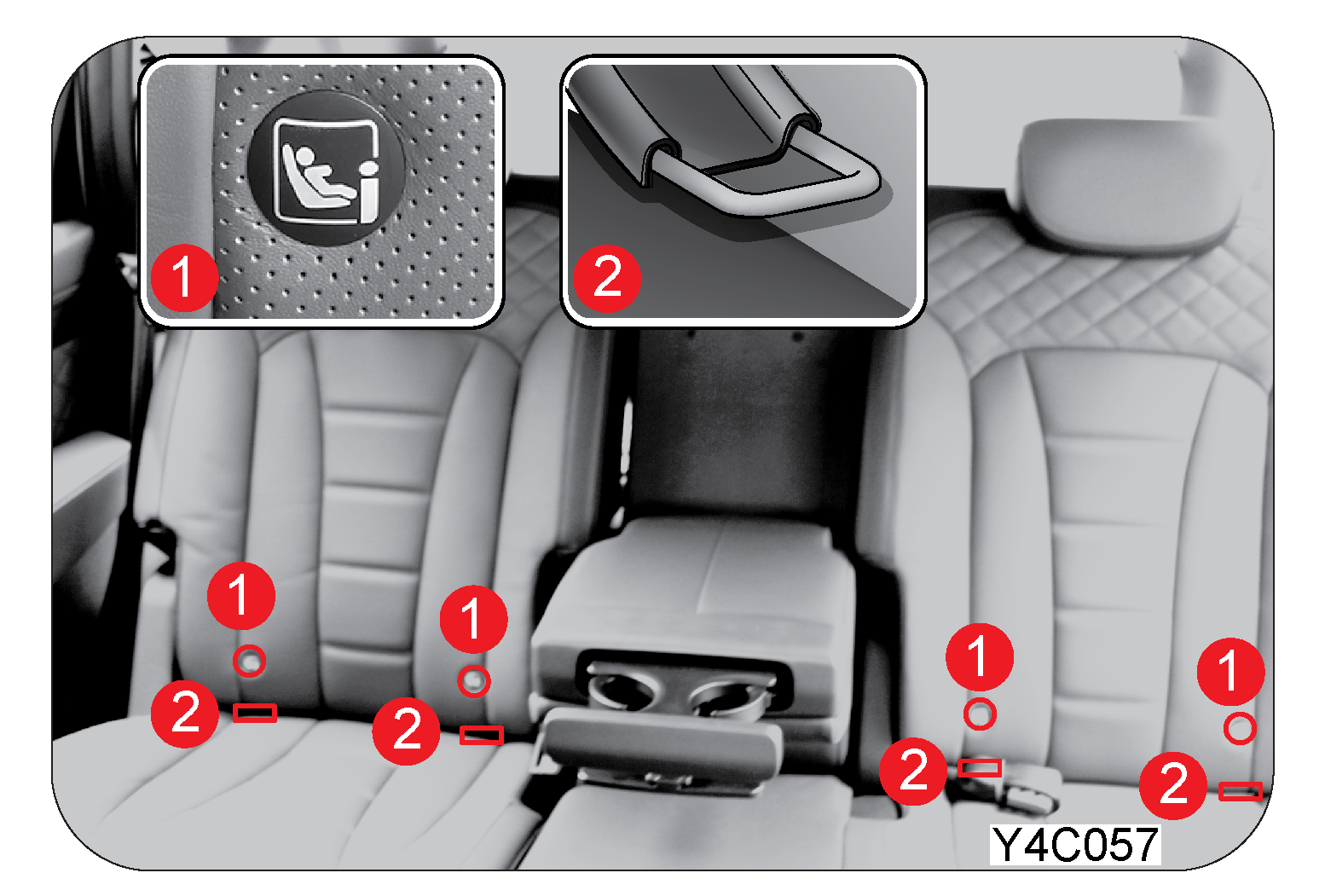
|
1 |
ISOFIX mark |
|
2 |
Latch anchor |
| • | When using the “ISOFIX” lower latch system, all unused vehicle rear seat belt metal latch plates or tabs must be latched securely in their seat belt buckles and the seat belt webbing must be retracted behind the child restraint to prevent the child from reaching and taking hold of unretracted seat belts. Unlatched metal latch plates or tabs may allow the child to reach the unretracted seat belts which may result in strangulation and a serious injury or death to the child in the child restraint |
| • | Child restraint anchorages are designed to withstand only those loads imposed by correctly-fitted child restraints. Under no circumstances are they to be used for adult seat belts, harnesses or for attaching other items or equipment to the vehicle |
How to use the Rear Anchor
| • | There are two rear anchors on the floor under the 3rd row seat. (7-seater)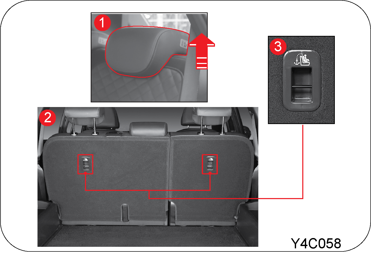 |
| 1. | Remove the headrest from the second row seat |
| 2. | Place the child restraint on the second row seat |
| 3. | Connect the tether connector in child restraint to the rear anchor. Securely tighten the child restraint by adjusting the webbing of the tether connector |
Cautions for ISOFIX Seat
| • | The rear anchor is the supplemental device to secure the child restraint system after engaging it by the lower latches. Therefore, do not secure the child restraint system only with the seat back anchors. The increased load may cause the hooks or anchors to break, causing serious injury or death |
| • | If a child restraint is not properly secured to the vehicle and a child is not properly restrained in the child restraint, the child could be seriously injured or killed in a collision. Always follow the instructions provided by the manufacturer for installation |
| • | Make sure the latches of the child restraint system are latched to the lower latches. In this case, you can hear the “click” sound |
| • | Incorrectly installed child restraint system may cause an unexpected personal injury |
| • | Child restraint anchorages are designed to withstand only those loads imposed by correctly fitted child restraints |
| • | The tether strap may not work properly if attached somewhere other than the correct rear anchor |
| • | Rock the child restraint to check if it is securely installed. Refer to instructions provided by the manufacturer of the child restraint |
| • | Do not instal the child restraint if it hinders the operations of front seat |
| • | All the procedures described here are to assist you in understanding the child restraint system. Use this as a reference only. When you install a child restraint to your vehicle, observe instructions for installation in the manual provided by the manufacturer |
Table of Vehicle Handbook Information on ISOFIX Child Restraint Systems Installation Suitability for Various ISOFIX Positions
|
Mass group |
Size Class |
Fixture |
Vehicle ISOFIX Positions |
||
|
Front Passenger |
2nd seat row centre |
2nd seat row out board |
|||
|
Carrycot |
F |
ISO/L1 |
X |
X |
X |
|
G |
ISO/L2 |
X |
X |
X |
|
|
Group 0 up to 10kg |
E |
ISO/R1 |
X |
X |
IL |
|
Group 0+ up to 13kg |
E |
ISO/R1 |
X |
X |
IL |
|
D |
ISO/R2 |
X |
X |
IL |
|
|
C |
ISO/R3 |
X |
X |
IL |
|
|
Group I 9 to 18kg |
D |
ISO/R2 |
X |
X |
IL |
|
C |
ISO/R3 |
X |
X |
IL |
|
|
B |
ISO/F2 |
X |
X |
IUF |
|
|
B1 |
ISO/F2X |
X |
X |
IUF |
|
|
A |
ISO/F3 |
X |
X |
IUF |
|
Key of letters be inserted in the above table
IUF: Suitable for ISOFIX forward child restraint systems of universal category approved for use in this mass group.
IL: Suitable for particular ISOFIX child restraint systems (CRS) given in attached list. These ISOFIX CRS are those of the
“specific vehicle”, “restricted” or “semi-universal” categories.
X: ISOFIX position not suitable ISOFIX child restraint systems in this mass group and/or this size class.
List of suitable universal Child Restraint Systems (CRS)
Please read carefully the installation manual of child restraint system.
|
Mass group |
Child Restraint |
Features |
|
|
0 |
˂ 10 kg |
— |
— |
|
0+ |
˂ 13 kg |
Maxi Cosi CabrioFix |
Belted Rearward facing |
|
I |
9 to 18 kg |
Römer King II LS |
Belted Forward facing |
|
II |
15 to 25 kg |
Römer KidFix XP |
Belted Forward facing |
|
III |
22 to 36 kg |
Römer KidFix XP |
Belted Forward facing |
List of suitable ISOFIX Child Restraint Systems (CRS)
Please read carefully the installation manual of child restraint system.
|
Mass group |
Child Restraint |
Features |
|
|
0 |
˂ 10 kg |
— |
— |
|
0+ |
˂ 13 kg |
Maxi Cosi CabrioFix & FamilyFix |
ISOFIX & Support Leg Rearward facing |
|
I |
9 to 18 kg |
Römer Duo+ |
ISOFIX & Top Tether Forward facing |
|
II |
15 to 25 kg |
Römer KidFix XP |
ISOFIX & Belt Forward facing |
|
III |
22 to 36 kg |
Römer KidFix XP |
ISOFIX & Belt Forward facing |
3.11.7 Warning for Child Restraint
| • | Use only the officially approved child restraint Mahindra is not responsible for the personal injury and property damage due to the defect of child restraint
|
| • | Use only the child restraint with proper type and size for your baby |
| • | Use only the child restraint at proper location |
| • | Child restraint has 5 categories based on the weight as below
|
| • | Group 0 & 0+ Rear facing child restraint fitted on the rear seat
|
| • | Group I Forward facing child restraint fitted on the rear seat
|
| • | Group II & III Booster seat fitted on the rear seat with seat belt fastened. Always follow the installation and use instructions provided
by the manufacturer of the booster seat
|
3.11.8 Warnings for Seat Belt
| • | Always put on your shoulder belt over the shoulder and across the chest. Do not put the shoulder belt across your neck |
| • | Put the lap belt as low as possible across the hips. Do not put it across the waist. In an accident, the belt may apply pressure to your abdomen |
| • | Do not wear the shoulder belt under the arm. It increases the danger of sliding out of the belt and can cause serious injury or even death. The belt may also tighten the chest which is not as strong as the shoulders. This may also result in serious internal injuries |
| • | Do not lock the seat belt with a clip or a clamp. If the seat belt is too loose, it may not protect your body from injury or death in an accident |
| • | Before driving, all occupants should wear the seat belts. Otherwise, occupants could be seriously injured in collisions or sudden manoeuvers. In many countries, there are regulations regarding the use of the seat belts. Please observe local laws and regulations |
| • | Do not buckle up two or more persons with one seat belt |
| • | Do not wear the seat belt over any hard or breakable objects in pockets or on clothes |
| • | An infant and tiny child must be restrained in a child restraint system. Note that the three-point seat belt is designed for a person who is taller than 140 cm |
| • | Periodically check that the seat belt and its components work properly. A damaged seat belt can cause serious injuries. Repair or replace the damaged seat belt immediately at a Mahindra Dealer or Mahindra Authorised Service centre |
| • | The warning light comes on whenever the ignition is switched on. The light goes out when the driver’s seat belt is securely fastened. If the light does not go off after fastening the seat belt, it means that there is a malfunction in the system. Have the seat belt system checked by a Mahindra Dealer or Mahindra Authorised Service centre |
| • | Additional devices or accessories on the seat belt may result in improper operation. Do not add any adjusting devices which restrict the seat belt operation |
| • | Periodically inspect all parts of the belt and have the damaged parts replaced. The belt that has been overstretched in an accident must be replaced with a new one. Mahindra recommends replacing all component parts of the seat belt after a collision. No replacement is required after a minor collision if a Mahindra Dealer or Mahindra Authorised Service centre finds that no damage has occurred and everything is in proper working order. The seat belt components that were not used during a collision must also be inspected and replaced if they show signs of damage or faulty operation |
| • | Replace the entire seat belt assembly after a severe impact even if the damage is not obvious |
| • | Never modify the seat belt |
| • | Always keep the seat belts clean and dry. Care should be taken to avoid contamination of the webbing with polishes, oil and chemicals, and particularly battery acid. Use mild soap and water for cleaning. The seat belt must be replaced if webbing becomes frayed, contaminated or damaged |
| • | Adjust the seat properly before wearing the seat belt |
| • | Sit back in the seat with the seat back in an upright position and wear the seat belt. If the seat belt is positioned too high or fastened too loose, it may not protect your body from an injury or death in the event of a collision |
| • | Do not recline the seat back more than needed for comfort while vehicle is in use. Seat belt is the most effective when the passenger sits back and straight up in the seat. If the seat back is reclined too much, then the risks of sliding under the lap belt and getting injured are increased |
| • | If the latch plate is inserted into a wrong buckle, the belt may exert pressure on your abdomen instead of your pelvis. This may cause serious internal injury |
| • | If the seat belt is twisted, there will not be enough contact of the belt to spread the impact pressure |
| • | Make sure that the latch plate is securely locked |
| • | When pregnant women use the seat belt, consult with a doctor for specific recommendations |
| • | Keep the buckle clean |
| • | Seat belts are designed to bear upon the bony structure of the body, and should be worn low across the front of the pelvis or the hips, chest and shoulders, as applicable; wearing the lap section of the belt across the abdominal area must be avoided |
| • | Seat belts should be adjusted as firmly as possible, consistent with comfort, to provide the protection for which they have been designed. A slack belt will greatly reduce the protection afforded to the wearer |
| • | Belts should not be worn with straps twisted |
| • | Each belt assembly must only be used by one occupant; it is dangerous to put a belt around a child being carried on the occupant’s lap |
| • | No modifications or additions should be made by the user which will either prevent the seat belt adjusting devices from operating to remove slack, or prevent the seat belt assembly from being adjusted to remove slack |
| • | If the seat belt cannot be pulled out of the retractor, firmly pull the belt and release it. You will then be able to smoothly pull the belt out of the retractor |
| • | Never unbuckle the seat belt while travelling. Careless driving actions, such as fastening/releasing the seat belt repeatedly, may result in serious injury |
| • | Make sure that the seat belt does not go around any solid body or fragile objects |
| • | Keep the buckle clean. Foreign materials caught inside the buckle can prevent the seat belt latch plate from being locked |
3.12 Airbag
3.12.1 Configuration

|
1 |
Driver Airbag |
4 |
Rear Side Airbag |
|
2 |
Front Side Airbag |
5 |
Curtain Airbag |
|
3 |
Passenger Airbag |

|
A |
Knee Airbag |
Passenger Airbag ON/OFF Switch (if equipped)

The front passenger airbag is disabled (not inflatable) when placing the passenger airbag ON/OFF switch to “OFF” position.
This switch is located on the left side of the instrument panel, and you can see it when opening the front passenger door.
Press and turn this switch to operate.
“OFF” position: disabled (not inflatable)
“ON” position: enabled (inflatable)
3.12.2 Airbag Crash Sensor

| 1. | Airbag crash sensor |
| 2. | Front impact sensor (G-sensor type) |
| 3. | Side impact sensor (Pressure sensor type) |
| 4. | Side impact sensor (G-sensor type) |
3.12.3 Airbag Warning Label

The airbag warning label is located on both sides of the passenger side sun visor reminding the occupant to understand the
dangerousness of the airbag. Read and follow Instructions and safety information before driving.
NEVER use a rearward facing child restraint on a seat protected by an ACTIVE AIRBAG in front of it, DEATH or SERIOUS INJURY
to the CHILD can occur
3.12.4 Airbag Warning Lamp
The airbag warning lamp comes on when the ignition switch is turned ON, and goes off if the system is OK.

If this lamp stays on, it means that there is a fault in the airbag or seat belt pretensioner system. Have the system checked
immediately at a Mahindra Dealer or Mahindra Authorised Service Centre.
What is an airbag?
An airbag is a safety device which is deployed in the event of a strong front (front airbag) or side collision (curtain airbag)
to reduce the risk of severe personal injury.
Along with seat belts fastened, the airbags work to provide improved protection for the occupants. If an airbag is deployed
with the seat belt improperly fastened or unfastened, the deployment of airbag can lead to serious injury. For this reason,
airbags are also called supplemental restraint system.
SRS: Supplemental Restraint System
| • | The airbag system serves as a supplement to the seat belt. Make sure you and your passengers always wear seat belts properly, even if airbag’s are installed in the vehicle |
| • | Depending on the severity or the angle of impact, the airbag may not deploy |
| • | The driver’s and front passenger’s airbag’s simultaneously deploy |
| • | Extreme Hazard! Do not use a rearward facing child restraint on a seat protected by an airbag in front of it |
| • | The airbag warning label is located on the sun visor reminding the occupant to understand the importance of the airbag |
3.12.5 Driver Airbag
The driver airbag is located in the centre of the steering wheel. This airbag protects the driver's head in a front collision.
The driver should sit in the position so that your body is away from the steering wheel as far as possible while you are comfortable
with driving
Do not put any object or attach stickers on the driver airbag cover (steering wheel cover)
3.12.6 Driver Knee Airbag (if equipped)

Located on the dashboard under the steering wheel, the driver's knee airbag can help protect the driver by inflating simultaneously
with the front airbag in head-on collision.
3.12.7 Passenger Airbag

The passenger airbag is located in the front dashboard. This airbag protects the front passenger's head in a front collision.
| • | The rear seats are safer for children |
| • | Do not instal the child seat on the front seat |
| • | Sit as far as possible from the airbag |
| • | Use the seat belt and child restraint system |
3.12.8 Front Seat Side Airbag (if equipped)

The front seat side airbag is mounted in the side of the driver seat back and passenger seat back. This airbag is deployed
in a side collision which meets the airbag deployment conditions to protect the occupants in the front seats.
| • | The airbag operation may vary depending on the impact level and collision angle |
| • | Do not use seat covers or hang clothes/accessories on the seats with side airbag |
3.12.9 Second Row Seat Side Airbag (if equipped)
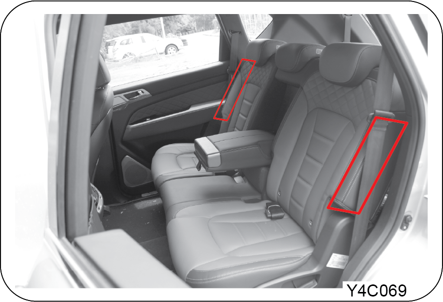
The second row seat side airbag is mounted in the side of the rear seat back. This airbag is deployed in a side collision
which meets the airbag deployment conditions to protect the occupants in the rear seats.
3.12.10 Curtain Airbag (if equipped)

The curtain airbag is mounted inside the area above the front/rear doors, which meets the bottom of the roof on both sides.
This airbag is deployed in a side collision which meets the airbag deployment conditions to protect the occupants in the front
and rear seats.
| • | Do not apply impact on the area where the collision detection sensors for curtain airbag and side airbag are installed. The airbag may be deployed accidentally |
| • | Do not slam the door as the curtain airbag may be deployed unexpectedly |
| • | The curtain airbag’s and side airbag’s are deployed at the same time during a side collision. Those airbag’s on each side is activated independently of each other |
Front Airbag Operation (Driver and Passenger Side)
The airbag inflates when:
| • | In response to a severe frontal impact, the driver’s and front passenger’s airbag deploy at the same time to supplement the seat belts to prevent or reduce any personal injuries |
The airbag can inflate when:
| • | Underbody impact from the road surface; impact against the curb at a very high speed; dropping impact onto the road surface with a large angle |
The airbag does not inflate when:
| • | Rollover, side impact or rear impact |
| • | If the severity of impact to the vehicle is not significant |
The airbag seldom inflates when:
| • | Oblique impact, rollover |
| • | Weak impact in which the sensor is unable to detect (under the inflation requirements) |
| • | Impact against narrow objects such as a utility pole or a tree |
| • | The vehicle falls into a drainage or a puddle |
| • | The front of the vehicle crashes into a high impact point vehicle such as a truck |
| • | Impact on the hood by falling stones |
| • | The airbag warning lamp is on |
| • | Moderate or severe impact to the middle of the vehicle body’s side structure. In that case, only the side airbag will deploy |
Curtain Airbag and Side Airbag Operation
The airbag inflates when:
| • | A moderate to severe impact to the middle of the vehicle body’s side structure |
The airbag can inflate when:
| • | Vehicle rolls onto its side and causes a severe side impact |
The airbag does not inflate when:
| • | Frontal collision while vehicle stops or is moving at a low speed |
| • | Rear end collision |
| • | If the severity of impact to the vehicle is not significant |
The airbag seldom inflates when:
| • | Oblique impact (diagonal direction) |
| • | Frontal impact or rear impact |
| • | Rollover but without a severe impact |
| • | The airbag warning lamp is on |
3.13 Airbag Non-inflation Conditions
3.13.1 Low Speed Collision

In collisions, the seat belts are sufficient to protect the vehicle occupants and the airbag’s may not deploy. In some cases,
deploying airbag in low-speed collisions can cause a secondary impact to the occupants (light abrasions, cuts, burns, etc.),
or loss of vehicle control.
3.13.2 Rear Collision

Airbags may not inflate in rear collisions, because occupants are moved backward by the force of the impact. In this case,
the airbag’s do not provide proper protection.
3.13.3 Side Collision

Front airbag’s may not inflate in side impact collision, because occupants move to the direction of the collision, and thus
front airbag deployment does not provide proper protection.
However, side or curtain airbag (if equipped) may inflate depending on the intensity, vehicle speed and angles of impact.
3.13.4 Angled Collision

In a slant impact or collision, the force delivered will be relatively weaker than that of frontal collision. So, the airbag’s
may not inflate.
3.13.5 Under-Ride

At the moment of an accident, drivers brake heavily with reflex. In such heavy braking, the front portion of the vehicle is
lowered by the force of the braking and the vehicle can go under a vehicle with a higher ground clearance. airbag’s may not
inflate in this situation because impacts may not be delivered or may be delivered with less intensity.
3.13.6 Rollover
Airbags may not inflate in rollover accidents because airbag deployment would not provide proper protection to the occupants.
However, side airbag may inflate when the vehicle is rolled over by a side impact collision, if the vehicle is equipped with
side airbag and/or curtain airbag.
3.13.7 Collision with Narrow Object

Airbags may not inflate if the vehicle collides with objects such as utility poles or trees, where the point of impact is
concentrated to one area and the full force of the impact is not delivered to the sensors.
3.13.8 Secondary Injury Due to Airbag Deployment

If the airbag control module detects the impact during an accident, it transmits the signal to deploy the airbag. This signal
triggers the explosion of the powder, which is included in the airbag module, and the airbag deploys in a very short time
to protect the occupants. When the airbag inflates, there will be heavy noise, glare and smoke. You could suffer secondary
injuries caused by inflated airbag such as an abrasion, a bruise, a burn or injury by broken glasses.
3.14 Warning and Caution
| • | All necessary driver’s seat adjustments should be made before any driving |
| • | Make sure that your seat is completely locked after adjusting |
| • | Any object that might damage the seat should not be placed on the seat |
| • | Removed or improperly adjusted head restraints can result in serious head and neck injuries in case of a collision. Make sure that the head restraints are in place and adjusted before driving |
| • | Do not recline the seat back more than needed for comfort while vehicle is in motion. The seat belt is the most effective when the passenger sits back and straight up in the seat. If the seat back is reclined too much, then the risks of sliding under the lap belt and getting injured are increased |
| • | Do not leave children unattended in parked vehicles. This can cause unexpected accident |
| • | You can be hurt by the edges of the mechanism of the seat when trying to get the small objects (cigarette lighters, coins, credit cards) under the seat or caught between the seat and the centre console. Wear protective gloves to prevent injury |
| • | Never try to adjust the seat while the vehicle is moving |
| • | Unexpected movement of the seat or seat back can cause loss of control |
| • | Take care not to bother the passenger behind you when adjusting the seat position |
| • | Sit upright in the centre of the seat and wear the seat belt around your hip and pelvic bones |
| • | Do not place any objects in the path of seat back movement. Any obstruction in this path prevents the seat back from being locked, causing severe injuries or death during a collision |
| • | Always raise the seat back to the proper upright position before driving |
| • | Never drive the vehicle with the seat folded. In a collision, you will be seriously killed or injured as you lose the protection the seat belt can provide |
| • | To avoid unexpected accidents including severe injuries and death, sit in the position so that the distance between the steering wheel and your chest is at least 25 cm, as long as you are comfortable with driving |
| • | Do not place a cigarette lighter on the floor or between the seats. The gas in the lighter container under the seat is potentially flammable when it is released from the container when the seat is moved |
| • | Additional cushion between you and the seat cushion reduces the frictional force and could make you slide under the seat belt. This could result in serious injury or death |
| • | Do not insert your hands under the seat or in the path of the seat movement when adjusting the seat. Your hands or fingers could get trapped between the seat and the frame |
| • | Do not ride with the seat back reclined too much. You could slide under the seat belt in a collision, which could result in severe injury or death. Also, you cannot be protected by the seat belt and the belt can strangle you or even cut into your stomach. Therefore, sit up straight in your seat by keeping your seat back upright while driving |
| • | When returning the seat back to the upright position, hold the seat back with your one hand and pull the release lever with the other hand. The more the seat back is reclined, the greater the restoring force of the seat back is. If you do not hold the seat back while adjusting the seat back, you could be injured by the restoring force |
| • | Power seats will be operated even when the ignition switch is turned to the “OFF” position. However, to prevent battery discharge, operate your seats only when the engine is running |
| • | Do not use two or more seat adjustment buttons simultaneously. It can damage the motor. Be sure to operate the electric seat button one by one |
| • | When cleaning leather seats, never use oil-based solvents such as benzene, alcohol, gasoline, or thinner. Or they will cause discolouration and dull the surface of the seats |
| • | Do not forcibly operate any power adjustment switch if the seat comes in contact with other object and cannot be adjusted anymore |
| • | If the power seats are not operational, the seats should be checked and fixed before any driving |
4 STARTING THE ENGINE AND DRIVING THE VEHICLE
4.1 Engine Starting (Smart Key)
| • | Apply the parking brake |
| • | Make sure that there are no persons or obstacles in the dangerous area around the vehicle |
| • | The engine in automatic transmission equipped vehicle can be started only when the gear selector lever is at the “P” or “N” position |
| • | Do not press the engine start/stop button while the engine is running. It could result in serious start motor damage |
| • | Move the gear selector lever to the “P” position and depress the brake pedal |
Depress the brake pedal when the gear selector lever is at the “P” position. Never depress the accelerator pedal
| • | Press the engine start/stop button and check that the indicator on the button comes on in green (Engine start/stop button ON position) |
| • | Press the engine start/stop button to start the engine with the engine start/stop button ON position (indicator ON). The indicator on the button goes out when the engine is started |
| • | Do not press the engine start/stop button for a long time even though the engine fails to start |
| • | If you leave the engine start/stop button in the “ACC” or the “ON” position for a long time when the engine is not running, the battery may be discharged |
| • | The engine will start by pressing the engine start/stop button, only when the smart key is in the vehicle. Never allow children or any person who is unfamiliar with the vehicle to touch the engine start/stop button or related parts |
| • | If ESCL warning message appears on the display, immediately have the system checked by Mahindra Authorised Service Centre |
| • | Continuous driving with this message may cause serious damage to the steering system |
| • | To make the engine start easy, start the engine as follows in very cold weather |
| • | Press the engine start/stop button twice without depressing the brake pedal |
| • | The engine start/stop button becomes ON and the preglow indicator on the instrument cluster comes on |
| • | Wait until the indicator goes out, and depress the brake pedal and press the engine start/stop button |
| • | In the vehicle equipped with ESCL (Electrical Steering Column Lock) system, you may hear an operating sound from motor when starting and stopping the engine. This is normal operating condition |
4.1.1 Driving Off
| • | Make sure that there are no persons or obstacles in the dangerous area around the vehicle |
| • | Release the parking brake |
Keep the brake pedal depressed and shift into the “D” or “R” position. Make sure that the position indicator of “D” or “R”
comes on. Slowly release the brake pedal to begin moving.
4.1.2 Stopping The Engine
| • | Depress the brake pedal to stop the vehicle |
| • | Move the gear selector lever to the “P” position |
| • | Press the engine start/stop button |
Diesel engine learning mode: The learning mode of the fuel injector is performed while the vehicle is driven or stationary
to maintain the optimised engine condition. Weak noise and vibration of the engine may be accompanied by this mode. But, it
is normal operation.
| • | Starting the vehicle in the winter months or operating the A/C in the summer months increases the engine rpm. Drivers must be careful when driving at this time because the vehicle can move faster than normal |
| • | Any modifications or alterations to this vehicle, including installation of an electronic device such as after-market remote starting system, could seriously affect its performance and safety and may lead to a serious injury or death |
| • | Using a mobile telephone or two-way radio requires careful considerations. The electronic control system of the vehicle is subject to possible errors due to electronic interference caused by improper use of these devices, and the electromagnetic waves can be harmful to the human body |
| • | When leaving the vehicle unattended, always turn off the engine to prevent unexpected rolling away |
| • | Always apply the parking brake with the brake pedal depressed when the vehicle is stopped |
| • | Do not store personal belongings and valuables inside the vehicle. When leaving the vehicle unattended, always make sure all the doors including the tailgate are closed and locked |
| • | Improper alignment of vibration dampers for the exhaust system (rubber hanger bracket) may result in serious vibration problems. When reinstalling the exhaust system after undercoating, check the alignment of the dampers |
| • | Always check the accelerator and brake pedals with your right foot before starting the vehicle. Even an experienced driver can accidentally hit the wrong pedal if he/she drives different vehicles |
| • | Power unit of the vehicle operates independently of the braking system of the vehicle, so just calmly depress the brake pedal to stop the vehicle when it moves unintentionally due to the driver error including pedal misapplication or a malfunction |
| • | If your vehicle becomes stuck in snow, mud or sand, depressing the accelerator pedal harder only makes the tyres slip more which in turn causes damage to the transmission. If this happens, tow the vehicle away or take other actions as appropriate |
| • | Always contact the nearest Mahindra Dealer or Mahindra Authorised Service Centre for adding and changing transmission fluid. A non-genuine fluid can cause various problems including malfunction and performance deterioration of the transmission, and those damages are not covered by the warranty |
| • | The application of tint film, especially metallic film, may interfere with radio signals. Low visible light transmission (VLT) of the film can lead to malfunction in the headlamp. Also, make sure that no liquid solution for application of tint film flows into the electronic components of the vehicle to prevent error or malfunction |
| • | The tinted glass with very low VLT and enhanced solar control characteristics reduces visibility through the glass significantly, especially at night or in the rain, thereby causing unforeseen safety problems |
| • | The interior materials of the new vehicle within a year or use can emit volatile organic compounds (VOCs). Therefore, always open all the windows for sufficient ventilation before entering. Those chemicals can cause headaches and dizziness especially in the cabin of the vehicle parked for a long time in direct sunlight. Therefore, to prevent the driver and passengers from being exposed to these harmful chemicals and keep the comfortable indoor environment, set the air source selection switch to the fresh air intake mode for as long as possible or open the windows periodically while driving |
4.2 Positions Of Engine Start/Stop Button (Smart Key)
Fully understand the functions in each position.
OFF Position

Indicator: OFF
The electric power is not supplied to the electric systems and the steering wheel is locked. To turn off the engine, press
the engine start/stop button with the engine start/stop button ON and the gear selector lever in P position.
For double parking, refer to “DOUBLE PARKING” in chapter 3.
| • | The ignition switch can be set to OFF (vehicle power OFF) only when the gear selector lever is in the P position. (Door lock and theft deterrent arming not possible) |
| • | To set the ignition switch to OFF, shift the gear selector lever in the P position |
ACC Position

Indicator: Orange
Some electric accessories are operative. Press the engine start/stop button when the button is in the OFF position without
depressing the brake pedal. The steering wheel is unlocked and electrical accessories are operative.
ON Position

Indicator: Red
Most of the electric accessories are operative. Press the engine start/stop button when the button is in the ACC position
without depressing the brake pedal. Do not leave the button in the ON position, if the engine is not running to prevent the
battery from discharging.
| • | Do not press the engine start/stop button while the engine is running. Otherwise, the engine start system could be damaged. After engine start, the indicator on the engine start/stop button is turned OFF |
| • | Make sure that the engine is turned off and the indicator on the engine start/stop button is off before leaving the vehicle |
START Position
Indicator: Green
Engine starting position: To start the engine, depress the brake pedal and press the engine start/stop button with the gear
selector lever in P or N position.
Engine Starting

To start the engine, depress the brake pedal and press the engine start/stop button with the gear selector lever in P or N
position.
| • | Carry the smart key inside the vehicle |
| • | Fasten the seat belts and be sure that all other occupants have fastened theirs properly |
| • | Make sure the parking brake is engaged |
| • | Turn off all electric accessories |
| • | Place the gear selector lever in P position |
| • | Depress the brake pedal fully. Check that the indicator on the button in green. And, press the engine start/stop button. The indicator goes out after starting the engine |
| • | If you failed to start the engine, to prevent engine from damaging, put the ignition switch in “OFF” position and wait for more than 10 seconds |
| • | Try to start the engine again (refer to step 6) |
| • | When the engine is not running, do not put the ignition switch in “ACC” or “ON” position for long time. In this case, do not use the audio system as well. This may cause the battery discharge |
| • | The smart key may not work properly when you put it in the blind spot such as under the pedals, on the floor or on the seat cushion |
| • | If the engine fails to start, refer to section “Emergency Engine Starting” or have the system checked at Mahindra Authorised Service Centre |
| • | Do not press and hold the ignition switch even if the engine is not started |
| • | If you put the ignition switch in ACC or ON position or activate the audio system for an extended time period with the engine not running, the battery may run down |
| • | The lower the temperature of the coolant, the longer the warm-up time will be. Under the high ambient temperature condition like the summer season, the engine will start immediately without a time delay |
| • | When the weather gets cold in the winter, pressing the engine start/stop button with the brake pedal depressed turns on the glow indicator on the instrument cluster, but the engine will not start immediately. In this case, do not release the brake pedal until the glow indicator goes out and the engine starts. (If the engine is warmed up, the glow indicator may not come on.) |
| • | To make the engine start easy, start the engine as follows in very cold weather |
| • | Press the engine start/stop button twice without depressing the brake pedal |
| • | The engine start/stop button becomes ON and the preglow indicator on the instrument cluster comes on |
| • | Wait until the indicator goes out, and depress the brake pedal and press the engine start/stop button |
The engine will start by pressing the engine start/stop button, only when the smart key is in the vehicle. Never allow children
or any person who is unfamiliar with the vehicle to touch the engine start/stop button or related parts.
Driving Off the Vehicle

| • | Make sure that there are no persons or obstacles in the dangerous area around the vehicle |
| • | Release the parking brake |
| • | Keep the brake pedal depressed and shift into the “D” or “R” position. Make sure that the position indicator of “D” or “R” comes on. Slowly release the brake pedal to begin moving |
| • | When you stop your vehicle on a uphill, securely depress the brake pedal to prevent the vehicle rolling down |
Turning Off the Engine
| • | Depress the brake pedal to stop the vehicle |
| • | Move the gear selector lever to the “P” position |
| • | Apply the parking brake firmly |
| • | Press the engine start/stop button to switch off the engine |
| • | Make sure that the engine is turned off before leaving the vehicle |
Diesel engine learning mode: The diesel engine fuel injection injector learning mode is started during driving or vehicle stop to achieve optimum performance
of the vehicle. It is normal for the vehicle engine to emit a slight noise and vibration during performing learning operation.
Engine self-cleaning operating sound: When the engine stops after driving, the system automatically cleans the EGR valve through which the intake air and exhaust
gases flow and performs position learning. It is normal for the vehicle engine to emit operating sounds depending on the engine
condition and cleaning procedures.
Turning Off the Engine While Driving

If you need to turn off the engine in an accident or emergency, press and hold the ignition switch for 3 seconds. or more
or briefly press 3 times within 1.5 seconds. The ignition switch will be set to ACC.
If the vehicle keeps rolling even after you turn the ignition off during driving, move the gear selector lever to the N position
and press the ignition switch without depressing the brake pedal. The engine will be started again.
If you are not in emergency situation, never press the engine start/stop button while the vehicle is in motion. This would
result in loss of directional control and braking function, which could cause an accident.
4.2.1 System Safety Mode
The protective measures including illumination of engine warning lamp and reduced engine power are taken (engine turned off
in worst case) when there is a critical fault in the system or a malfunction in the major electrical or fuel system. This
indicates the system entering the safety mode to protect the vehicle’s drive system.
| • | If the safety mode is activated, pull over and stop the vehicle to a safe location immediately and contact your Mahindra Dealer. Then drive slowly or have the vehicle towed to a Mahindra Dealer or Mahindra Authorised Service Centre according to the Dealer’s instruction and have your vehicle checked by a mechanic |
| • | If you continue to drive in this state, normal driving is not maintained due to the fixed engine rpm and engine can stop. But even more importantly, continued driving with this state may damage the drive system |
Cautions when starting the engine with smart key
| • | The engine can be started only when the gear selector lever is in “P” or “N” position |
| • | Keep the brake pedal depressed when starting the engine |
| • | Do not depress the accelerator pedal when starting the engine |
| • | If the engine fails to start, wait for more than 10 seconds. And, try to start the engine again |
| • | After starting the engine, let it run for approx. 2 minutes at idle speed. Especially in winter season, slowly drive your vehicle immediately after driving off |
| • | The warning message appears on the instrument cluster and the buzzer sounds if you leave the vehicle with the smart key when the engine start/stop button is in ON or START position |
| • | The engine will start by pressing the engine start/stop button, only when the smart key is in the vehicle. Never allow children or any person who is unfamiliar with the vehicle to touch the engine start/stop button or related parts |
| • | Make sure that the engine cannot be started when checking the engine compartment |
| • | Do not leave the button in the ON position if the engine is not running to prevent the battery from discharging |
| • | If you are not in emergency situation, never press the engine start/stop button while the vehicle is in motion |
| • | The smart key may not work properly when you put it in the blind spot such as under the pedals, on the floor or on the seat cushion |
| • | The engine may not be started when you place the smart key near your smartphone or when you charge your smartphone with the power outlet in the vehicle |
| • | When leaving the vehicle, turn the engine off and always take the smart key with you |
| • | If, for some reason, you happen to lose your smart key, you will not be able to start the engine. Tow the vehicle, if necessary, and contact Mahindra Authorised Service Centre |
| • | Keep the smart key away from water or any liquid. It could be inoperative due to exposure to water or liquids. In this case, it will not be covered by warranty |
4.3 Using Emergency Key (Smart Key)
4.3.1 How to Remove Emergency Key

|
1 |
Emergency key |
|
2 |
Button for emergency key |
| • | Pull out the emergency key by pressing the button for emergency key |
| • | To fold in the emergency key, press and hold the button |
Attempting to fold in the key without pressing the button can damage the emergency key.
4.3.2 Door Lock/Unlock With Emergency Key
Follow the procedures to lock/unlock the doors by removing the driver door handle cover in case of emergency.

| • | Pull out the driver door handle cover in the direction of the arrow to access the emergency key cover release hole lever (A) |

| • | Insert the emergency key or flat bladed screwdriver (A) into the emergency key cover release hole lever and press in the lever (A) |
Be careful not to scratch the door panel or lose the removed handle cover

| • | While pressing in the lever (A), push down the top side of the cover to remove it |

|
1 |
Lock |
2 |
Unlock |
| • | Insert the emergency key into the key hole and turn it counterclockwise/clockwise to lock/unlock the door |
If outside rearview mirror folding/unfolding switch is not pressed, the theft deterrent system will be disarmed and the side
mirrors will be unfolded.
4.4 Smart Key Battery Low
4.4.1 Starting Engine With Smart Key Battery Dead
Opening/closing doors: If you cannot lock/unlock the doors using a smart key because of dead battery or wave interference,
use the emergency key to lock/unlock the doors as shown below. Engine Start: If you cannot start the engine even with a smart
key in the vehicle because of dead battery or wave interference, you can start the engine by using the smart key as shown
below. Make sure to replace the battery or check the smart key after locking or unlocking the doors by using these methods.

|
1 |
Lock |
2 |
Unlock |
Insert the emergency key into the key hole and turn it clockwise to unlock the door.
If the vehicle theft deterrent system is armed, warning buzzer will sound.

Put one end of the smart key against the ignition switch and push it while depressing and holding the brake pedal with the
gear selector lever in P or N position and. The warning buzzer will stop if it was activated.
If the door is opened after the engine starting when the smart key battery is low, a warning message "No smart key inside
vehicle" will be displayed. The message will go off if you turn off the ignition and then restart the engine.
4.5 Replacing Smart Key Battery
If the operation range of your smart key is dramatically decreased or the smart key does not operate intermittently, replace
the battery of the smart key. The internal circuit of the smart key may be broken by the static electricity. Therefore, if
you have any doubt about your ability to replace the battery, visit Mahindra Authorised Service Centre for servicing.
|
Type A
|
Type B
|
 |
 |
| • | Use only the specified battery. The smart key may not work properly because of improper contact when using a battery with non-original dimensions |
| • | Do not mistake the polarity |
| • | Used batteries should be disposed of in compliance with local regulations |
| • | The smart key is not waterproof. A damaged key due to water exposure (e.g. beverages, moisture, etc.) will not be covered by your warranty |
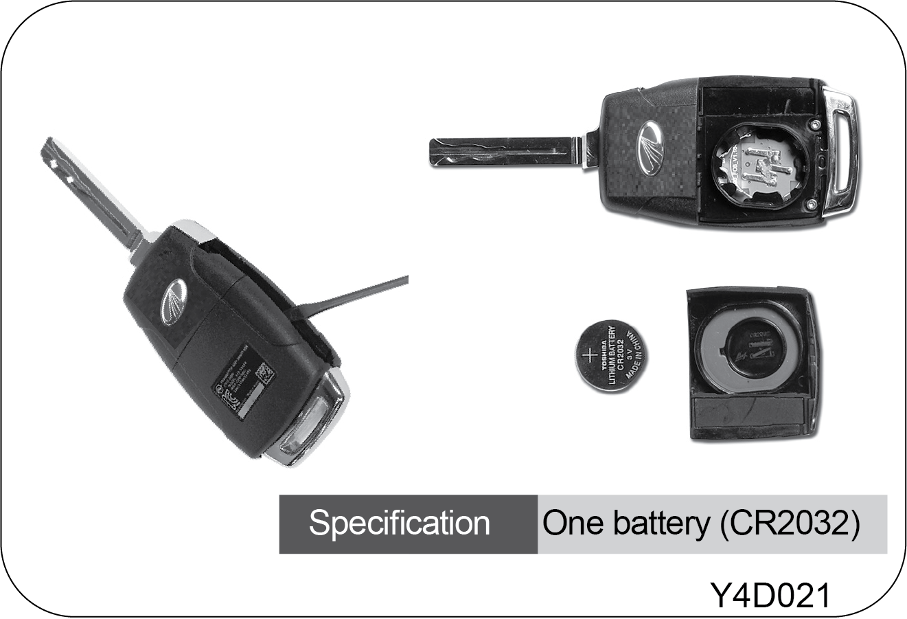
|
Battery Voltage |
3 V |
|
Battery Capacity |
225 mAh |
| • | Remove the cover at the back side of the smart key using a smallest flat-bladed screwdriver, taking care not to scratch the cover |
| • | Remove the rear cover and replace the battery |
| • | Instal a battery (one battery - CR2032)that meets the specifications with the correct polarity |
| • | Assemble in the reverse of removal |

4.7 Gear Selector Lever Positions
4.7.1 P: Park Position

Use this position to park your vehicle, start the engine, warm up the engine, or stay in a location for an extended length
of time. To shift into any other position, depress the brake pedal with the ignition switch in the “ON” position.
| • | Never shift into “P” when the vehicle is moving, or the transmission will be damaged. Stop the vehicle completely before shifting into “P” |
| • | To shift from the “P” position to another position, the ignition switch must be turned to the “ON” position and the brake pedal should be depressed. Any forcible attempts to move the selector lever from “P” without these two procedures may damage the selector lever and transmission |
| • | Do not use the “P” position in place of the parking brake. Always make sure the shift lever is in “P” position and apply the parking brake fully |
4.7.2 Emergency Release From P Position

To shift from the “P”, the ignition switch must be turned to ON and the brake pedal must be depressed. If you cannot shift
out of “P” with the ignition switch in ON, and the brake pedal depressed, apply the parking brake
| • | Turn the ignition off and apply the parking brake |
| • | Push down the shift lock release button. Then, shift the lever to the “N” position |
| • | Start the engine, release the parking brake and shift the lever to the “D” position to drive off |
If the selector lever is locked in the “P” position, release it by following the above instructions and have your vehicle
serviced by the nearest Mahindra Dealer or Mahindra Authorised Service Centre.
4.7.3 R: Reverse Position

Use this position to reverse the vehicle. To shift into “R” from “P” or “N”, completely stop the vehicle and depress the brake
pedal. When the selector lever is in “R”, the parking aid system will be activated (If equipped).
| • | Never shift into “R” when the vehicle is moving |
| • | Please note that the vehicle may slowly move rearward when the selector lever is at “R” |
4.7.4 N: Neutral Position

No power is transferred in this position. At this position, the engine does not transfer power to the wheels and the vehicle
will not move on a flat road. However, for safety, apply the brake when the gear is in this position. To shift into “D” or
“R” position from “N” position after stopping the vehicle, you have to depress the brake pedal with the ignition switch “ON”
| • | Warm up the engine for approx. 3 minutes when the ambient temperature is below -15°C. Otherwise, the gear selector lever may not be moved smoothly (N→R). It is designed for protecting the vehicle and is not a fault |
| • | Never shift into “N” from the “D” position or vice versa when the vehicle is moving, or the transmission will be damaged |
| • | If you have to stop on a hill and would like to use this neutral position, depress the brake pedal firmly |
| • | Never attempt to move the gear selector lever to “N” when the vehicle is in motion |
| • | Never leave a child or pet alone in the vehicle when stopping and parking the vehicle with the ignition ON and the shift lever in neutral “N” position. Move the shift lever to the park “P” position or turn the ignition off in order to prevent the safety accident due to an unintentional operation |
4.7.5 D: Drive Position

Use this position for normal driving conditions. The transmission is automatically shifted from 1st gear up to 7th gears according
to the level of depression on the accelerator pedal and the vehicle speed.
| • | Do not abruptly drive off or sharply accelerate the vehicle after shifting into “D”, or the transmission will be damaged. Especially, when you start off on a hill after stopping and parking the vehicle, wait for a while until the “D” shift indicator comes on with the brake pedal depressed |
| • | Even while the gear is in “D”, the vehicle can roll down on an uphill according to the gradients, so you have to depress the brake pedal |
| • | Please note that the vehicle may slowly move forward on level ground when the selector lever is in “D” |
| • | Shifting to “D” position must be carried out with the vehicle completely stopped. Otherwise, the transmission can be damaged |
| • | Shifting from “N” to “D” position when the ignition is turned ON without the brake pedal depressed is possible. But move the gear shift lever with the brake pedal depressed as much as possible for your own safety |
4.7.6 M: Manual Shift

If the gear selector lever is in this position, you can shift gear manually using the tip switch on the lever and the tip
switches on both sides of the steering wheel.
Upshifting should be done properly according to the road conditions, taking care to keep the engine speed below the red zone.
Manual Gear Selection
Driving gear can be adjusted by operating the tip switch after moving the gear selector lever from “D” to “M” position.

| • | To prevent shift shock and to protect the system, in some cases, the current gear may not be shifted to the lower gear even if the gear selector lever is moved to “M” position |
| • | If you move the gear selector lever into “M” position (manual mode) while the vehicle is stopping, you can shift to the lower gear and the 2nd gear start is possible on snowy or rainy road |
Tip Switch on Gear Selector Lever

|
1 |
Shift up |
2 |
Shift down |
Use of Engine Brake
To use the engine brake, shift the selector lever to the “M” position first, then operate the tip switch to next lower shiftable
gear.
| • | Operate the tip switch only once at a time. If you press and hold the switch, the gear may be shifted through several steps in series |
| • | Abruptly using the engine brake may make driving unstable. Do not use the engine brake abruptly especially when driving on roads covered with snow or ice |
| • | According to the driving conditions, the unexpected gear could be selected during engine braking. In this case, you may feel the shifting shock. Therefore, carefully use the engine brake effect |
4.7.7 Gear Position Display on Instrument Cluster
|
|
1st gear position Use on a rugged road, mountain path and steep hill. Engine braking effect on steep hill is available. |
|
|
2nd gear position Use on a long and gentle slope. Engine braking effect is available. |
|
|
3rd gear position Use on a long and gentle slope. Engine braking effect is available. |
|
|
4th gear position Use on a long and gentle slope. |
|
|
5th gear position |
|
|
6th gear position |
|
|
7th gear position |
Manual Gear Shift Position
|
|
|
| • | Do not downshift abruptly when the vehicle is driven at high speed (D), or vehicle may be severely damaged. Also, the vehicle may slip, resulting in an accident (especially on a slippery road) |
| • | If low-range maximum speeds are exceeded when the selector lever is in low gears, the transmission could be damaged |
| • | If you press and hold the tip switch, the gear may be shifted through several steps in series |
| • | Please note that the gear may be upshifted if you fully depress the accelerator pedal while driving with 1st, 2nd, 3rd, and 4th gear |
| • | If you apply excessive force to the tip switch, the gear may not be shifted into other gears to protect the vehicle system. Soft and smooth operation is recommended |
4.8 Driving Tips For Automatic Transmission
Starting and Driving Off
| • | Always start the engine while the selector lever is in “P” and the brake pedal is depressed. For your safety, avoid starting the engine from “N” even though you can do so |
| • | Check whether or not the engine speed is in a normal operating range (below 1000 rpm). Keep the brake pedal depressed and shift into “D” or “R” |
| • | Depress the brake pedal, release the parking brake, and move the gear selector lever to “D” position. Wait for a while several seconds before driving off with the brake pedal depressed |
| • | To move the vehicle, release the brake pedal and depress the accelerator pedal gradually |
| • | For safe driving, there are P Lock (P => R) and R Lock (N => R) functions, in which the gear shift lever only works with the brake pedal depressed |
| • | When you shift the gear suddenly from D to P, there might be intermittent trapping in N gear, which is normal to protect the transmission, therefore avoid an abrupt gear shift for your safety |
| • | For your safety, always depress the brake pedal before moving the gear selector lever with the vehicle stopped |
| • | Never depress the accelerator pedal when moving the gear selector lever |
| • | If you have to stop on a hill, depress the brake pedal securely |
| • | When starting the engine with the accelerator pedal depressed, your vehicle may abruptly move and cause an accident |
| • | When the parking brake is released while the engine is running at a high rpm, your vehicle may abruptly move. Therefore, wait until the engine speed becomes stable |
| • | To avoid any mechanical damages or accidents, never shift into “P” or “N” while the vehicle is in motion |
| • | When driving at a high speed, any sudden attempt to shift from a higher to a lower gear can severely damage the vehicle. In addition, your vehicle may lose its stability and be at a high risk |
| • | A high engine speed can cause your vehicle to move abruptly from the parked position. To avoid this, wait until the engine rpm becomes stable |
| • | Do not abruptly drive off or sharply accelerate the vehicle after shifting into “D”. Otherwise, the transmission will be damaged. Especially, when you start off on a hill after stopping and parking the vehicle, wait for a while until the “D” shift indicator comes on with the brake pedal depressed |
| • | Do not abruptly drive off or sharply accelerate the engine after shifting into “D”. Otherwise, the transmission will be damaged. Especially, when you start off after stopping, wait for a while until the “D” shift indicator comes on with the brake pedal depressed |
| • | When driving on a downhill, never shift the selector lever to “N”. If you try to shift the lever to “D” from “N”, a sudden gear engagement can damage the drive train |
| • | Even though you can start the engine with the selector lever in both “P” or “N”, for your safety, always start the engine with the selector lever in “P” |
| • | Never shift into “R” when the vehicle is moving |
Creep Phenomenon
Without any depression of the accelerator pedal, your vehicle can move slowly if the selector lever is in any position other
than “P” or “N”. This is called the creep effect. You can control your vehicle’s movement by only applying the brake in heavy
traffic or narrow areas.
| • | On a steep decline or incline, your vehicle may move in the opposite direction of the intended direction in spite of the creep effect. When stopping on a steep hill, always depress the brake pedal |
Kickdown Function
If you need to accelerate rapidly, depress the accelerator pedal to its travel end. Then, a lower gear will be automatically
engaged. This is called the Kickdown function.
| • | Do not use the kickdown function while driving on slippery or sharply curved roads |
| • | If you use the kickdown function too frequently, the durability and fuel economy of the vehicle will get worse |
Engine Brake
When the accelerator pedal is released while the vehicle is in motion, the engine speed decreases. This decreased engine speed
creates an extra braking force. On a downhill, engaging a lower gear can generate a slower engine speed and eventually slow
down the vehicle speed. By using this engine brake, you can decrease your vehicle speed without excessively using the brake
system. The lower gear, the higher braking force.
| • | Do not excessively apply the brake pedal while going down a long slope. The brake system will overheat, experience vapour lock or the fade phenomenon, and lose the braking force |
| • | Be aware that the engine brake does not work when the gear selector lever is in the “N” position |
| • | Avoid any abrupt engine braking on slippery roads, or the tyres may slip |
4.9 Safety Mode (Automatic Transmission)
4.9.1 Symptoms
When the transmission has an electrical or mechanical fault, the transmission operates in the safety mode to maintain minimum
driving conditions and to prevent the transmission from being damaged. When the transmission is defective, the symptoms that
can occur are as follows:
| • | Heavy shock when moving the selector lever |
| • | Decreased driving force while driving at high speed |
| • | Fixed gear position during driving (cannot accelerate the vehicle) |
| • | If you find any symptoms caused by mechanical or electrical defects in the transmission, stop the vehicle immediately and reset the safety mode |
| • | If abnormal operation of the transmission (fixed at the certain forward gear in “D” or 2nd reverse gear in “R”) still exists, have the system checked by a Mahindra Dealer or Mahindra Authorised Service Centre |
| • | If the mechanical or electrical problem still exists, have the system checked by a Mahindra Dealer or Mahindra Authorised Service Centre |
4.9.2 Resetting The Safety Mode When The Gear Is Fixed
How to reset the safety mode
| • | Park the vehicle and place the selector lever to “P” |
| • | Stop the engine and wait for more than 10 seconds |
| • | Start the engine |
Symptoms after resetting the safety mode
| • | If the vehicle operates normally after resetting, the problems are corrected |
| • | If gear is fixed at the 2nd forward gear in the “D” position or the 2nd reverse gear in “R”, have the system checked by a Mahindra Dealer or Mahindra Authorised Service Centre |
4.10 Road Safety
4.10.1 Driving On A Snowy Or Icy Road
| • | Shift to the lowest possible gear and drive slowly |
| • | Since your braking distance is longer than usual, allow a longer following distance |
| • | If you accelerate or brake too fast, your vehicle will slide and you might get in an accident, so drive with caution. When braking, use the engine brake; apply your brakes only after you have slowed down considerably |
| • | When going down a slippery downhill, use the engine brake and drive slowly |
When travellingon a snowy or icy road, use snow tyres for safer driving.
4.10.2 Driving On A Sandy Or Muddy Road
| • | Keep your speed steady as low as possible |
| • | While driving, be careful not to accelerate or stop too quickly because you might get stuck in sand or mud |
| • | If your vehicle gets stuck in sand or mud, insert a rock or a piece of wood under the stuck wheel, lightly apply the accelerator pedal and gently shift back and forth between the reverse and forward gear to allow inertia to get your vehicle out |
When your vehicle is stuck in sand or mud and you step on the accelerator pedal excessively in order to get out of there,
the tyre slip may occur which results in the damage of the transmission and corresponding drive system. In that case, get
another vehicle to tow you if possible.
4.10.3 Driving On Unpaved And Mountain Roads
| • | Before driving, check road conditions such as if the road suddenly ends, or if there is enough space for a U-turn in the middle of the road |
| • | It’s easy to slide in a road covered with much sand or with much dry dirt. Keep your speed low and steady |
| • | There is a danger of driving off the mountain road, so stay alert |
| • | When coasting downhill, do not change gears; go down slowly by applying the engine brake |
In high mountain area the operation stability of diesel engine is not guaranteed in high mountainous area over 2,500 metres..
The short trip such as passing through tunnel in this area is acceptable. However, do not keep driving there for a long time.
If you drive your vehicle in very high altitude for long time, the engine could be damaged. The engine power, climbing ability
and emission are subject to the altitude.
4.10.4 Going Through Water
| • | If water gets into the electric system or engine, it might cause irreparable damage to your vehicle. Please refrain from underwater driving |
| • | If going through water is unavoidable, choose a shallow spot where the exhaust outlet wouldn’t get submerged in water and proceed slowly at a steady speed |
| • | Before going through water, get out of your vehicle and check the bottom of the river. Do not go through water if the bottom is sandy or covered with big rocks |
| • | If several vehicles are going through water together, the first vehicle might burrow into the bottom, so be careful and cross in a different place if possible |
Important things to remember when going through water
| • | If the engine stops while you are going through water, do not try to restart. Get your vehicle towed |
| • | Be particularly careful not to allow water to enter into the engine through the air cleaner |
| • | Never change gears while going through water |
If water gets into the brake system, the effectiveness of the brakes decreases. After going through water, move slowly and
gently applying the brakes several times so that frictional heat dries the brake pads and discs. Check if the brakes work
properly before continuing driving
Checking your vehicle after going through water
| • | Check the front, rear, right and left sides, transmission, axle hubs, propeller shaft, oil and fluid levels, and underbody; if you discover problems, get your vehicle checked immediately |
| • | Check all lamps and other electrical devices. If necessary, replace damaged components and get your vehicle checked |
| • | Check for damages to the vehicle body and underbody; if you discover problems, get your vehicle checked immediately |
| • | If the vehicle body is very dirty, wash your car to protect it |
4.10.5 Driving On Hill Roads
Position the gearshift lever in accordance with the road conditions
| • | If you suddenly use the engine brake on an icy or slippery road, the vehicle might slide and get in an accident. Use the engine brakes after fully reducing your vehicle speed |
| • | If you repeatedly apply your brakes on a long downgrade, they may overheat, their effectiveness decreases and an accident might occur. When on a long downgrade, use the engine brake together with your brakes |
If you suddenly apply the engine brake while travellingat a high speed, the engine may get damaged. Slow down the vehicle
speed and then downshift the gear.
4.10.6 High way/Express way Driving
| • | Before getting on a High way/Express way, listen to the weather forecast, prepare thoroughly and check the fuel level, brake system, cooling system, and tyres |
| • | Always respect the speed limit and refrain from speeding |
| • | Allow for a safe following distance, avoid sudden steering movements |
| • | When it rains or snows and the weather conditions are adverse, double the distance between your vehicle and the vehicle running in front of you. And reduce your speed by half |
| • | Do not idle the engine for a long time; it wastes fuel and causes environmental pollution |
| • | Drive at a slow speed for the first 2 km if possible |
| • | Do not load your vehicle with unnecessary stuff |
| • | Refrain from quick accelerating and abrupt braking, travel at a steady speed |
| • | When you park or stop for a long time, turn the engine off |
| • | Keep tyres at the recommended pressure |
| • | Keep your vehicle in the best possible condition by periodically checking it and perform maintenance |
4.11 Caring For Your Vehicle in Winter
During the winter, undesirable road conditions frequently happen. Therefore, appropriate preparations for emergencies should
occur. Before driving in suburban or rural areas, or on a snowing day, have bags of sand, snow chains, a shovel, gloves, and
old clothes in your vehicle
Coolant
Before it gets cold, check the coolant level. If only water has been added into the coolant reservoir, the engine and the
cooling system of your vehicle may seriously be damaged when the water freezes as it gets below the freezing point. Use recommended
coolant.
| • | When the vehicle is shipped, the cooling system is filled with a four-season coolant |
| • | Before adding or refilling coolant, ensure that the coolant is a 50:50 mixture of water and antifreeze |
| • | Use only Mahindra genuine coolant |
Washer Fluid
Use a genuine washer fluid that does not freeze on a cold day. When non-recommended washer liquid is used, the liquid may
form an ice. This will damage the wiper motor and hinder your safe driving.
Engine Oil
When the vehicle is shipped, the engine is filled with Maximile engine oil.
Tyres
Snow tyres are more desirable on an icy or snow-covered road. Have snow tyres installed on your vehicle before driving on
such a road.
| • | When snow tyres are installed, drive your vehicle at a lower speed than normal |
| • | Instal snow chains correctly. Otherwise, the chains may damage the wheelhouses or the body of your vehicle |
Air Conditioner
When the air conditioner has not been used for an extended period of time, internal moving components may become seized because
the lubricating system has not worked for a prolonged amount of time. As a result, the refrigerant may leak or rusting may
happen to the system. Malfunction of the air conditioner may result. To maintain its optimal operating condition, it is recommended
that the air conditioner be turned on for approximately 5 to 10 minutes every week throughout all seasons.
Do not remove the refrigerant in winter, even though you do not use the air conditioner.
4.11.1 Starting The Engine And Driving In Winter
During winter, the engine experiences increased resistance from the powertrain. Therefore, start the engine in an appropriate
way. After starting the engine, allow time to warm it up before driving the vehicle. Warming up the engine will increase its
life expectancy and help you drive safely.
| • | The glow plugs of the diesel engine should sufficiently be warmed up before the engine starts |
| • | Change the engine oil and fuel filter according to the specified service intervals. Contaminated engine oil will decrease its viscosity and clog the fuel filter and oil filter, causing a difficulty of engine start at low temperature |
| • | Do not add any additives other than the genuine fuel for better startability at owner’s disposal. The additive may decrease the lubricating ability of the internal fuel system; the additive may have a different flashing point. This will damage the fuel system or produce an excessive exhaust fume |
Driving in Winter
Maintain at least twice as long of a normal driving distance between your vehicle and the vehicle in front of you. When stopping,
shift into a lower gear to use the engine brake. Avoid speeding, abrupt acceleration, sudden braking, or drastic manoeuvring
of the steering wheel.
4.11.2 Parking In Winter
When the parking brake is applied in cold weather, ice may form on the brake system and cause some difficulty moving the vehicle.
When parking on a hill, first, apply the parking brake. Put the shift lever into the “P” position. Put a chock under a tyre
and release the parking brake.
When ice forms on the parking brake system, an attempt to move the vehicle without removing the ice may damage your vehicle.
Wait until the ice melts away and gently move your vehicle.
4.11.3 Other Maintenance
After driving on a calcium chloride (salt) sprayed road, wash the bottom of your vehicle as soon as possible to avoid any
rust. When parking on a snow-covered road, the brake system may begin to have some ice on it. The ice will decrease your vehicle’s
braking ability. If this happens, drive at a low speed and use the brake frequently to remove the ice. After regaining the
braking ability, drive your vehicle at a normal speed.
| • | When there is ice on the wiper blades, turning on the wiper switch may put an extra burden on the wiper motor and damage it. Avoid using the wipers when ice is on the blades |
| • | When driving on a snow-covered road, a large amount of snow may build up under each wheelhouse. This buildup prevents the steering wheel from moving freely. Therefore, remove the snow buildup frequently |
4.11.4 Diesel Fuel in Winter
On an extremely cold day, paraffin, one of the chemicals in diesel fuel, may separate from the diesel fuel. This separation
makes starting the engine difficult. Therefore, to ensure an easy start on a cold day, park your vehicle inside of a garage.
If possible, fill up the fuel tank after each driving to prevent ice from forming inside of the fuel system.
| • | Change engine oil and the fuel filter as scheduled. Contaminated engine oil will lose its viscosity, clog the fuel filter and oil filter and cause difficulties starting the engine |
| • | Do not add any additives other than the genuine fuel for better startability at owner’s disposal. The additive may decrease the lubricating ability of the internal fuel system; the additive may have a different flashing point. This will damage the fuel system or produce an excessive exhaust fume |
4.12 Turbocharger System
Insufficient oil supply to the bearing assembly in turbocharger may cause the turbocharger to seize. Therefore, the following
cares are necessary to prevent the seizure:
| • | Use only the specified engine oil and observe inspection and replacement intervals |
| • | Operate the engine over the idling speed only after normal engine oil pressure has been established. Forcing the turbocharger to operate before the bearings are adequately lubricated creates unnecessary friction |
| • | After starting the engine, let it run for approx. 2 minutes at idle speed (Avoid acceleration or driving off the vehicle) |
| • | Do not stop the engine immediately after coming back from high load driving (such as high speed driving or driving on long slope). Let the engine run for approx. 1 minute at idle speed to cool it down |
| • | After changing the engine oil and oil filter, start the engine and let it run for approx. 1 minute at idle speed (Avoid acceleration or driving off the vehicle) |
| • | Do not rev the engine at high speed without air cleaner element when checking the engine |
Turbocharger
The turbocharger consists of two turbo elements, a turbine and a compressor, both of which are driven from the main Centre
shaft. The turbine rotates between 50,000 ~ 1,60,000 revolutions per minute and uses the energy of the exhaust gas to drive
the compressor. The compressor, in turn, draws in fresh air which it supplies to the cylinders in the form of compressed air.
4.13 Using low quality fuel
The fuel system of the common rail direct injection engine is precisely machined component. Using low quality fuel could result
in a serious damage to the engine due to the water, impurities or suspended particles in fuel. Power loss, engine idling problem,
engine stall, difficulty with starting the engine in cold weather as well as damage to the engine and the fuel system, due
to the naturally produced suspended particles. If any product in which the biodiesel fuel exceeds the total amount of fuel
is used or the aftermarket biodiesel fuel is added to the regular fuel, it can lead to malfunctions in the vehicle and this
is not covered by warranty.
4.14 Four-Wheel Drive System (if equipped)
4.14.1 4-Wheel Drive Switch

When switching to 4WD mode select a proper driving mode according to the road conditions (slippery, gradient, bump or dip).
Switching between 2H and 4H
It is recommended to shift under a speed of 70 km while the vehicle is being driven.
Switching between 2H and 4H/4L
Stop the vehicle on a level ground and place the shift lever into the “Neutral” position. Turn the switch to the desired position.
Do not drive off before the 4WD indicator (4H/4L) is illuminated. Driving off before illumination of this indicator can cause
abnormal wear or stuck of drive gears.
4.14.2 4WD Indicator
4WD HIGH Indicator
When shifting the driving mode from “2H” to “4H”, this indicator comes on
When shifting the driving mode from “4L” to “4H”, this indicator blinks until the shifting operation is completed. After completion
of the mode change to 4H, the indicator comes on.
4WD LOW Indicator
When shifting the driving mode to “4L”, this indicator blinks until the shifting operation is completed. After completion
of the mode change to 4L, the indicator comes on.
4WD CHECK Warning Indicator
If this warning light comes on while driving, have the 4WD system checked by Mahindra Dealer or Mahindra Authorised Service
Centre.
4.14.3 Driving Mode

2H : 2-Wheel Drive
This is rear wheel drive with high speed. Use this position for normal driving. This position gives greater fuel economy,
quieter ride and least drive train wear.

4H : 4-Wheel Drive, High
Use this position on wet or slippery roads such as sandy, muddy or snow-covered roads.

4L : 4-Wheel Drive, Low
Use this position for maximum traction.
4-Wheel Drive System
Transfer case which allows you, in the case of part-time 4-wheel drive, to switch between 2-wheel drive and 4-wheel drive.
Compared with 2-wheel drive vehicles, this system provides more stable driving conditions. This system ensures a more stable
drive on wet or slippery roads. In case the greater traction is needed, you can shift into 4 Wheel Drive Low (4L).
Part-Time 4-Wheel Drive
Normally, the vehicle is driven in 2WD mode. But if needed, it can be changed into 4WD High (4H), and 4WD Low (4L) by pressing
the switch. This is equipped with the control unit that supports the mode transfer. In 4WD mode, the system splits the torque
between the front (50%) and rear (50%) wheels.
Tight Cornering
Cornering a curve in 4WD mode (4L or 4H) may shake up the vehicle or cause skidding. Such phenomena indicate that the 4–wheel
drive is operated normally, because they can be caused by the resistance of the internal power system according to the difference
of rotation between the front and rear wheels. Please avoid excessive and tight cornering in 4-wheel drive mode to prevent
the power-train from being damaged.
Cautions when using 4-wheel drive mode
| • | There could be mechanical noises and shocks during mode changes. However, these are normal conditions due to the mode changing operations |
| • | Use only the 2H mode on a normal paved surface. Do not drive your vehicle in the “4H” or “4L” position on paved road surfaces. Doing so will result in damages to the drive train |
| • | Driving in a 4-wheel mode on a normal paved surface will cause unwanted noises, premature wear of tyres, or increased fuel consumption |
| • | To shift from “4L” into another mode or vice versa, stop the vehicle and depress the brake pedal before any shift |
| • | If the “4WD CHECK” warning light stays on, have the 4WD system checked by the nearest Mahindra Dealer or Mahindra Authorised Service Centre |
| • | When cornering a curved road in a 4-wheel drive mode (4L or 4H), there could be some mechanical shocks and resistances in vehicle’s drive train. These are normal conditions due to internal resistance in the drive train when the 4-wheel drive mode is properly working. To avoid damages to the drive train, do not drive your vehicle at an excessively high speed on a sharply curved road |
| • | This helps to make the mode changes easily |
| • | Drive the vehicle at the speed of 80 km/h or less when driving in 4H mode |
| • | We hope you will use 4L mode when high traction is required |
| • | Be sure to use the same size and type tyres of the same manufacturer on all wheels so that the vehicle characteristics can be maintained safely |
| • | The vehicle equipped with 4WD system should be towed by flat-bed truck. If it is impossible to load the vehicle on a flat-bed truck, tow the vehicle after placing dollyies under all tyres. If you tow the vehicle equipped with 4WD system while front or rear tyres are rolling on the road, the drive system in the vehicle should be severely damaged |

4.15 Brake System
|
Warning Light and Indicator Related to Brake
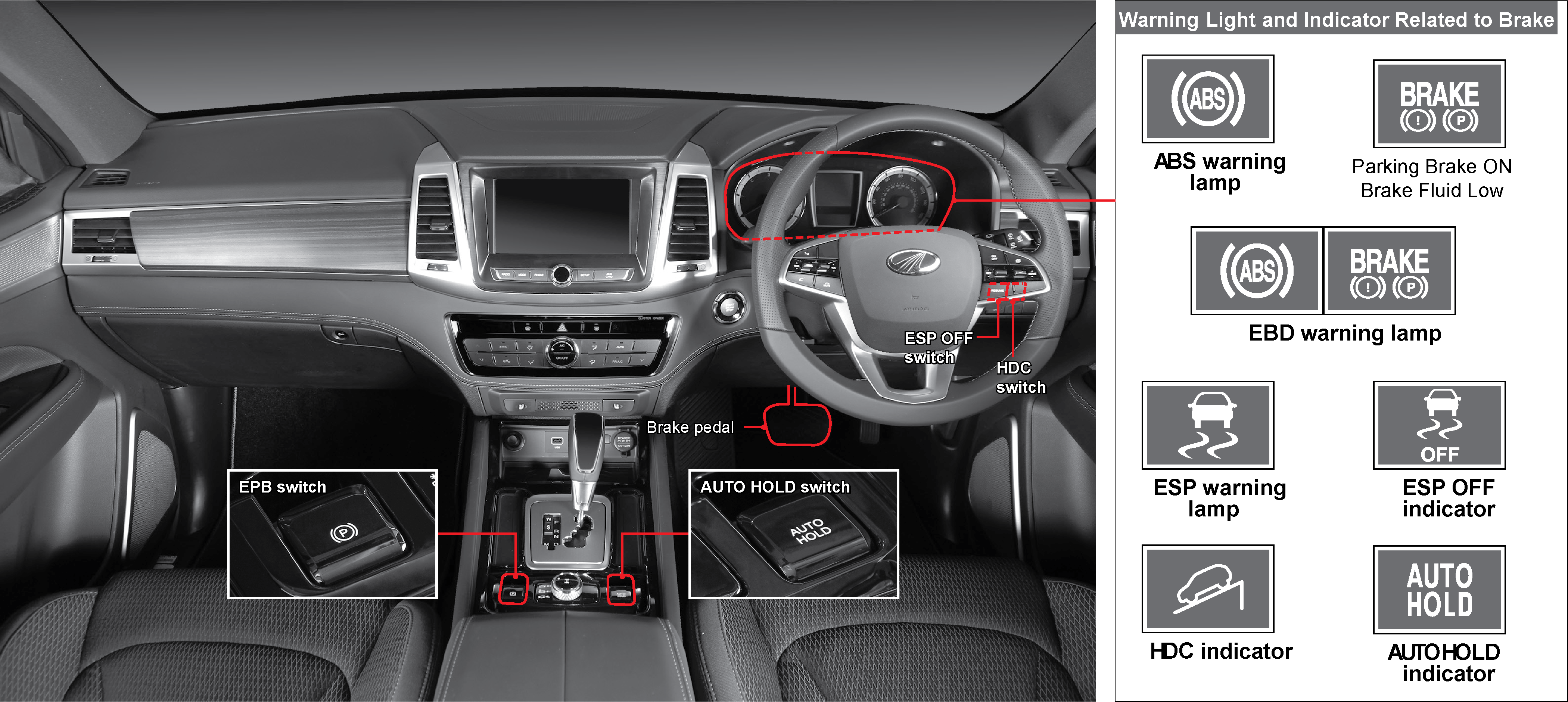 |
4.15.1 Brake Pedal (Foot Brake)
The brake pedal (foot brake) is designed to decrease the vehicle speed and stop the vehicle. Do not excessively apply the
brake pedal while going down a long hill. The brake system will overheat causing the vapour lock or fade phenomenon thus losing
braking force. Use the foot brake along with the engine braking effects by selecting lower gears.
Avoid abrupt engine braking on slippery roads, or the tyres may slip.
Engine brake
A system that allows for the slowing of a vehicle that is independent of the conventional braking systems. A driver would
normally down-shift to slow the driver’s descent of a hill, using engine compression. The engine brake increases the effectiveness
of this regarding force.
Fade
Reduction or loss in braking force due to loss of friction between brake pads and discs.
Vapour Lock
When the brake system is overheated, the fluid in the brake lines will boil and form bubbles. Only the bubbles will be compressed
when the brake pedal is depressed. So the brakes cannot work properly due to loss of braking force.
Nothing under driver’s seat

Do not leave empty bottles or cans near or under the driver’s seat. If it hinders the brake or accelerator pedal operation,
it may cause an unexpected accident.
Brake pad
Check the brake pad at every 10,000 km of driving, and replace if necessary. When the brake pad are badly worn, you may hear
a squeaking sound from the brake system. If this happens, replace the brake discs as a set (left and right) as soon as possible.
The lifespan of brake pad depends on the driving habits.
4.15.2 ABS (Anti-Lock Brake System)
ABS (Anti-Lock Brake System)
When braking suddenly or braking on slippery roads, the vehicle keeps moving forward but the wheels are locking and not rotating.
If these happen, your vehicle may lose stability or rotate resulting in an accident. ABS helps to maintain directional stability
and control of the vehicle.
ABS Warning Light
This warning light comes on when the ignition switch is turned to “ON” and should go off in a few seconds.
If this light stays on after starting the engine or comes on while driving, have the system checked by Mahindra Dealer or
Mahindra Authorised Service Centre. In this case, the ABS function is not available, but the conventional brake system is
properly working.
| • | ABS is designed to secure more safety and increase the control of steering wheel during emergency braking situation. The braking distance for vehicles equipped with an ABS may be longer than for those without it on uneven, gravel, rough or snow-covered roads |
| • | While driving on these roads, reduce the vehicle speed and maintain a safe distance from a proceeding car |
| • | To get the maximum benefit from ABS in an emergency situation, do not pump the brake pedal |
| • | Even a vehicle equipped with ABS has a risk of skidding sideways. Therefore, always maintain a safe distance from the vehicle ahead and drive at low speed on slippery surfaces |
| • | ABS system performs self diagnosis by transferring hydraulic pressure to the brake units for few seconds after starting the engine. This may cause some noise and vibrations. This means ABS is properly functioning |
| • | When the ABS is operating, you may feel pulsations from the brake pedal along with noise. This is normal and indicates that the ABS is functioning properly |
4.15.3 EBD (Electronic Brake-Force Distribution)
(if equipped)
(if equipped)
EBD (Electronic Brake-force Distribution)?
When the brake pedal is applied, it controls the braking pressure electronically to effectively distribute the braking forces
to the front wheels and rear wheels. EBD operates when the speed differences between the fastest front wheel and the rear
wheel are over
1 km/h. If ABS is engaged, it does not operate.
1 km/h. If ABS is engaged, it does not operate.
EBD Warning Light (if equipped)
If the ABS warning light and the brake warning light come on simultaneously, EBD (Electronic Brake-force Distribution) system
is defective.
If the EBD warning light stays on, have the system checked at the Mahindra Dealer or Mahindra Authorised Service Centre.
4.15.4 ESS (Emergency Stop Signal)
Emergency Stop Signal
The hazard warning flashers very rapidly blink to inform the emergency situation to the vehicles behind when your vehicle
brakes are applied suddenly or ABS is operating
The hazard warning flashers will go off:
| • | When you press the hazard warning flasher switch |
| • | After 10 seconds |
| • | When the vehicle speed increases by 10 km/h |
| • | The ESS does not work when the hazard warning flashers are already ON |
| • | Operation of ESS is subject to the vehicle speed and driving conditions |
4.15.5 ESP (Electronic Stability Program) (if equipped)
ESP System
The ESP system is an electronic vehicle stability control and safe driving system and driving safety supplementary system
that helps to avoid dangerous situations by controlling the brakes on the wheels or the engine torque to compensate vehicle
stability when it is extremely unstable under conditions such as sharp cornering.

ESP OFF switch
When the switch is pressed and held for 3 seconds or longer, the ESP is deactivated and the ESP OFF indicator is illuminated
on the instrument cluster. Pressing the switch again resumes the ESP function.
ESP Indicator/Warning Light
ON
This warning light comes on when ESP system is defective.
Blinking
This indicator blinks when the ESP system is operating.
For your safety, reduce the vehicle speed when the indicator is blinking or you are driving on a slippery or curved road.
ESP OFF Indicator
This indicator comes on when pressing the ESP OFF switch to deactivate the ESP function. When the wheels are slipping on a
snow-covered or iced road, you can stop ESP function by pressing ESP OFF switch. This may help to drive off the vehicle.
| • | The vehicles equipped with ESP perform self-diagnosis on the system when the vehicle starts to move after engine start. During that time, a slight vibration can be felt which means ESP is properly functioning |
| • | When the ESP system is operating, you may feel the slight pulsation. This is normal and indicates that the ESP is functioning properly |
For details, refer to ESP OFF switch and ESP system in Chapter 3.
Stopping ESP Function With ESP OFF Switch
If the driving wheels are slipping on snowy or icy roads, the engine rpm may not increase even when you depress the accelerator
pedal, and accordingly, you may not be able to move your vehicle. In this case, stop the ESP function by pressing the ESP
OFF switch. When the ESP OFF switch is pressed, the ESP function stops and the vehicle is driven independently from the sensor
outputs.
Sensing ESP System In Operation
When ESP is activated (ESP indicator light blinks) due to sharp cornering and etc., you will sense that the corresponding
tyre is put on the brake, and brake pedal vibration and other noises can occur due to hydraulic pressure change in the system.
Also the engine torque may not increase even with the accelerator pedal depressed, due to engine power control function.
Vehicles equipped with ESP system have more auxiliary functions to reinforce the driving safety, other than major functions
below.
BAS (Brake Assist System) Function
A certain driver such as a female driver, aged driver, or a driver with a disability is unable to depress the brake pedal
as hard as necessary. When the ESP system recognises any emergency situations requiring hard braking, it automatically delivers
an extra high braking pressure to the wheels.
ARP: (Active Rollover Protection) Function
This function is a part of the ESP system. When your vehicle moves in an extremely unstable manner, this function helps the
vehicle to maintain normal stability.
| • | The ARP system more powerfully controls the engine and each wheel than the ESP function. When the ARP is applied, a sudden decrease of vehicle speed or powerful braking force can make steering your vehicle a little difficult |
| • | The ESP system does not operate during reverse driving |
| • | The ESP system is activated when the vehicle is unstable to correct the vehicle stability. When the ESP indicator is blinking, reduce the speed and pay extra attention to the road |
| • | The ESP system is only a supplementary device for the vehicle. When the vehicle exceeds its physical limits, it cannot be controlled. Do not rely on the system. Keep driving safely |
| • | It is normal for the vehicles with ESP to emit a slight vibration during performing self-diagnosis procedures |
| • | When ESP is applied, you may feel some noise or vibration from the brake pedal or other relevant systems. They are caused by pressure changes in the relevant systems |
| • | Do not drive off the vehicle immediately after starting the engine. The ESP system needs approx. 2 seconds to perform self diagnosis. If the system could not complete the self-diagnosis, the ESP system cannot be activated even when the vehicle is in unstable conditions |
| • | Do not accelerate the vehicle and drive slowly when the ESP indicator flashes |
| • | Do not press the ESP OFF switch when the ESP system is in operation. Stopping the ESP function on the slippery road may cause a serious accident. To deactivate the ESP function, press the ESP OFF switch only on a long straight road |
If the ESP OFF indicator comes on with the ESP system still activated, the ESP related system is defective. Make sure to have
the vehicle checked at the nearest Mahindra Dealer or Mahindra Authorised Service Centre
4.15.6 HDC (Hill Descent Control) (if equipped)
HDC (Hill Descent Control)
When travelling down steep grades, this function allows you to travel at a low speed without depressing the brake pedal. This
convenient function is only for driving down steep grades. Therefore, do not use this function for anything other than driving
down steep hills.

HDC Switch
Pressing the HDC switch turns on the HDC indicator on the instrument cluster and set the HDC system in READY mode. Pressing
the HDC switch again turns off the HDC indicator and deactivates the HDC function.
HDC Indicator
Green light on
HDC is ready for use (by pressing the HDC switch).
Green light blinking
HDC is being applied.
Red light on
The HDC system is overheated or malfunctioning.
If driving on a level road with HDC on and ready for use, HDC may be applied during sharp cornering or passing over a speed
bump. Therefore, do not activate HDC while driving on normal roads.
HDC Operating Conditions
| • | HDC switch ON (green HDC indicator on instrument cluster comes on) |
| • | Gradient of more than specified value and vehicle speed between 5 and 50 km/h |
| • | ESP (including BAS) not activated |
HDC Deactivation Conditions
| • | HDC switch OFF (green HDC indicator on the instrument cluster goes off) |
| • | Gradient of less than specified value |
| • | Vehicle speed of below 5 km/h or above 70 km/h |
| • | HDC malfunction |
| • | HDC system overheated |
While the HDC is activated, you can drive the vehicle at a speed between 5 and 30 km/h by depressing the brake pedal (deceleration)
or accelerator pedal (acceleration). If the vehicle speed is below 5 km/h or above 70 km/h, the HDC is deactivated.
HDC Operation
If the conditions for activating the HDC are met, HDC is activated and the green HDC indicator blinks on the instrument cluster.
The HDC is deactivated when the vehicle speed is below 5 km/h or above 70 km/h or the gradient of the slope becomes gentle
while it is in operation. It is normal that strong vibrations and noise occur from the brake system when the HDC is in operation.
| • | HDC is designed to be used when driving on off-road with steep grades (downhill) |
| • | Unnecessary usage of HDC can cause malfunctions in the brake system or ESP system. Do not use HDC when driving on normal roads |
| • | If driving on a level road with HDC ON and in ready state, the HDC function can be operated during sharp cornering or passing over a speed bump. Therefore, do not activate the HDC while driving on normal roads. |
| • | If the red HDC indicator is turned on, the HDC system is overheated or faulty. If the red indicator stays on even after the HDC related systems have been cooled down, have the vehicle checked and serviced at the nearest Mahindra Dealer or Mahindra Authorised Service Centre |
| • | It is normal for the HDC related system including the brake pedal to emit operating sounds and vibration when HDC is operated |
4.16 EPB (Electric Parking Brake)
The EPB (Electric Parking Brake) is applied/released by simple switch operation. This parking brake system improves vehicle
safety and stability.

4.16.1 Applying EPB
Park the vehicle in a safe place and pull up the EPB switch.
The parking brake warning lamp on the instrument cluster is turned on, indicating that the parking brake is applied.

4.16.2 Releasing EPB
Press down the EPB switch with the brake pedal depressed.
The parking brake warning lamp on the instrument cluster is turned off, indicating that the parking brake is released.

4.16.3 AUTO Releasing EPB
| 1. | Close the driver door, engine hood and tailgate and fasten your seat belt. |
| 2. | Shift the gear selector lever to the R or D position. |
| 3. | Release the brake pedal and then depress the accelerator pedal slowly. |
| 4. | The EPB is released automatically, thus enabling forward or backward movement of the vehicle. |
The EPB AUTO release function will not be activated when the driver door, engine hood or tailgate is not closed or the seat
belt is not fastened.
4.16.4 EPB Warning Lamp / Parking Brake Warning Lamp
|
|
Warning Lamp ON: The warning lamp is turned on when there is a fault in the EPB system. |
|
|
Warning Lamp ON:
When parking brake is applied properly.
When brake fluid level is low.
When gear selector lever is shifted to P position with AUTO HOLD. |
| • | Check if the parking brake warning lamp is turned on or off on the instrument cluster when applying or releasing the EPB |
| • | Improper operation of EPB switch (operating with excessive force applied, continuous operation) may turn on the EPB warning lamp. If this is the case, turn the ignition switch off and then on again. The warning lamp will be turned off, indicating that the EPB works normally |
| • | If the EPB warning lamp stays on, have the vehicle serviced at a Mahindra Dealer or Mahindra Authorised Service Centre. |
| • | If you have to park the vehicle with faulty EPB, safely pull over and stop the vehicle on a flat surface and shift the gear selector lever to the P position. |
Do not let other people who are not familiar with the EPB system or children operate the EPB switch. There is a danger of
accidents depending on the parking/stationary state of the vehicle.
4.16.5 EPB Emergency Mode
If the brake pedal cannot be depressed because of the brake system failure while driving the vehicle, brake the vehicle by
pulling up the EPB switch. The parking brake is applied as long as the switch is pulled up. If this is the case, it may take
longer to stop the vehicle.
| • | Activating this emergency mode may have a negative effect on the vehicle. Therefore, this feature only be used in an emergency |
| • | If you hear noises or smell a burnt odour from the related components after using the EPB emergency mode, have the vehicle checked and serviced at a Mahindra Dealer or Mahindra Authorised Service Centre |
| • | Do not use this feature while driving except for emergency. Using this feature not only damages the vehicle system, but also can cause accidents due to braking force |
| • | Keep the EPB switch out of the reach of children. Failure to do so could cause an accident |
| • | If there is a critical fault in the brake system, the EPB emergency mode may not work |
4.17 Double Parking
4.17.1 Double Parking
To park the vehicle in front of another vehicle allowing the vehicle to be pushed or pulled, perform the following procedure:

| 1. | Release the EPB with the ignition switch ON or engine running. |
| 2. | Turn the ignition off with brake pedal depressed and gear selector lever in the P position.
 |
| 3. | Shift the gear selector lever to the N position after pressing the lever lock release button with the brake pedal depressed.
 |
Make sure that the AUTO HOLD function is deactivated by pressing the AUTO HOLD switch. If AUTO HOLD is activated, the EPB
is automatically applied.
If the gear selector lever is in a position other than the P position, the vehicle power will not be turned off.
In double parking mode, the vehicle may roll away. Therefore, the vehicle should be parked on a flat surface and taking the
appropriate action, such as installing wheel chocks, is required.
| • | Before driving off, be sure to check if the parking brake warning lamp or brake fluid low warning lamp is turned on |
| • | Driving with parking brake applied could damage the brake system. Before driving, fully release the parking brake |
| • | If the parking brake should be applied while driving the vehicle, move the gear selector lever to the P or N position for safety |
| • | If the brake warning lamp stays on after the parking brake is released, have the vehicle checked and serviced at a Mahindra Dealer or Mahindra Authorised Service Centre |
| • | For vehicles with A/T, never use the gear position P (parking) as a substitute for the parking brake. When parking/stopping the vehicle, always apply the parking brake |
| • | To park the vehicle with gear selector lever in the N position, turn the ignition switch off with the gear in the P position and move the gear selector lever to the N position after pressing the lever lock release button |
| • | If the gear selector lever of the parked/stopped vehicle is in a place other than the P position, the vehicle can be rolled away based on the external force applied or slopes of the road. Therefore, always move the gear selector lever to the P position unless other gear position is required |
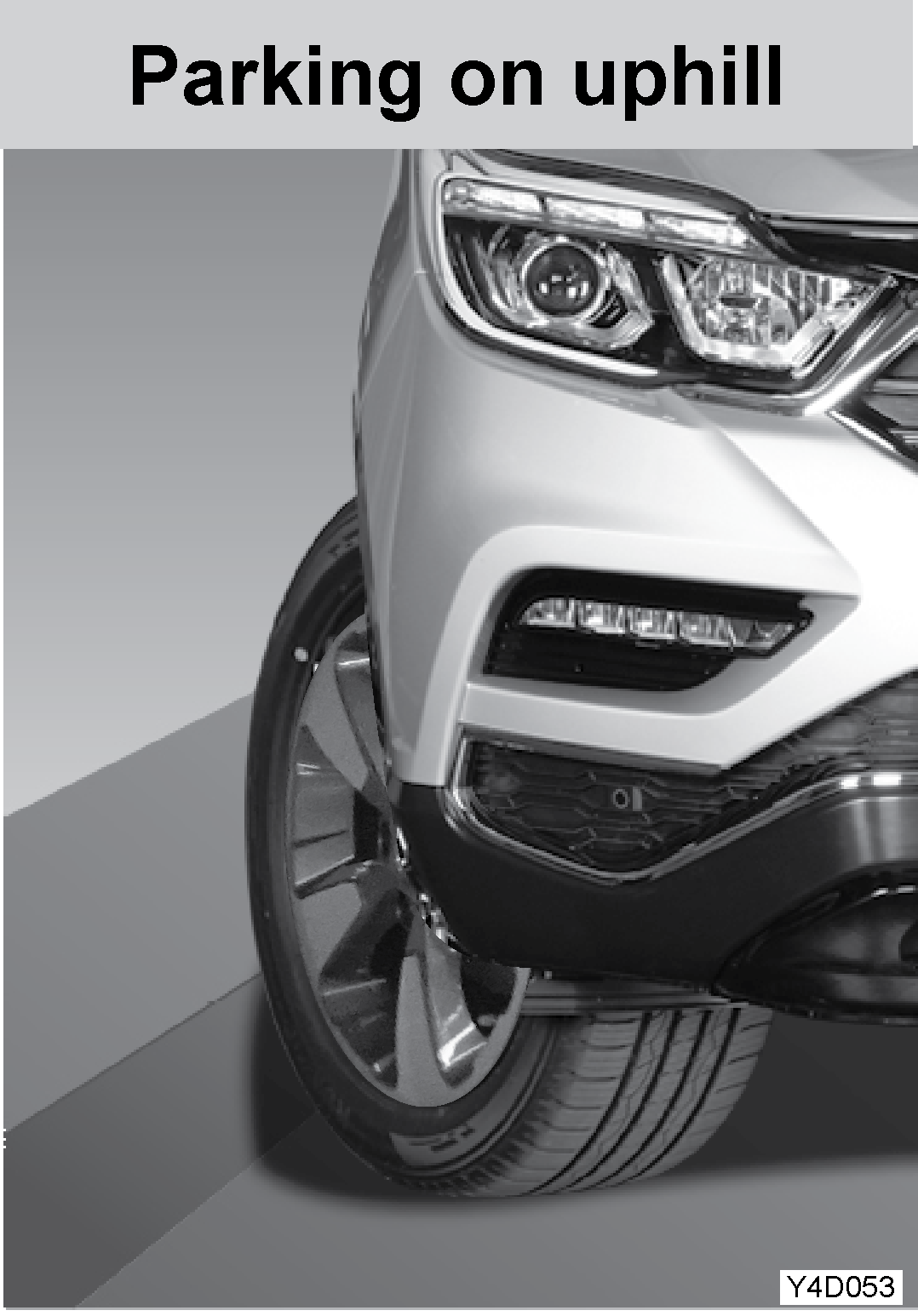 |
When parking on an uphill, turn the front wheels away from the curb
|
 |
When parking on a downhill, turn the front wheels toward the curb
|
4.18 AUTO Hold (if equipped)
If you are stopping briefly at traffic lights or in heavy traffic, depressing the brake pedal with AUTO HOLD activated applies
the parking brake automatically to keep the vehicle stationary. Depress the accelerator pedal to release the parking brake.

4.18.1 Auto Hold Activation

Press the AUTO HOLD switch
The indicator on the AUTO HOLD switch is illuminated in white.
4.18.2 Auto Hold Deactivation

| • | Press the AUTO HOLD switch with AUTO HOLD activated to deactivate the feature |
| • | If the ignition switch is turned off and then on again, the AUTO HOLD function will be deactivated |
Operating Auto hold
| 1. | Pressing the AUTO HOLD switch turns on the AUTO HOLD indicator (white). |
| 2. | Depress the brake pedal while driving to stop the vehicle. |
| 3. | The colour of AUTO HOLD indicator on the instrument cluster is changed from white to green and the brake is applied. |
| 4. | Slowly depress the accelerator pedal when driving off. |
| 5. | The colour of AUTO HOLD indicator on the instrument cluster is changed from green to white and the brake is released. |
| • | The AUTO HOLD function will not be activated when the driver door, engine hood or tailgate is not closed or the seat belt is not fastened |
| • | When driving off on a downhill by depressing the accelerator pedal, be careful as the vehicle can accelerate suddenly |
Auto hold indicator
ON in white: AUTO HOLD operation READY state (parking brake not applied).
ON in green: AUTO HOLD activated and parking brake applied.
Flashing in yellow: fault in AUTO parking brake system.
| • | The AUTO HOLD can be activated while reversing. To park/stop the vehicle, deactivate the AUTO HOLD function |
| • | During the break-in period of parking brake pad, the braking force of the parking brake may be reduced. (slight rolling may occur on a hill) |
| • | Check the brake pad for wear and check the EPB operation every 10,000 km |
| • | A mechanical noise can be heard during the EPB operation. This is normal |
| • | Do not depress the accelerator pedal abruptly with the AUTO HOLD function is activated. Otherwise, the parking brake is released and the vehicle can accelerate suddenly |
| • | If the EPB warning lamp is turned on or there is a fault in the EPB system, have the vehicle checked and serviced at a Mahindra Dealer or Mahindra Authorised Service Centre. If parking the vehicle is required in an emergency, pull over the vehicle on a flat surface and chock the wheels after shifting the gear selector lever to the P position |
| • | If the ignition is turned off during the AUTO HOLD ready state (indicator ON in white)/AUTO HOLD operation (indicator ON in green), the EPB will be released automatically |
| • | If wheel drive is required when e.g. going through an automatic car wash, make sure that the AUTO HOLD is deactivated |
4.19 Cruise Control Switch

|
1 |
Cruise control ON/OFF switch |
3 |
RESUME switch |
|
2 |
Cruise control adjustment switch |
The cruise control is an automatic speed control system that maintains a desired driving speed without using the accelerator
pedal. READY or AUTO CRUISE indicator will come on in the instrument cluster depending on the operation of the cruise control
switch.
The vehicle speed must be greater than 40 km/h to engage the cruise control. This feature is especially useful for motorway
driving.
The cruise control system is a supplementary system, which helps the driver to drive the vehicle at a desired speed without
using the accelerator pedal under the traffic condition where the vehicle-to-vehicle distance meets the legal requirement.
Auto Cruise Ready Light
When the cruise control ON/OFF switch is pressed, READY indicator light appears on the instrument cluster. (Cruise control
is now ready to operate)
Auto Cruise Control Indicator Light
With the READY indicator appeared on the instrument cluster, if you push the cruise control setting switch up or down, READY
indicator turns off and AUTO CRUISE indicator will turn on (Min. vehicle speed is 40 km/h for operation).
Traffic Conditions for Using Cruise Control
Use the cruise control system only when the traffic is not jammed, driving on motor ways or highways where there is no sudden
change in the driving condition due to traffic lights, pedestrian, etc.
Improper use of the cruise control could be dangerous:
| • | Do not use on winding roads |
| • | Do not use in heavy traffic |
| • | Do not use on slippery, wet roads |
This could result in a loss of control, collision, and/or personal injuries.
The described speed value may vary slightly depending on the road conditions.
4.19.1 Cruise Control (Setting The Speed)

| 1. | Press the cruise control ON/OFF switch. (READY indicator comes on) |
| 2. | In order to activate the cruise control system, depress the accelerator pedal until the vehicle speed reaches to the proper
range. Cruise control speed range: between 40 km/h and 180 km/h
|
| 3. | Maintaining the vehicle speed in the specified range, set the desired speed by pushing the switch up in SET+ or SET- direction. Remove your foot from the accelerator pedal slowly. |
| 4. | Take your fingers off the cruise control switch. |
| 5. | Now the vehicle is cruised with the set speed (the speed set at the moment when the cruise control starts operating) without depressing the accelerator pedal. |
| 6. | To reset the speed during cruise control operation, slowly press the accelerator pedal down until the desired speed is reached, and repeat the step 3. |
| 7. | Refer to the following contents for operation details depending on vehicle conditions. |
Never use the cruise control system until you get used to it. Improper use or not fully aware of this function could result
in collision and/or personal injuries.
4.19.2 Accelerating With the Cruise Control System

While the cruise control system is in operation:
| 1. | To increase the set speed during cruise control operation, push the cruise control switch up in SET+ direction until reached to the desired speed without depressing accelerator pedal. Continue pushing the switch up until the desired speed is reached. |
| 2. | Remove your finger from the control switch once the desired speed is reached. |
While the cruise control system is not in operation
Following steps will describe how to set the speed by accelerating and start the cruise control while the cruise control system
is not running:
| 1. | Press the cruise control ON/OFF switch. (READY indicator appears in the instrument cluster). |
| 2. | Depress the accelerator pedal over 40 km/h to set the cruise control speed. |
| 3. | When the vehicle speed exceeds this value, push up or down the cruise control switch in SET+ or SET- direction, respectively to set the desired speed. Once the desired speed is reached, release the accelerator pedal slowly. |
| 4. | If the cruise control switch is pushed and held up in SET+ direction, the vehicle set speed will continue to increase until the switch is released. |
| 5. | Take your finger off the cruise control switch. |
Increasing the set speed while the cruise control system is in operation
If you want the fine increase of the control speed during the cruise control system operation, follow the steps below:
| 1. | The speed will increase by approx. 1 km/h each time the cruise control switch is tapped up in SET+ direction (within 0.5 seconds). |
| 2. | If you want to increase the control speed by 10 km/h while driving with cruise control running, tap the control switch up in SET+ direction 10 times. |
4.19.3 Decelerating With The Cruise Control System

While the cruise control system is in operation
| 1. | To decrease the control speed during cruise control operation, push the cruise control switch down in SET- direction until reached to the desired speed without pressing brake pedal. Continue pushing the switch down until the desired speed is reached. Be informed that the cruise control system will be deactivated when the vehicle speed gets lower than approx. 40 km/h. |
| 2. | Remove your finger from the control switch once the desired speed is reached. |
While the cruise control system is not in operation
Following steps will describe how to set the speed by accelerating and start the cruise control while the cruise control system
is not running.
| 1. | Press the cruise control ON/OFF switch. (READY indicator appears in the instrument cluster) |
| 2. | Depress the accelerator pedal over 40 km/h to set the cruise control speed. |
| 3. | Push and hold the cruise control switch up in SET- direction. Release the accelerator pedal slowly when the desired speed is reached. |
| 4. | Take your finger off the cruise control switch. |
Decreasing the set speed while the cruise control system is in operation
If you want the fine decrease of the set speed during the cruise control system operation, follow the steps below:
| 1. | The speed will decrease by approx. 1.0 km/h each time the cruise control switch is tapped down in SET- direction (within 0.5 seconds). |
| 2. | If you want to decrease the set speed by 10 km/h while driving with cruise control running, tap the control switch down in SET- direction 10 times. |
4.19.4 Resuming The Set Speed (Resume)

If the auto cruise stopping conditions are met during the activation of the auto cruise, the function of the cruise control
is deactivated. But the last set speed memorized in the ECU will be resumed when the RES button is pressed.
The speed should be 40 km/h and the brake or accelerator pedal should not be depressed. (Deactivation by cruise control OFF
switch will not restore the previous set speed.)
The set speed saved before the cruise control is OFF will be resumed with the AUTO CRUISE indicator light appeared on the
instrument cluster, if the recovery conditions are met.
In order to respond to a sudden speed change after resuming the set speed, you should always recognise how fast the saved
speed is. If the vehicle speed increases rapidly, step on the brake pedal to control the speed.
4.19.5 Deactivating The Cruise Control System

The cruise control will be deactivated when any of the following stopping conditions is met while it is activated. (READY
indicator illuminated)
Auto cruise stopping conditions (CANCEL)
| • | The brake pedal is depressed or ESP is activated |
| • | Drive the vehicle at less than 40 km/h |
| • | Parking brake is applied while driving |
| • | ON/OFF switch operation (once) during auto cruise activation (ON/OFF switch operation in auto cruise ready mode deactivates cruise control) |
According to the vehicle conditions, the cruise control will be cancelled when:
| 1. | The brake pedal is depressed or ESP is activated. |
| 2. | The speed is decelerated below 40 km/h. |
| 3. | Parking brake is applied while driving. |
| 4. | The cruise control switch malfunction occurs. |
| 5. | The brake switch malfunction or disconnection occurs. |
| 6. | The shift lever is moved to the neutral position. |
| 7. | The engine rpm gauge shows the engine running at approx. 4,400 rpm or higher. |
If the cruise control is cancelled without normal conditions described above, or an intermittent malfunction occurs, stop
the engine and remove the key. The system will reset and is back on when restarting the engine.
When not using the cruise control, press the cruise control ON/OFF switch and then the READY indicator light will go off.
| • | Abnormal changes of the gear selector lever can damage the engine. Do not move the gear shift lever to Neutral while driving at the set speed. Automatic transmission damage may result |
| • | The speed that has been set may not be maintained on uphill or downhill slopes |
| • | The speed may drop to less than the set speed on a steep uphill grade. The accelerator must be used if you want to maintain that speed |
| • | The speed may increase to more than the set speed on a steep downhill grade. When the speed increases too much, turn off the cruise control |
| • | Always keep the safe stopping distance and depress the brake pedal when necessary |
Using the Cruise Control on Hills
How well the cruise control works on hills depends on the speed, load, and the steepness of the hill.
When going up steep hills, you may have to depress the accelerator pedal to maintain your speed. When going downhill, you
may have to brake or shift to a lower gear to keep your speed down.
Applying the brake takes you out of the cruise control.
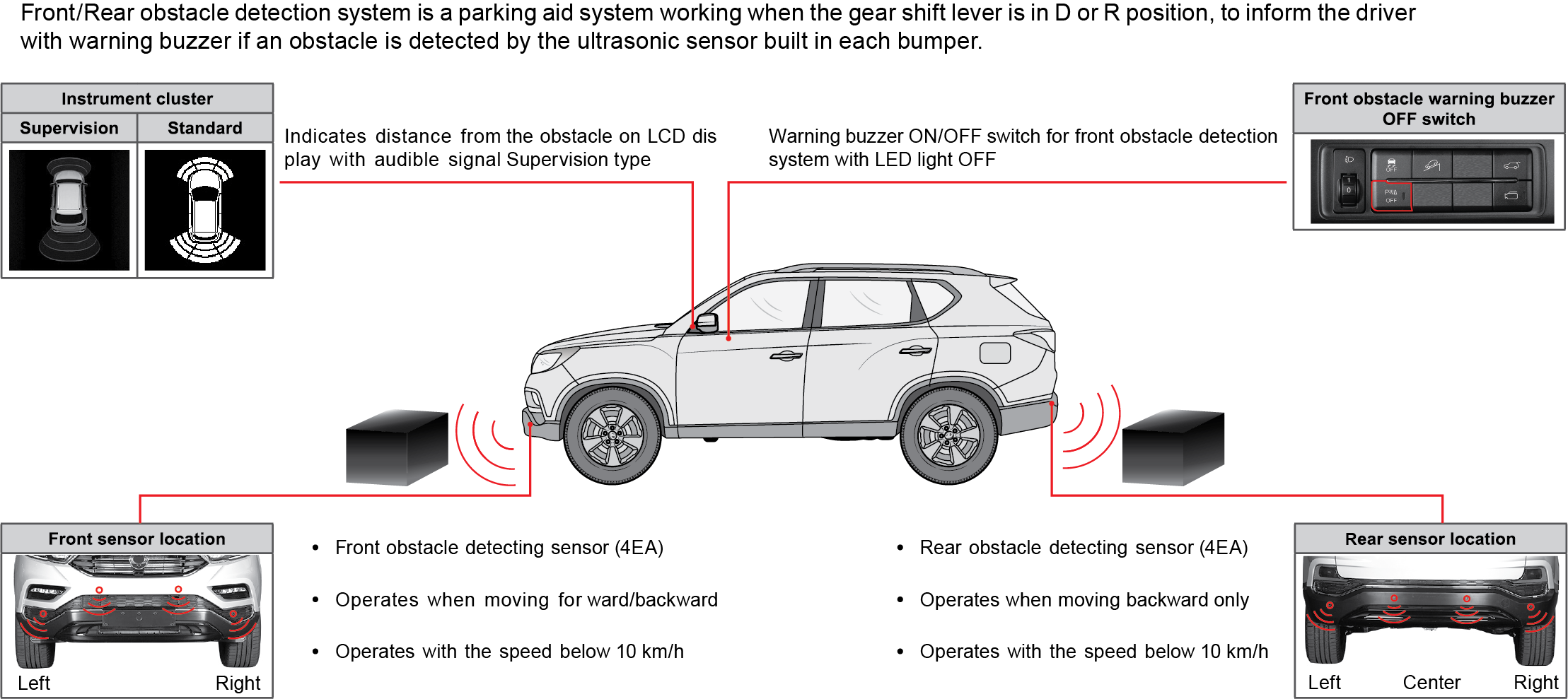
4.21 Parking Assist System - I (Rearview Camera System) (if equipped)

The monitor shows the view behind the vehicle when the gear selector lever is in R position.
| • | The actual distance may differ from what you see from the monitor because the rearview camera uses a wide-angle lens to have a large clear view. Therefore, you should check the rearview mirrors and the area behind the vehicle before and while moving backward |
| • | The rearview camera does not show the entire area behind the vehicle |
| • | Keep the camera lens clean using a camera lens cleaner so that the lens is free of foreign matter |
Rearview Camera
The rearview camera system is a supplementary function for safe driving to display the condition behind the vehicle while
the gear selector lever in R position.

Rearview Monitor
The rearview monitor is applied depending on the vehicle specifications.

4.22 Parking Assist System — II (if equipped) (Around View Monitoring System)
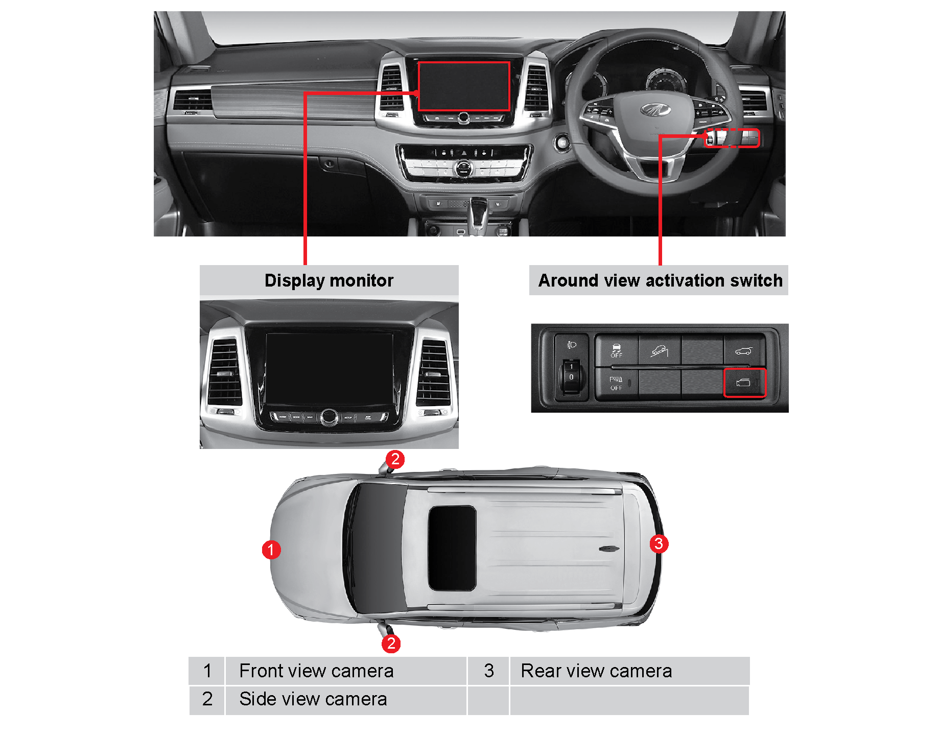
The AVM (Around View Monitoring) system is a parking assist system which facilitates parking by helping the driver see objects
around the vehicle. The system is activated when the interior switch is set to ON (indicator ON).
This system uses the 4 outside cameras and displays the information received from the cameras on the display. The driver can
see the outside of the vehicle in the desired direction by using the 3D view, if needed.
AVM : Around View Monitoring system.
4.22.1 Activation Conditions
The AVM system is activated when the following conditions are met:
| • | Ignition switch ON or engine running |
| • | Vehicle speed: less than 20 km/h |
| • | Gear selector lever in P, R, N, or D position |
| • | Around view activation switch ON (AVM is activated regardless of switch ON/OFF when gear selector lever is in R position) |
| • | Gear selector lever in R: AVM system is activated |
| • | Gear selector lever in P: AVM system can be activated but the previous screen is displayed on the display |
| • | The AVM system is a parking assist system |
| • | This system displays the combined images from the 4 cameras. Therefore, the displayed image may be different from the actual vehicle position and parking guideline, etc. Always park the vehicle by checking your vehicle's mirrors and glancing over your shoulder |
| • | Foreign materials on the camera lens can cause system error. Keep the lens surface clean |
4.22.2 About AVM
| • | The AVM system is optional |
| • | This system uses the 4 outside cameras and displays the images of front, left, right, rear regions of the vehicle. |
4.22.3 AVM Settings
Press button to go to the setup screen.
 |
|
4.22.4 Front AVM Operation (if equipped)
 |
Turn the ignition ON and press the AVM switch with gear selector lever in the N or D position to operate the front AVM system.
|
| • | PAS information display: Information of objects detected in the area in front of or behind the vehicle |
| • | Front view camera screen: Image from front view camera is displayed |
| • | Left view camera screen: Image from left view camera is displayed |
| • | Right view camera screen: Image from right view camera is displayed |
| • | Full front view image/3D view: |
| • | In 2D mode, full front view image is displayed |
| • | In 3D mode, full 3D view is displayed |
| • | Settings screen: Goes to AVM settings menu |
| • | When the front AVM is activated, driving at a speed of about 20 km/h or more deactivates the AVM. If this is the case, the AVM system remains deactivated even if the vehicle speed goes below 20 km/h |
| • | The AVM system uses wide angle cameras to provide the driver a wider field of view. Because of the wide angle lens, there is a slight difference between the distance displayed on the screen and actual distance. Always check your vehicle's mirrors and glance over your shoulder for safety |
4.22.5 Rear AVM Operation
Turn the ignition ON and move the gear selector lever to the R position to operate the rear AVM system.

|
The AVM system uses wide angle cameras to provide the driver a wider field of view. Because of the wide angle lens, there
is a slight difference between the distance displayed on the screen and actual distance. Always check your vehicle's mirrors
and glance over your shoulder for safety.
5 CONVENIENCE SYSTEM I
5.1 Using Smart Key
Smart key is a device which is designed to lock/unlock the doors and start the engine by just carrying it.
Also, the common functions of the remote control key are available by using the buttons on the smart key.
5.1.1 Short Press of Lock Button (Locking Doors)
| • | All doors and the tailgate are locked and the theft deterrent system is armed |
| • | The outside rearview mirror is folded automatically (outside rearview mirror folding/unfolding switch is not pressed) |
| • | The hazard warning lamp flashes twice and buzzer sounds once as soon as the theft deterrent is armed |
Refer to "Outside rearview mirror control switch" in Chapter 4 for details about setting the outside rearview mirror AUTO
folding/unfolding control.
| • | All doors including the tailgate and engine hood should be closed to arm the theft deterrent system. Locking the doors using the smart key with the tailgate and engine hood open only locks the doors and does not arm the theft deterrent system. If you close the tailgate or engine hood after locking the doors with a smart key, the hazard warning lamp flashes twice and buzzer sounds once signifying that the theft deterrent system is armed |
| • | Locking the door with door LOCK button on the smart key is not possible when the ignition switch is in ACC/ON position or the engine is running |
 |
 |
5.1.2 Long Press of Lock Button (Closing Windows)
| • | You can close the windows by using the door LOCK button on the smart key |
| • | When the door LOCK button is pressed and held, the theft deterrent system is armed and the windows move to the fully closed position as long as the button is pressed |
| • | When the door LOCK button is released, the windows stop moving. The windows continue to move when the button is pressed again |
| • | This window close function is activated when the door is equipped with window safety function and the corresponding vehicle system settings are set (Instrument cluster User settings menu > Door/Tailgate > Window open / close by smart key > Tick the checkbox) |
| • | A vehicle with Low Version Smart key doesn’t offer window close function by smartkey |
| • | Low Version Smart Key : Passive Entry by Door Handle Trigger Switch : X
Passive Start by Start Switch : O
|
| • | Perform this remote control operation in a place where you can see the windows of the vehicle for safety reasons |
| • | However if multiple attempts are made then the system is deactivated for the safe operation of the vehicle. The function is available when the ignition is turned OFF and then ON again |
 |
 |
5.1.3 Short Press Of Unlock Button (Safety Unlock Disabled)
| • | The doors including the tailgate are unlocked and the theft deterrent system is disarmed |
| • | The outside rearview mirror is unfolded automatically (outside rearview mirror folding/unfolding switch not pressed) |
| • | The hazard warning lamp flashes once and buzzer sounds twice signifying that the theft deterrent is disarmed |
Refer to "Outside rearview mirror control switch" in Chapter 4 for details about setting the outside rearview mirror AUTO
folding/unfolding control.
5.1.4 Short Press Of Unlock Button (Safety Unlock Enabled)
| • | Pressing the door UNLOCK button once briefly unlocks the driver door only and disarms the theft deterrent system. Refer to [Figure 1] |
| • | Pressing the door UNLOCK button again with the driver door unlocked unlocks all doors including the tailgate. Refer to [Figure 2] |
| • | Pressing the door UNLOCK button twice in a row unlocks the driver door first and then other doors, and disarms the theft deterrent system |
| • | The hazard warning lamp flashes once and buzzer sounds twice signifying that the theft deterrent is disarmed |
|
Driver Door Unlocked |
All Doors Unlocked |
 |
 |
|
Pressing UNLOCK button once with all doors locked and theft deterrent armed |
Pressing UNLOCK button once again with driver door unlocked |
How to Set Safety UNLOCK System
Instrument cluster User settings menu > Door/Tailgate > Unlock with key in 2 stages (safety UNLOCK) > Tick the check box
5.1.5 Long Press Of Unlock Button (Opening Windows)
| • | You can open the windows by using the door UNLOCK button on the smart key |
| • | When the door UNLOCK button is pressed and held, the theft deterrent system is disarmed and the windows move to the fully open position as long as the button is pressed |
| • | When the door UNLOCK button is released, the windows stop moving. The windows continue to move when the button is pressed again |
| • | This window open function is activated when the door is equipped with window safety function and the corresponding vehicle system settings are set (Instrument cluster User settings menu > Door/Tailgate > Window open/close by smart key > Tick the checkbox) |
| • | A vehicle with Low Version Smart key doesn’t offer window open function by smartkey |
| • | Low Version Smart Key : Passive Entry by Door Handle Trigger Switch : X
Passive Start by Start Switch : O
|
| • | Perform this remote control operation in a place where you can see the windows of the vehicle for safety reasons |
| • | However if multiple attempts are made then the system is deactivated for the safe operation of the vehicle. The function is available when the ignition is turned OFF and then ON again |
 |
 |
5.1.6 Tailgate Button (Type A)
| • | For vehicles with power tailgate |
| • | Pressing the switch briefly deactivates the power tailgate operation |
| • | Pressing and holding the switch activates the power tailgate AUTO open/close operation |
| • | The tailgate can be opened when you enter the area within a 1-metre radius from the Centre of the tailgate while carrying the smart key |
Refer to "Tailgate operation" for details about using the tailgate button.
5.1.7 Panic Button (Type B)
| • | For vehicles without power tailgate |
| • | Pressing and holding the button makes the hazard warning lamps flash and buzzer sound for 30 seconds |
| • | To deactivate the theft deterrent alarm, press and hold the panic button again |
 |
 |
|
Button name |
Short press |
Long press |
||
|
Front doors with safety window |
Press front doors with safety window all doors with safety window |
|||
|
Locking door |
Locking door |
Front door windows close control |
All door windows close control |
|
|
Unlocking door |
Unlocking door (When safety UNLOCK is enabled, only driver door is unlocked) |
Front door windows open control |
All door windows open control |
|
|
Type A |
Tailgate |
Deactivation |
Power tailgate operation (open/close) |
|
|
Type B |
Panic |
Panic (ON/OFF) |
||
| • | The safety function for power window may be applied to only 2 front doors or all 4 doors depending on the model |
| • | The power window with safety function offers AUTO UP/DOWN control |
| • | To prevent the smart key from being damaged, avoid places with a high temperature and high humidity |
| • | Always check that locked status of the doors and tailgate after locking the doors with the smart key. If the doors are not locked, the vehicle itself or your personal belongings in the vehicle can be stolen |
| • | If a key is lost, you cannot open the doors of the vehicle or start the engine. If you don't have a spare key, take the vehicle to a Mahindra Authorised Service Centre by towing it and have the vehicle serviced. Also, take the appropriate action to prevent your car and belongings from being stolen |
| • | Always check if the ignition switch is in OFF position and you are carrying a registered smart key after exiting your vehicle |
| • | Carry only one smart key |
| • | If the smart key which was last used is inside the vehicle and the vehicle is locked with another registered key, the door is locked properly but you cannot use the key inside the vehicle until the next start up. This is a safeguard against theft |
5.2 Additional Functions of Smart Key (if equipped)
5.2.1 Smart Door Auto Lock (Auto Close)

If you move a certain distance away from the vehicle while carrying a smart key with all doors including tailgate closed,
all doors including tailgate will be locked and the theft deterrent system will be armed.
If you stay in the key detection area for 1 minute. or more under the same conditions, the AUTO lock function is activated
for theft protection.
The hazard warning lamp flashes twice and buzzer sounds once as soon as the theft deterrent is armed.
| • | The smart door AUTO lock function can be enabled/disabled under "User settings menu → Functions for driver comfort" |
| • | Refer to "Outside rearview mirror control switch" in Chapter 4 for details about setting the outside rearview mirror AUTO folding/unfolding control |
| • | A vehicle with Low Version Smart key doesn’t offer Smart Door Auto Lock function |
| • | Low Version Smart Key : Passive Entry by Door Handle Trigger Switch : X
Passive Start by Start Switch : O
|
| • | The detection of smart key can vary depending on the walking speed and surrounding environment |
| • | When using the smart door AUTO lock function, always check the locked state of the doors and tailgate after seeing the flash of hazard warning lamp (twice) and hearing a buzzer sound (once) |
| • | If there is any smart key left inside the vehicle, the smart door AUTO lock function will not be activated |
| • | When the smart key battery is fully depleted, the smart door AUTO lock function will be disabled automatically. Therefore, you should reset the vehicle setting in the instrument cluster after replacing the smart key battery. |
5.2.2 Approach (Auto) Lamp

Welcome Mode
When approaching the door handle of the vehicle while carrying a smart key with the theft deterrent armed, the approach lamp
is turned ON (AUTO approach function).
| • | A vehicle with Low-Version Smart key doesn’t offer Welcome mode when approaching door |
| • | Low Version Smart key : Passive Entry by Door Handle Trigger Switch : X
Passive Start by Start switch : O
|
Goodbye Mode
If the driver door is opened after turning the ignition switch from ON to OFF, the approach lamp will be turned on.
Approach Lamp OFF (Welcome & Goodbye Mode)
The approach lamp is turned off when the approach lamp stays on for more than 30 seconds,., theft deterrent is armed, smart
door AUTO lock signal is received, and IGN is turned ON.
The welcome mode can be activated 30 seconds,. after the theft deterrent system is armed.
AUTO approach function is activated up to twice for 10 minutes
 |
 |
5.2.3 Door Outside Handle Switch Lock (if equipped)
| 1. | Stay in a vehicle outside antenna area (within approx. 1.5 m) while carrying a smart key with all doors including the tailgate are closed. |
| 2. | Press on the door LOCK/UNLOCK button on the front/rear door outside handle. |
| 3. | The hazard warning lamp flashes twice and buzzer sounds once signifying that all doors including the tailgate are locked. (Theft deterrent system is armed.) |
Pressing the LOCK/UNLOCK button does not lock the doors in the following cases:
| • | When trying to lock the door with the smart key in the cabin |
| • | Ignition switch in ACC/ON or engine running |
| • | Any door is open |
| • | Always check if the ignition switch is in OFF position and you are carrying a registered smart key after exiting your vehicle |
| • | Carry only one smart key |
| • | If the smart key which was last used is inside the vehicle and the vehicle is locked with another registered key, the door is locked properly but you cannot use the key inside the vehicle until the next start up. This is a safeguard against theft |
5.2.4 Door Outside Handle Switch Unlock (Safety Unlock Disabled)
| 1. | Stay in a vehicle outside antenna area (within approx. 1.5 m) while carrying a smart key. |
| 2. | Press on the door LOCK/UNLOCK button on the front/rear door outside handle. |
| 3. | The hazard warning lamp flashes once and buzzer sounds twice signifying that all doors including the tailgate are unlocked. Pull the lever to open the door. |
If the doors are unlocked by using this function, anyone within the smart key actuation area can open the doors. Be aware
of the theft.
5.2.5 Door Outside Handle Switch Unlock (Safety Unlock Enabled)
Press on the driver door outside handle switch with system settings are set [Instrument cluster User settings menu > Door/Tailgate
> Unlock with key in 2 stages (safety UNLOCK) > Tick the checkbox].
| 1. | Press on the driver door outside handle switch while carrying a smart key. |
| 2. | Only the driver door is unlocked and the theft deterrent system is disarmed. |
| 3. | The hazard warning lamp flashes once and buzzer sounds twice. |
| 4. | Press on the driver door outside handle switch within 4 seconds,. |
| 5. | The hazard warning lamp flashes once and buzzer sounds twice signifying that all doors including the tailgate are unlocked. |
Pressing the door handle switch on the doors other than the driver door unlocks all doors even if the safety UNLOCK is enabled.
If the driver door outside handle switch is pressed 4 seconds,. after the driver door is unlocked, all doors will be locked
and the theft deterrent system will be armed.

5.3 Cautions For Using Smart Key
5.3.1 Cautions
| • | If you lock the doors by pressing the door lock button on the door outside handle or smart key from outside the vehicle with another smart key inside the cabin, the smart key functions available just by carrying it including the remote control function will be disabled temporarily (buzzer sounds). To restore the functions, disarm the theft deterrent system by pressing the button on the door outside handle or smart key |
| • | If the engine is not started with a smart key inside the cabin or being carried, start the engine by putting the smart key against the ignition switch and pushing to operate the switch |
| • | The smart key may not function if the vehicle is in an area which has strong electric waves or noise, the vehicle is equipped with a third-party two-way radio/transmit-receive device, or a smart key for nearby vehicle is used |
| • | If a smart key is located near the accelerator/brake pedal, on the vehicle floor or seat cushion, the key may not be detected. If this is the case, carry the smart key in your pocket or put the key in a different location in the cabin |
| • | Additional smart keys on the same key chain may cause key related fault and engine starting failure |
| • | Therefore, the smart keys should be stored separately, and no smart keys should be in the cabin when the vehicle doors are locked by lock button on the door outside handle |
| • | If a smart key is in the cabin, you can start the engine by pressing the ignition switch with the brake pedal depressed. Do not leave other persons who don't know about the system, especially children, with a smart key inside the parked vehicles. The engine may be started accidentally or the vehicle can be controlled incorrectly. This could result in a serious accident |
| • | When you leave the vehicle even for a very short time, always turn the ignition off, carry the smart key in your pocket, and do not leave the spare key inside the vehicle. Otherwise, the vehicle including valuables can be stolen or malfunctions may occur |
| • | Make sure that water or liquid does not enter the smart key. Failure to do so can lead to smart key failure and this failure will not be covered by warranty |
| • | If a key is lost, you cannot start the engine. Contact the nearest Mahindra Dealer |
5.4 Immobiliser System
The immobiliser System provides an additional theft deterrent to the vehicle in which it is installed and prevents it from
being started by unauthorised persons. The transponder integrated in the key and the engine control unit have the same code.
When the ignition key with the integrated transponder is turned to the ON position, the ECU (Engine Control Unit) checks the
crypto code of the key and, if correct, allows your vehicle to start the engine.

Immobiliser Key
When the ignition key with the integrated transponder is turned to the ON position, the ECU (Engine Control Unit) checks the
crypto code of the key and, if correct, allows your vehicle to start the engine.
| • | Avoid impact to the transponder inside of the key. The transponder could be damaged |
| • | With a damaged transponder, the engine cannot be started |
| • | Do not instal any metal object near the ignition switch and on the remote control key. Otherwise, they may disturb the signal between ignition switch and remote control key and result in engine starting problem |
The time needed for communication between the immobiliser key and ECU can vary. If it is very short, the immobiliser indicator
does not come on.
| • | In addition, any remote engine starter cannot be installed to the vehicle equipped with the immobiliser system. So never instal any remote engine starter |
| • | The immobiliser system should be inspected, replaced, serviced, or coded by only qualified service personnel in a Mahindra Dealer or Mahindra Authorised Service Centre |
| • | When an old code should be replaced or another key is added, please observe the process personally |
| • | If you fail to start the engine due to the reason (ex, key chain) other than key itself, remove the key from the ignition switch and wait for around 10 seconds. And, try to start the engine again |
In any case, the immobiliser system cannot be removed from the vehicle. Do not attempt to alter this system or add other device
to it. Electrical problems could result that may make your vehicle inoperable.
5.4.1 Engine Does Not Start Due To Communication Error
If there is a communication error in immobiliser system, you cannot start the engine. In this case, the immobiliser indicator
in meter cluster blinks.
In the following cases, you may be unable to start the vehicle with the immobiliser:
| • | When two or more immobiliser keys come into contact with (each) other(s) |
| • | When the key is close to any device sending or receiving electromagnetic fields or waves |
| • | When the key is close to any electronic or electric devices such as lighting equipment, security keys or security cards |
| • | When the key is close to a magnetic or metal object or a battery |
| • | When you start the engine before completing the pre-glow process |
| • | If you fail to start the engine due to the communication error or early start before completion of pre-glow, clear the reason and wait for around 10 seconds. And, try to start the engine again |
| • | If the indicator remains blinking, have the immobiliser system checked by a Mahindra Dealer or Mahindra Authorised Service Centre |
When the Transponder is Damaged
When the transponder is damaged, you must replace it with a new one and register a new code on the engine control unit at
Mahindra Dealer or Mahindra Authorised Service Centre. Otherwise, the engine cannot be started.
When You Lost The Key
When you lost the key, the encrypted code should be removed from the Engine Control Unit to avoid any vehicle theft. Please
contact Mahindra Dealer or Mahindra Authorised Service Centre.
5.5 Theft Deterrent System
The theft deterrent system is activated when locking the doors using the remote control key or smart key. When somebody tries
to open the door, tailgate or engine hood with any other way other than using remote control key or smart key, the hazard
flashers blink and the siren sounds.
5.5.1 Arming The Theft Deterrent System
| • | When locking the vehicle with remote control key or smart key (including lock button on door handle), the anti-theft mode
will be activated Remote control key: When the theft deterrent system is armed, the hazard flashers blink twice. However, if you press this button once again in
4 seconds, the hazard flashers blink twice and the buzzer sound once.
Smart key: When the theft deterrent system is armed, the hazard flashers blink twice and the buzzer sound once.
|
| • | If a door is not opened within 30 seconds after unlocking the doors with remote control key or smart key in theft deterrent mode, all doors will be automatically locked again (back to theft deterrent mode) |
| • | If you lock the doors using key hole in door, doors will be locked but the theft deterrent mode will not be armed |
Smart key: To arm the theft deterrent system, the ignition key should be in {OFF} or {ACC} position and all doors including the tailgate
and the engine hood should be closed completely.
If the ignition switch is in {ACC} position, the switch will be automatically changed to {OFF} position when arming the theft
deterrent mode.
When the ignition switch is in {ON} position, the theft deterrent mode cannot be activated.
5.5.2 Alarm
If somebody tries to open the door, the tailgate or the engine hood without using the remote control key or smart key, the
alarm will be activated:
| • | When one of the doors or the tailgate is opened with the ignition key while the deterrent system is armed, the alarm will be activated |
| • | The engine hood or the tailgate is opened from the outside while the deterrent system is armed, the alarm will be activated |
| • | When the alarm is activated, the buzzer sounds and the hazard flashers will blink for 30 seconds |
| • | The alarm stops when (while keeping theft deterrent mode): Remote control key: Pressing “Lock”, “Unlock”, “Panic” button on the remote control key, or turning the ignition switch to
“ON” position
Smart key: Pressing “Lock” or “Unlock” button on the Smart key, pressing the “Lock/Unlock” button on the outside door handle,
or turning the ignition switch to “ON” mode by pressing it.
|
5.5.3 Deactivating The Alarm
The alarm does not activate when:
| • | Opening the tailgate with “Tailgate Open” button on the smart key |
| • | Opening the tailgate by pressing the “Open” switch behind the tailgate door handle |
All doors except tailgate are still in the theft deterrent mode, and the tailgate returns to the theft deterrent mode again
when closing it.
5.5.4 Disarming The Theft Deterrent Mode
| • | The theft deterrent mode will be disarmed when unlocking the doors with remote control key or Smart key (including “Lock/
Unlock switch on outside door handle) Remote control key: When the theft deterrent system is disarmed, the hazard flashers blink once.
Smart key: When the theft deterrent system is disarmed, the hazard flashers blink once and the buzzer sound twice.
|
| • | If a door is not opened within 30 seconds after unlocking the doors with remote control key or smart key in theft deterrent mode, all doors will be automatically locked again (back to theft deterrent mode) |
5.6 Tailgate Switch

5.6.1 Switch Configuration Depending On Power Tailgate Installation
|
Item |
With Power Tailgate
(if equipped) |
Without Power Tailgate |
|
1 |
Tailgate interior switch |
Not available |
|
2 |
Tailgate outside switch |
← |
|
3 |
Tailgate inside switch |
Not available |
|
4 |
Smart key tailgate button |
Smart key panic button |
|
5 |
Smart tailgate open |
Not available |
| • | For vehicles with power tailgate, the tailgate can be opened/closed automatically by simple switch operation |
| • | The power tailgate can be operated only when the gear selector lever is in the P position. If the ignition is turned OFF, then it can be operated regardless of the gear selector lever position |
Do not operate the power tailgate manually if at all possible. If it needs to be operated manually because of malfunction,
do not apply excessive force to the power tailgate. The power tailgate mechanism can be damaged
The power tailgate moves up when it is opened. Always check the inside or outside of the vehicle when opening or closing the
tailgate for safety. Be careful so that your face or head is not struck by the moving tailgate or hands or feet are not trapped
by the closing tailgate.
5.7 Tailgate Operation (Without Power Tailgate)
5.7.1 Tailgate Open

| • | Stay in a tailgate antenna area (within approx. 1 m) while carrying a smart key |
| • | Press the tailgate open switch on the inner side of the tailgate door handle. Only the tailgate will be unlocked |
| • | Open the tailgate by lifting it up |
5.7.2 Tailgate Close

| • | Pull the tailgate down by grabbing the inner handle |
| • | Slightly push the lowered tailgate to close it completely |
When only the tailgate is opened and closed with the theft deterrent system armed, the hazard warning lamp flashes twice and
buzzer sounds once signifying that the theft deterrent system is re-armed.
If the tailgate is opened and closed with the theft deterrent system disarmed, the door LOCK button on the smart key should
be pressed to arm the theft deterrent system.
| • | Always check your surroundings before opening or closing the tailgate for safety |
| • | Be careful not to let any part of your body such as your hand get caught by accident when closing the tailgate |
| • | Close the tailgate as carefully as possible to avoid injury because the tailgate can be closed abruptly by its own weight or by outside factors |
5.8 Power Tailgate Operation (if equipped)
5.8.1 Power Tailgate Open

| • | Pressing and holding the tailgate interior switch with the tailgate closed opens the power tailgate after 2 blinks of hazard warning lamp and 2 beeping sounds |
| • | Pressing the switch during power tailgate operation stops the tailgate operation. Pressing and holding the switch again reverses
the direction of tailgate movement |
| • | Pressing and holding the tailgate outside switch with the theft deterrent armed while carrying a smart key opens the power tailgate after 2 blinks of hazard warning lamp and 2 beeping sounds |
Performing this function with the theft deterrent system armed disarms only the power tailgate.

| • | Pressing and holding the tailgate button on the smart key opens the power tailgate after 2 blinks of hazard warning lamp and 2 beeping sounds |
| • | Pressing the tailgate button during power tailgate operation stops the tailgate operation. Pressing and holding the tailgate button again reverses the direction of tailgate movement |
| • | The power tailgate can be opened automatically with ignition switch ON and gear selector lever in the P position |
| • | The power tailgate cannot be opened automatically with ignition switch ON and the vehicle speed of 4 km/h or more |
| • | If you carry the key in your pocket, be careful that the key may be pressed unintentionally, which causes the power trunk to be open |
5.8.2 Power Tailgate Close
| • | Pressing and release the tailgate interior switch with the tailgate open closes the power tailgate after 2 blinks of hazard warning lamp and 2 beeping sounds |
| • | Pressing the switch during power tailgate operation stops the tailgate operation. Pressing and holding the switch again reverses
the direction of tailgate movement |
| • | Pressing and release the tailgate inside switch with the tailgate open closes the power tailgate after 2 blinks of hazard
warning lamp and 2 beeping sounds |
| • | Pressing and holding the tailgate button on the smart key closes the power tailgate after 2 blinks of hazard warning lamp and 2 beeping sounds |
| • | Pressing the tailgate button during power tailgate operation stops the tailgate operation. Pressing and holding the tailgate button again reverses the direction of tailgate movement |
If the power tailgate (Cinching motor) is operated 5 times consecutively, the drive motor of the power tailgate (spindle part)
may be under strain. The power tailgate stops operating after 3 warning buzzer sounds to protect the motor from overheating.
If this is the case, wait for 1 minute. or more before operating the tailgate again.
| • | Closing the tailgate urgently within a very short time may be difficult. This is not a fault. Try to close the tailgate after a while |
| • | Remove any obstacles inside or outside the vehicle around the tailgate path before closing the tailgate |
| • | The power tailgate can be operated with ignition switch turned OFF. With extended use, the power tailgate may wear down your battery |
| • | Do not apply excessive force to the tailgate during power tailgate operation. The power tailgate may be damaged |
| • | Do not operate the power tailgate with heavy objects attached to it. The power tailgate may be damaged |
| • | Never modify or attempt to repair any of the power tailgate parts |
| • | Do not operate the power tailgate if one wheel of the vehicle is lifted up by a jack for tyre rotation or vehicle service, a wheel of the vehicle is off the ground because of uneven road surface, or the vehicle is parked on a very hilly terrain. The power tailgate may have a malfunction |
| • | If the vehicle is driven at 4 km/h or more with the tailgate open, warning buzzer sounds 10 times. In this case, stop the car in a safe location as soon as possible and close the tailgate securely. Make sure that the tailgate open warning on the instrument cluster is deactivated before driving off |
| • | Do not drive the vehicle with the tailgate open and cargo sticking out the back of the vehicle. This may endanger other road users behind your vehicle or can damage the vehicle body or components related to the tailgate |
| • | If the tailgate is opened with the vehicle parked on a hill, cargo may fall out of the vehicle causing serious personal injury |
| • | A child holding a smart key can operate the power (smart) tailgate accidentally, causing personal injury or damage to the vehicle including objects around the tailgate |
| • | Be careful not to let any part of your body such as your hand get caught by accident when closing the tailgate |
| • | Close the tailgate as carefully as possible to avoid injury because the tailgate can be closed abruptly by its own weight |
| • | Driving with the tailgate open can draw exhaust gases into the cabin resulting in carbon monoxide poisoning, let the cargo fall out of the vehicle, or cause accidents. Be sure to close the tailgate securely before driving |
5.8.3 Anti-Pinch Protection
If a severe impact or constant force is applied from outside the vehicle during the power tailgate operation, the tailgate
stops moving or moves up to the fully open position automatically.
However, this anti-pinch protection function may not work in a certain part of the tailgate path where resistance force applied
is insufficient to change the movement direction or the tailgate is almost closed.
If the anti-pinch protection operation is repeated, open or close the tailgate manually to check if the tailgate operates
normally.
Do not put objects or part of your body in the tailgate path intentionally during power tailgate operation to check the anti-pinch
protection operation.
5.9 How To Set Power Tailgate (if equipped)
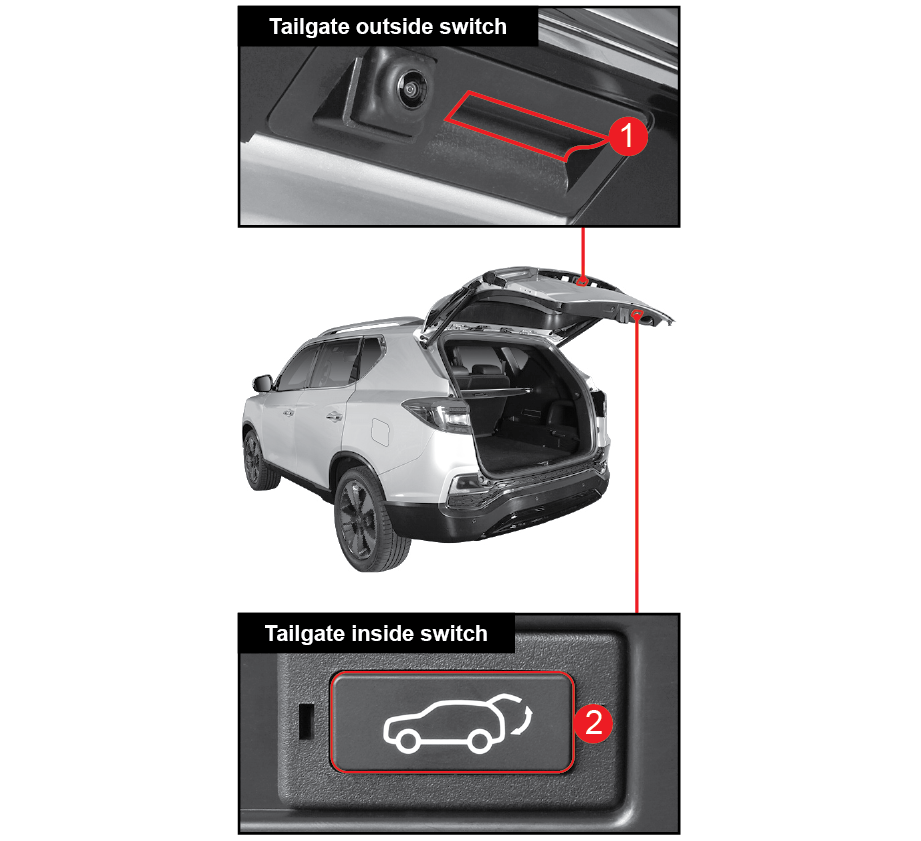
5.9.1 Re-Setting Open / Close Operation
Perform the following procedure to reset the power tailgate setting when the battery is fully depleted, the power supply is
reconnected, or the power tailgate does not function normally:
| • | Park the vehicle on a level ground and shift the gear selector lever to the P position |
| • | Press and hold the power tailgate outside switch (1) for 3 seconds,. or more while pressing the power tailgate inside switch (2) |
| • | A beep will be heard indicating that the resetting is completed |
| • | Close the tailgate completely by hand |
| • | Press the power tailgate switch to check the AUTO open/close operation |
If the power tailgate does not function properly even after the resetting procedures, contact a Mahindra Dealer or Mahindra
Authorised Service Centre.
5.9.2 Adjusting Opening Height
You can adjust the opening height of the power tailgate as desired:
| • | Open the power tailgate manually to the desired position |
| • | Press and hold the power tailgate inside switch (2) for 3 seconds,. or more |
| • | A beep will be heard indicating that the adjusting is completed |
| • | Press the power tailgate switch to close the tailgate automatically until it is fully closed |
| • | Press the power tailgate switch again to check if the tailgate is opened to the set position |
5.10 Smart Tailgate Operation (if equipped)
5.10.1 Smart Tailgate
The smart tailgate is a comfort function which opens the tailgate automatically when a user carrying a smart key is approaching
the vehicle:
| • | The smart tailgate function can be enabled/disabled under "User settings menu → Door/Tailgate" |
| • | When the smart tailgate is enabled, the smart tailgate indicator comes on the LCD screen of the instrument cluster |
Deactivating Smart Tailgate
Pressing any button on a smart key (shown in the figure below) or moving out of the smart key beyond detection area during
the smart tailgate operation deactivates the function immediately.

| • | The smart tailgate operation may be delayed or the operation distance may change in the following situation because of frequency
interference: When you are in an area near a facility which emits strong radio frequencies, such as police stations, public offices, broadcasting
stations, military facilities, transmitting towers, airports, harbours..
When you are carrying a smart key along with a cell phone.
|
| • | The size of the smart key detection area may change if one wheel of the vehicle is lifted up by a jack for vehicle service or the vehicle is parked on a very hilly terrain |
| • | Familiarise yourself with deactivation of the smart tailgate for emergency |
| • | Disable the smart tailgate operation before washing the vehicle. Otherwise, the tailgate can be opened accidentally during washing |
| • | The tailgate will be opened automatically whenever you are in the smart key detection area with a smart key |
5.10.2 Smart Tailgate Open

If you stay in the tailgate antenna area (within a 1-metre radius from the backside of the vehicle) for 3 seconds,. or more
while carrying a smart key with the theft deterrent system armed, the smart tailgate is activated along with the alarm in
the following stages:
Stage 1 - Detection warning
Hazard warning lamp flashes once and buzzer sounds once at 1 second. intervals for 0.5 second. (beep-, beep-, beep-)
Stage 2 - Detection warning
Hazard warning lamp flashes 3 times and buzzer sounds 3 times (beep, beep, beep)
Stage 3 - Open warning
Hazard warning lamp flashes twice and buzzer sounds twice after smart tailgate is ready to be opened (beep, beep)
The smart tailgate is activated 30 seconds,. after the theft deterrent system is armed to avoid malfunctions of the smart
tailgate system.
After a smart key is detected, the hazard warning lamp flashes twice and the warning buzzer sounds twice signifying that the
smart tailgate is activated, and then the tailgate is opened.

Press the button on the smart key to deactivate the smart tailgate.
5.10.3 Safety Release Lever
Your vehicle is equipped with the emergency tailgate safety release lever located on the bottom of the tailgate. When someone
is inadvertently locked in the luggage compartment.
You can open the tailgate inside vehicle.
| • | Open the cover |
| • | To unlock the tailgate, push the emergency safety release lever inside the trim panel to right side. |
| • | Push the tailgate to open. |
 |
 |
| • | Use the release lever for emergencies only. Use extreme caution, especially while the vehicle is in motion |
| • | For emergencies, be fully aware of the location of the emergency tailgate safety release lever in this vehicle and how to open the tailgate if you are accidentally locked in the luggage compartment |
| • | Do not allow children to play in cargo area. If they open the tailgate with the opening lever abruptly, it may cause a serious personal injury |
| • | No one should be allowed to occupy the luggage compartment of the vehicle at any time. The luggage compartment is a very dangerous location in the event of a crash |
5.11 Door Open Lever, Lock/Unlock Knob And Switch
 |
|
Children in rear seats can open rear doors. Move the child-safe lever to (LOCK) position.
|
5.11.1 Door Lock/Unlock Switch

If the door LOCK/UNLOCK switch (push self-return type) is pressed with all doors including the tailgate locked, the door state
is changed between unlocked and locked every time the switch is pressed.
| • | The vehicle cannot be locked when any of the doors is open with any method (door lock knob, door lock/unlock switch, remote control key, Smart key) |
| • | This switch is not available when any of the doors are not fully closed and the vehicle is in theft deterrent mode |
| • | The options for door AUTO lock function can be selected under “Instrument cluster User settings menu → Door/Tailgate”. (OFF / When driving / When shifting to R, N, D) |
| • | The options for door AUTO unlock function can be selected under “Instrument cluster User settings menu → Door/Tailgate”. (OFF / When IGN OFF / When shifting to P) |
| • | Always check that all doors including tailgate are securely locked before driving off. Opening a door during driving, especially by children, may cause a serious accident |
| • | Even though all doors are locked, they will be automatically unlocked when opening the driver’s door. Opening the driver’s door may cause a serious accident. Pay particular attention not to open the door during driving |
| • | When getting off, check the rear and side of the car for passing vehicles or pedestrians. Vehicles or motorcycles coming from the rear, if unchecked, might stumble on you when you open the door |
| • | Never leave infants and children unattended in the vehicle with the doors locked. They can be suffocated in especially hot weather |
5.12 Opening And Closing Windows

|
1 |
Passenger door window switch (AUTO) |
4 |
Driver door window switch (AUTO) |
|
2 |
Rear left door window switch (AUTO) |
5 |
Rear right window switch (AUTO) |
|
3 |
Door LOCK/UNLOCK |
6 |
Window LOCK switch |
5.12.1 Door LOCK/UNLOCK Switch
The door (including fuel filler door) state is changed between locked and unlocked each time the switch is pressed.
5.12.2 Window LOCK Switch
Pressing the switch changes the door window state as follows:
| • | Driver side: Windows of all doors open/close operation available |
| • | Passenger side: Passenger door window open/close operation available |
| • | Rear left/right side: Rear left/right windows open/close operation not available |
When closing the windows of other doors by operating the window switch on the driver door trim, make sure that any body part
of the occupants is not caught by the moving window.
When carrying children in the rear seats, press the window LOCK switch to prevent the children from operating the window switch.
5.12.3 Driver Door/Passenger Door Window Switch (AUTO) (if equipped)
To lift up/down the windows, the ignition should be turned ON or engine should be running. However, you can still open/close
the windows during delay time for window operation.
The window switch can be operated for 30 seconds,. after the ignition switch is turned from ON to ACC or OFF. If the front
door is opened, the window operation stops immediately.
To open the window
| • | To open the window to the desired position, gently press the front portion of the switch (not fully pressed). The window keeps moving as long as the switch is pressed in this way |
| • | Fully push down the front portion of the switch and then release it to open the window automatically. (AUTO down) |
| • | If you want to stop the window from going all the way down during AUTO down operation, lightly press the switch again or pull up the switch |
To close the window
| • | To close the window to the desired position, gently pull up the front portion of the switch (not fully pulled up). The window keeps moving as long as the switch is pulled up in this way |
| • | Fully pull up the front portion of the switch and then release it to close the window automatically. (AUTO up) |
| • | If you want to stop the window from going all the way up during AUTO up operation, lightly press the switch again or pull up the switch |
| • | If the window runs into any obstacle during AUTO up operation, it will reverse direction and then stop at the preset position |
| • | If you keep pulling up the front portion of the switch, the window will not reverse direction. This is a safety precaution to protect the driver from a criminal |
| • | Operating 2 window switches at the same time may blow the fuse or damage the window lifting device |
| • | If the window switch on the driver door and window switch on another door are operated at the same time in the opposite direction, the window lifting system may fail |
5.12.4 Second Row Seat Window Switch

You can open the window using this switch in the same way as the driver/passenger window AUTO switch is operated.

To move windows up or down, pull up or press the corresponding switch for the window.
| • | Before operating the power windows, make sure that nothing can be trapped (such as heads, hands, or fingers) in the window |
| • | Make sure that passengers do not stick out their hands or heads from the vehicle while driving |
5.12.5 Anti-Trap System For Driver’s Window
The anti-trap system enables the driver’s window to automatically reverse when something is caught in the window as it is
closing. When the sensor detects an obstacle, the window will be lowered immediately.

| • | The anti-trap safety system is available only for the driver’s window equipped with the automatic rolling up (AUTO-up) function |
| • | The anti-trap system does not operate where the space between top of the glass and window frame is very close |
| • | If the window is stuck in very cold weather, anti-safety function may work. In this case, fully close the window by switch |
5.13 Engine Hood
5.13.1 Opening The Engine Hood

| • | Pull the release lever (A) located on the lower right hand side of the steering wheel to unlatch the engine hood |
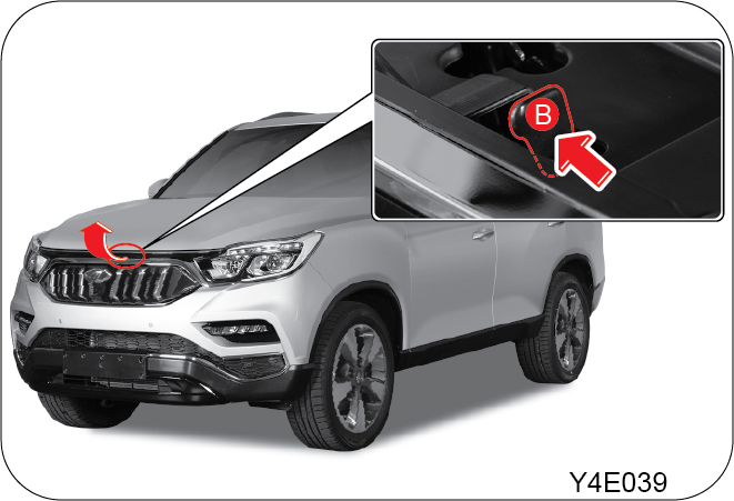
| • | Hold the engine hood slightly open to pull the safety latch lever (B) up using your fingers and lift up the engine hood completely |
5.13.2 Closing The Engine Hood
| • | Observe the following precautions before closing the engine hood |
| • | Make sure that all filler caps in the engine compartment are closed securely |
| • | Check that no service tools or items, such as gloves, screwdrivers, are left in the engine compartment |
| • | Slightly push the lowered engine hood to close it completely |
If the closed engine hood is lifted up, open the engine hood again and close the hood as hard as possible to close it securely.
| • | Make sure that your clothes or tools do not contact or tangle with any moving parts in the engine compartment when the hood is open with engine running |
| • | Check that the engine hood is fully latched in position by pulling at the front edge of the hood before driving |
| • | Be cautious about strong wind that may cause a sudden close of the engine hood, resulting in serious injuries |
| • | Do not check the engine compartment in an area where strong wind blows |
| • | Before closing the engine hood, ensure that none of your body parts are trapped |
5.14 Fuel Lid
5.14.1 Opening Fuel Lid

| • | Move the gear selector lever to the P position |
| • | Turn off the engine |
| • | Press on the Centre edge (B) of the fuel lid (A) with all doors unlocked |

| • | Pull the fuel lid (C) towards yourself to open it |
| • | Turn the fuel lid (D) counterclockwise to open it |
Stop the engine before refuelling

| • | Hang the fuel lid (D) on the holder (E) mounted on the inner side of the cover |
| • | After refuelling, turn the lid (D) clockwise until you hear a “click”, and close the cover (E) by pushing it back |
| • | Be careful not to allow the fuel to contact the painted surface of the body as it can damage the paint work |
| • | If the fuel lid is frozen shut in the winter, do not attempt to apply any excessive force on the fuel lid. Lightly tap on the edge of the door to open it |
| • | Use only genuine parts when replacing the fuel lid |
| • | To fill the tank completely, top up until the pump nozzle of the fuel supply gun stops working |
| • | Do not “top off” the fuel tank after filling to avoid fuel spillage and overflowing due to thermal expansion |
| • | Always pay attention when opening the fuel lid, as the fuel may be pressurised. If you hear a hissing sound with fuel leaks, wait until no sound is heard |
| • | Discharge any static electricity by touching any metal part which is at a safe distance away from the fuel filler with your bare hands before grabbing a fuel supply gun or touching fuel lid |
| • | Getting in and out of the vehicle during fuelling can cause fire due to charged static electricity. Do not get in or out of the vehicle during fuelling |
| • | When fuelling using a portable tank, make sure that the fuelling is carried out outdoors and the tank is on the ground during fueling. Fuelling with the portable tank placed on the vehicle or fuelling indoors can cause fire due to static electricity |
| • | Always stop the engine when refueling. Use only the designated fuel and low sulphur diesel |
| • | Always turn off the engine, do not use a lighter, and never have any smoking materials lit during fuelling for fire protection |
| • | If you add inappropriate grade fuel, fuel blended with water or improper fuel additives to the fuel tank, the fuel system and exhaust gas system may be seriously damaged |
| • | Always check the fuel to be used before filling the fuel tank. If a diesel-engine vehicle is misfueled with gasoline, the fuel system and other vehicle systems can be seriously damaged |
| • | Never use a cellular phone near a gas station. The electromagnetic field emitted from the cellular phone can cause fire |
5.15 Sunroof (if equipped)
5.15.1 Sunroof Switch
The sunroof cover opens and closes manually.

| • | Even though the sunroof can be operated when the ignition key is in the ON position (the engine is not running), operating the sunroof repeatedly with the engine turned off will run down the battery. Operate the sunroof while the engine is running |
| • | When a desired sunroof operation is completed, release the switch. If you keep pressing the switch, it could cause a malfunction. Especially in winter, never operate the sunroof if moving areas are iced. Wait until the areas are deiced |
| • | When leaving the vehicle unattended, be sure to completely close the sunroof. Otherwise, there is a great risk of vehicle theft. Or, the interior of the vehicle will be wet when it rains or snows |
| • | When the sunroof is slid to its complete open position, the wind buffet phenomenon can increase. If this happens, adjust by opening the sunroof or only open two-thirds of the sunroof by using only the first step of the opening system |
| • | When operating the sunroof, be aware of safety conditions before operation. Parts of the body can be trapped |
| • | Clean up the circumference of sunroof regularly. Otherwise, operating the sunroof may cause a noise due to foreign material and dirt |
| • | Opening the sunroof or driving with the sunroof open after a car wash or rain may lead to water entering |
| • | Close the sunroof while driving in the dusty environment. The dusts or particles entered can cause operating problems |
| • | If a roof rack system is installed on the vehicle roof or any cargo is secured to the roof rack, do not operate the sunroof. If you are required to operate the sunroof, carefully check that the roof rack system does not interfere with the sunroof and it is safe to open the sunroof |
| • | Make sure that no passenger sticks out head, hand or any part of his/her body out of the sunroof opening while driving. There is a risk of personal injury when the vehicle is stopped suddenly |
| • | Before operating the sunroof, make sure that no head, hand, finger, or any object is capable of being trapped. There is a risk of personal injury or even death |
5.15.2 Sunroof Sliding Operation

Open: 2-Step Opening
| • | Push up the switch briefly: 2-step auto sliding open When pushing up the sunroof switch briefly, the sunroof is automatically opened by two-third of its travel (first step). When pushing up and holding the sunroof switch again, the sunroof is completely opened (second step) |
| • | Push up and hold the switch: manual sliding open The sunroof is opened as long as pushing up the switch |
Close
| • | Pull down the switch briefly: auto sliding close When pulling down the sunroof switch briefly, the sunroof is automatically closed completely. To stop the sunroof, pull or push the switch at desired position while moving |
| • | Pull down and hold the switch: manual sliding close The sunroof is closed as long as pulling down the switch |
5.15.3 Sunroof Tilting Operation

Tilt Up
The rear side of the sunroof is tilted up when pulling down the sunroof switch with the sunroof closed.
Tilt Down
The rear side of the sunroof is tilted down when pushing up the sunroof switch with the sunroof tilted up.
Anti-Pinch Function (if equipped)
To prevent any body parts from being trapped by the sliding sunroof, an Anti-Pinch Function automatically opens the sunroof
when an object is trapped.

| • | This safety function is available for the auto sliding sunroof close |
| • | The anti-Pinch function is deactivated just before the sunroof closes |
| • | Sunroof safety function is supplemental and not always operable depending on circumstances (e.g. any electrical device in the vehicle, etc.), therefore the driver should check safety at all times before operating the sunroof |
| • | When operating the sunroof, be aware of safety conditions before operation. Parts of the body can be trapped |
Sunroof Open Warning Buzzer
When opening the driver’s door after the ignition key is removed with the sunroof open, the buzzer will sound to alert you
that the sunroof is opened. The buzzer will automatically turn off when closing the door. After this, the buzzer will not
sound even though the door is opened again.
Wind Buffeting
When you drive this vehicle with the window or sunroof open at a certain position, you may feel some pressure upon your ears
or hear some noises similar to those from a helicopter. This happens because of an influx in air through the window or sunroof
and its resonance effect. If this happens, adjust by opening the window or sunroof.
Battery Discharge or Power Failure while Operating Sunroof
If the sunroof is stopped midway due to a discharged battery or power failure, you need to re-calibrate the starting point
of the sunroof. In addition, the following cases need the re-calibration:
| • | The sunroof does not completely close or open by operating the switch once |
| • | The sunroof slides back to close. But the operation does not stop even after a complete close and tilts up the sunroof |
| • | The opening gap remarkably decreases for the sliding open or tilt up |
| • | The sunroof does not work |
Recalibrating the Sunroof Starting Point
| • | If you pull and hold the Close switch for 5 seconds while the rear side of the sunroof is tilted up, the sunroof starting point will be recalibrated with a thumping sound |
| • | If the sunroof still does not operate properly after recalibrating the start point, bring your vehicle into a Mahindra dealer or Mahindra Authorised service Centre for an inspection |
5.16 Driver Seat Easy Access (if equipped)
This system is designed to provide sufficient space for entering and exiting the driver seat by moving the driver seat rearward.
The driver seat has a memory function that can store and recall the seat position and outside rearview mirror position settings
for up to 3 different drivers. This memory function is controlled by a button, which is mounted on the driver seat.

| • | Driver seat easy access ON/OFF switch |
| • | Driver seat position memory set switch |
| • | Driver seat memory position switch |
| • | Driver seat position memory clear switch |
5.16.1 Easy Access Operation
Easy exit: Opening the driver door with IGN OFF and gear selector lever in the P position moves the driver seat rearward.
Easy entry: Opening the driver door after disarming the theft deterrent system moves the driver seat rearward and closing the driver
door returns the driver seat to its original position.

| • | Pressing the button activates the easy access function (Indicator lamp ON) |
| • | Pressing the button again deactivates the function (Indicator lamp OFF) |
| • | The driver seat always move to its most rearward point of travel regardless of the current position |
| • | The final seat position will not be always the same when using easy access function. There will be some differences within the acceptable range depending on the occupant's weight and vehicle power supply status. This is completely normal and not a fault |
| • | Make sure that the parking brake is applied before adjusting the seat position or operating easy access function so that the vehicle cannot move |
| • | Do not operate seat memory switch or other switch while the easy access function is activated as it can cause malfunctioning of the easy access function |
5.16.2 Setting Driver Seat and Outside Rearview Mirror Memory

| • | Turn on the ignition switch (Do not start the engine for safety) and move the gear selector lever to the P position (A / T) |
| • | Adjust the driver seat and outside rearview mirrors to the desired positions |
| • | Press the driver seat memory set switch (A). The indicator on the switch comes on |
| • | Press one of the (1), (2), and (3) switches within 5 seconds,. to store the driver seat position |
| • | When the memorising process is completed, you will hear a double chime |
| • | If the outside rearview mirror control switch is operated while setting up the driver seat and outside rearview mirror position, the memory setting will be cancelled |
| • | Press the driver seat position memory clear switch (B) to stop the seat and outside rearview mirrors from moving |
| • | If you do not press any memory switch within 5 seconds,. after pressing the driver seat position memory SET switch (A), the memory setting will be cancelled |
5.16.3 Driver Seat Position Memory Recall
| • | Press one of the (1), (2), and (3) switches in which your profile is stored. When the seat position recall operation is completed, a chime will sound to alert the driver |
| • | The driver seat and outside rearview mirrors move to the memorised position. If the vehicle is driven during the memory recall operation, the seat and outside rearview mirrors stop moving immediately |
| • | Wait until they stop moving |
5.17 Exterior Lamp
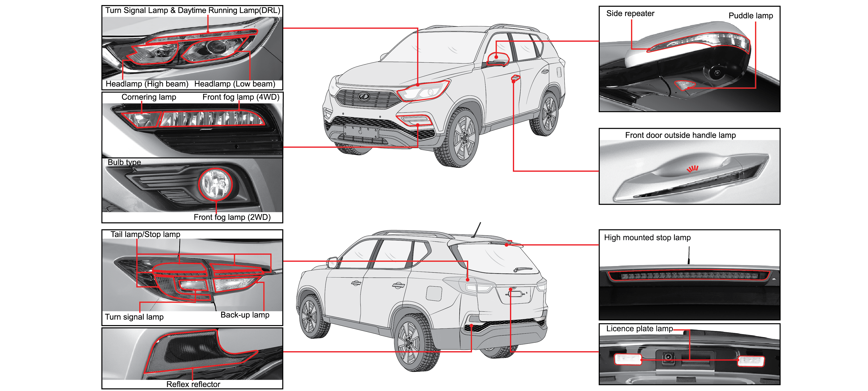 |
5.17.1 Light Switch
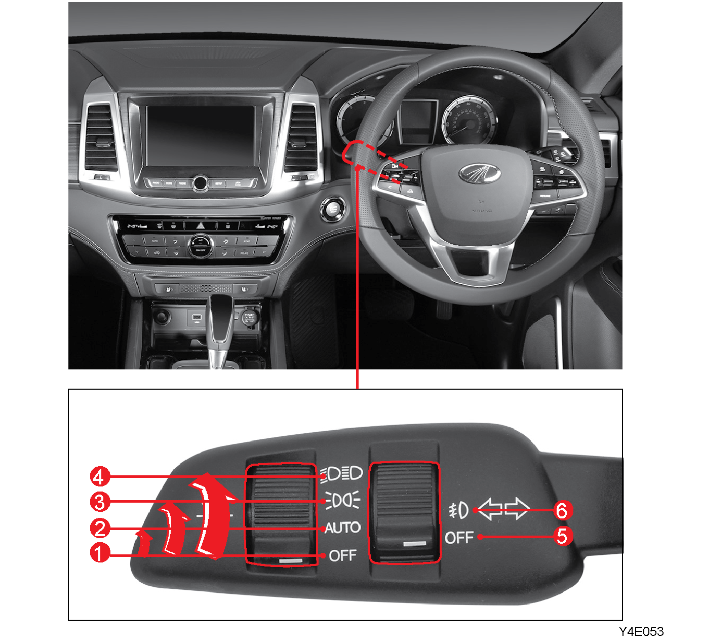
|
Light OFF (1)
|
|
Turns off the lights.
|
|
Auto light (2)
|
|
Headlamps and tail lamps are automatically turned on/off depending on the intensity of the light analysed by the automatic
light sensor.
|
|
Tail lamp ON (3)
|
|
Side-marker lights, tail lamps, licence plate lamps, front fog lamps (with front fog lamp switch ON), and other indicators
on the interior switches are turned on.
|
|
Headlamp ON (4)
|
|
Smart high beam ON
|
|
Headlamps, side marker lights, tail lamps, licence plate lamps, front fog lamps (with front fog lamp switch ON), and other
interior lights are turned on.
|
|
Front fog lamp OFF (5)
|
|
Front fog lamps are turned off.
|
|
Front fog lamp ON (6)
|
|
With headlamps or tail lamps on, front fog lamps are turned on when the switch is turned to.
|
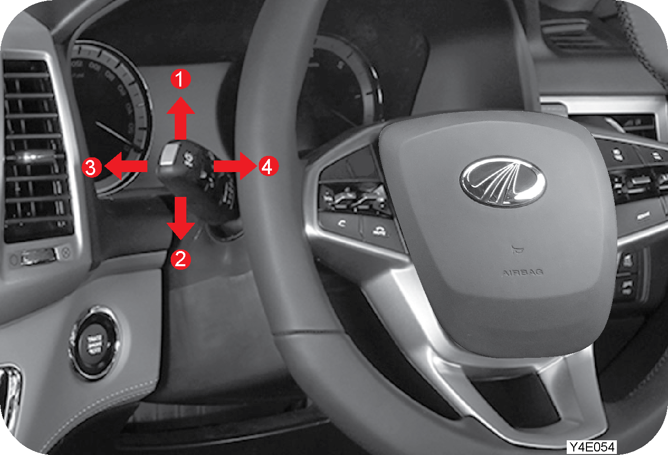
|
Right turn signal lamp blink (1)
|
|
Left turn signal lamp blink (2)
|
|
Turning up or down the light switch in the direction of the arrow makes the corresponding turn signal lamp flash.
|
|
When the turn signal lamp is flashing, the corresponding turn signal indicator on the instrument cluster also flashes.
|
|
High beam ON (3)
|
|
To turn on the headlamp high beam, push the light switch towards the instrument cluster with the low beam on.
|
|
Passing (4)
|
|
Regardless of the position of the light switch, if you pull and hold the light switch toward your body, the high beam and
low beam are turned on during the hold.
|
|
When the high beam is turned on the high beam indicator on, the instrument cluster is turned on.
|
|
Driving visibility for the drivers on the opposite side road or drivers of other vehicles may be interrupted by your headlamps.
Therefore, always check the surroundings before turning on the headlamps.
|
Your vehicle head lamps are vented and moisture may be collected on the inside of the head lamp lens under certain climatic
and geographical conditions. This moisture will evaporate once the head lamps have been switched ON for a few minutes.
5.17.2 Follow Me Home Light Control
Follow me home ON
| • | If the ignition switch is turned from ON to OFF with the headlamps (low beam) ON, the headlamps (low beam) stay on for the set time |
Follow me home OFF
| • | The headlamps (low beam) are turned off after the set time with all doors including the tailgate closed |
| • | If any door or the tailgate is open during this set time, the headlamps (low beam) will be turned off after 3 minutes |
| • | If any open door or the tailgate is closed during this set time, the headlamps (low beam) will be turned off after the set time |
| • | Turning the AUTO light and headlamp (low beam) switch to the off position turns off the light immediately |
You can set the follow me home light ON time under User settings → Light. (Disable, 10 seconds, 20 seconds, 30 seconds.)
5.17.3 Lead me to Vehicle Light
Lead me to Vehicle light ON
If the theft deterrent is disarmed by pressing the door UNLOCK switch on the smart key or door handle switch, the headlamps
(low beam) come on and stay on for the set time.
Lead me to Vehicle light OFF
| • | The headlamps (low beam) are turned off after the set time for Lead me to Vehicle light |
| • | Pressing the door LOCK switch on the smart key with Lead me to Vehicle light ON turns off the headlamps (low beam). (Theft deterrent system is armed) |
| • | Turning on the ignition switch with Lead me to Vehicle light ON turns off the light immediately |
You can set the Lead me to Vehicle light ON time under User settings → Light. (Disable, 10 seconds, 20 seconds, 30 seconds.)
5.17.4 Welcome Light

The welcome lights on the side of the vehicle (puddle lamp and door handle lamp) improve the visibility and safety at night.
The welcome lights (puddle lamp and door handle lamp) are turned on and stay on for 30 seconds,. if any of the following conditions
is fulfilled:
| • | The door LOCK/UNLOCK button on the smart key is pressed with all doors closed |
| • | The door LOCK/UNLOCK button on the door outside handle switch is pressed with the theft deterrent armed and all doors closed |
| • | You enter the area within a 1-metre radius from the vehicle while carrying the smart key |
5.17.5 Cornering Lamp
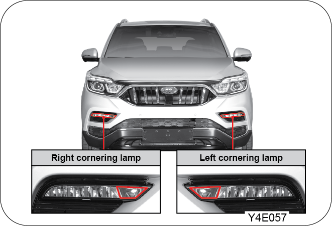
The cornering lamp automatically comes on when the vehicle makes a left or right turn to improve the visibility for the corresponding
side during night time driving.
The cornering lamp automatically comes on if any of the following conditions is fulfilled with the headlamps ON. At this time,
the fog lamps do not come on.
|
Gear selector lever |
- |
Condition 1 |
Condition 2 |
|
Position D |
Vehicle speed |
3 to 10 km/h |
10 to 40 km/h |
|
Steering wheel angle |
100° or greater |
35° or greater |
|
|
Position R |
right/Left cornering lamp AUTO ON |
||
5.17.6 Hazard Warning Flasher Switch
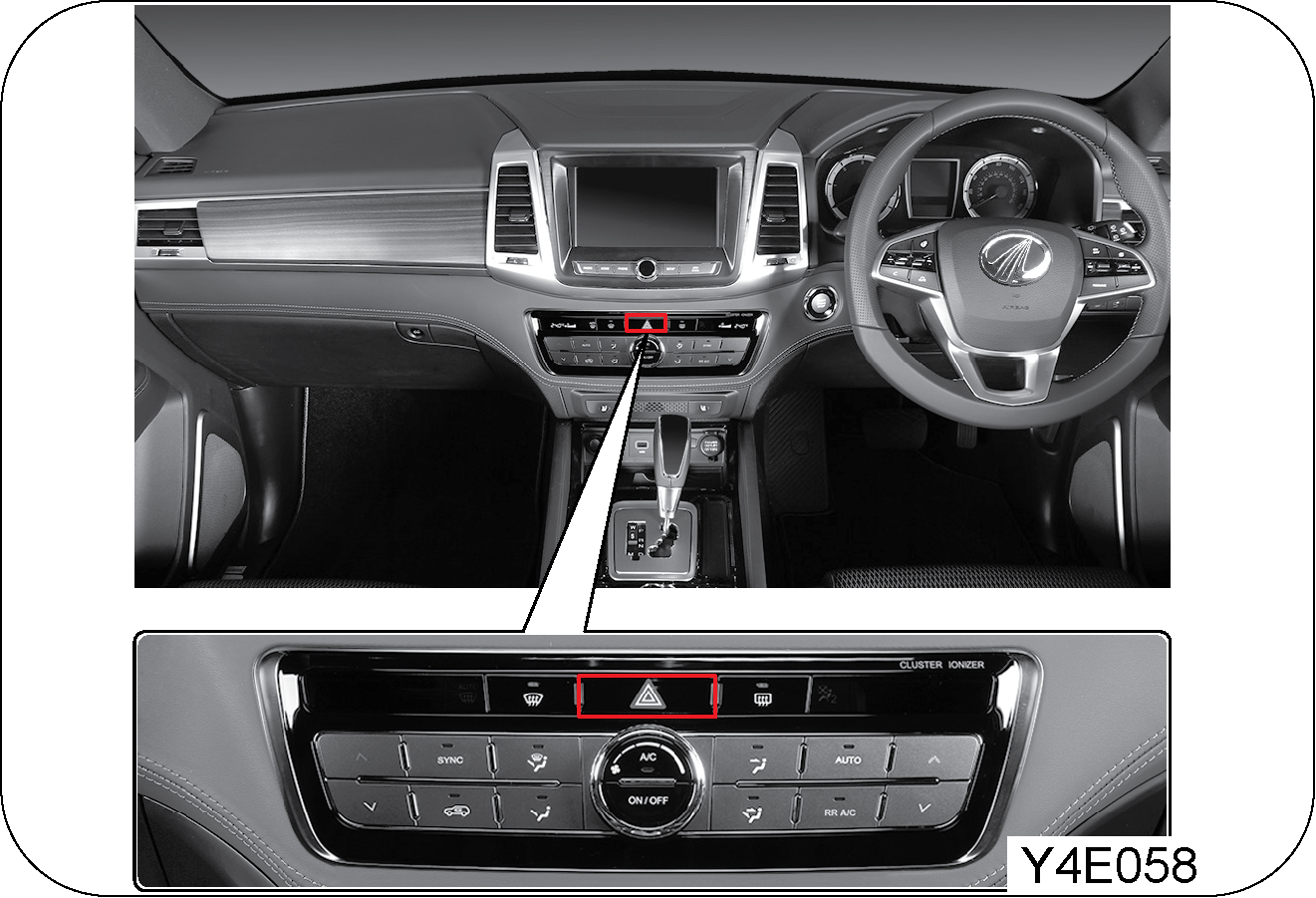
| • | To turn on the hazard warning flashers, push the hazard warning flasher switch |
| • | Use the hazard warning flasher to warn other drivers when you stop or park under emergency conditions |
Do not leave the flashers on for an extended period of time. Battery could be discharged
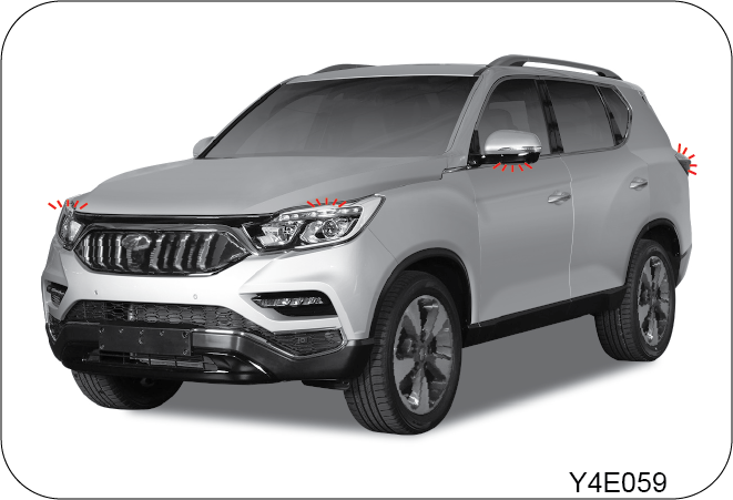
5.17.7 Daytime Running Light (if equipped)
For the vehicle equipped with DRL (Daytime Running Light), the DRL is turned on automatically when the ignition switch is
turned ON (regardless of engine running) to make your vehicle more visible to other drivers.
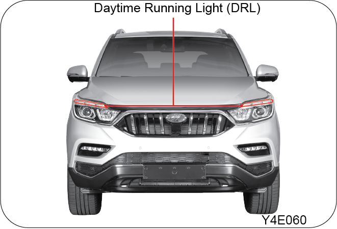
5.17.8 Daytime Running Light Operation
| • | With the key in IGN ON position (regardless of engine start), DRL will operate at all times if the fog lights/headlamps switches are OFF |
| • | Compared to the tail lamps, the DRL offers brighter light, although the DRL and the tail lamps share the same light bulb |
| • | While the DRL is operating, the tail lamps of rear combination lamp and licencee plate lamp will turn on simultaneously |
The DRL will be turned off when:
| • | Front fog lamp ON |
| • | Headlamp low beam ON or Headlamp ON by AUTO light |
| • | Parking brake (EPB) applied at the vehicle speed of 3 km/h or less (AUTO HOLD switch OFF) |
| • | Left/Right turn signal lamp activated (DRL on the corresponding side) |
| • | Hazard warning lamp flashing |
| • | IGN OFF |
5.17.9 Automatic Light (if equipped)

The auto light and auto rain sensor senses the ambient illumination intensity to determine the timing for turning the headlamps
and tail lamps on or off automatically when the light switch is set to “AUTO”.
| • | Do not clean the sensor with detergent or wax |
| • | On a foggy, snowy, rainy, or cloudy day, be sure to use manual mode. The turning on or off time of the lamps varies depending on the climate, season, or circumstances |
| • | Any aftermarket tanning film or spray may cause the lighting system to malfunction |
| • | Mahindra recommends you to use this function restrictively only at sunrise or sunset |
| • | Usually turn the head or tail lights on or off manually |
| • | Turn on the headlamps when passing through a dark area such as a tunnel |
| • | On a gloomy day, do not rely on this automatic function. But turn the head or tail lights on or off manually |
| • | When the switch is turned to the “AUTO” position, room, tail, and head lights might blink for a very short time. It is a normal phenomenon recognising the automatic setting |
5.17.10 Automatic Light & Rain Sensor (if equipped)
 |
This senses the amount of rain to operate the windshield wiper automatically (For detailed information of wiper operation,
refer to wiper and washer switch section).
Do not shake and impact the sensor. It may not work properly. On uneven road, Auto Light may work improperly due to impacts
and vibrations from the ground.
| • | In AUTO position (Light switch and Wiper switch), the head lamps are turned on when the wipers are started to operate by rain sensing |
5.18 Headlight Levelling Switch

Headlight Levelling Switch (if equipped)
With the headlights ON, the level of headlight can be adjusted by turning the switch when the vehicle heights of front and
back are different due to the number of passengers and the loading conditions of the vehicle.
4 stages (level 0 ~3) are available.
| • | To raise the level of headlight: press the button down (level 0 direction) |
| • | To lower the level of headlight: press the button up (level 3 direction) |
The higher the number on the headlight levelling switch, the smaller the headlight aiming angle
5.18.1 Headlight levelling guide
|
Level |
Level 0 |
Level 1 |
Level 2 |
Level 3 |
|
Conditions |
1 or 2 passenger(s) (Normal driving) |
7 passengers |
7 passengers and heavy goods |
1 passenger and heavy goods |
|
7- passenger seating |
 |
 |
 |
 |
| • | For safety, perform the headlight levelling before driving your vehicle |
| • | Adjust the level of headlight referring to the guide above, according to the number of passengers and the loading conditions |
Inappropriate cases of levelling
| • | Driving with level 3 under level 0 conditions (lower the level): When an emergency occurs on the road ahead, safe driving may be affected by late recognition of the emergency |
| • | Driving with level 0 under level 3 conditions (Raise the level): Driving visibility for the vehicle driving ahead or opposite side road may be interrupted by your inappropriate levelling |
5.19 Interior Lamp
 |
5.19.1 Front Roof Lamp (Overhead Console)

If the roof lamps are turned on after the ignition switch is turned off, the lamps will be turned off in approx. 10 minutes
to prevent battery discharge.
Do not turn on the roof lamps during night time driving or driving in low-light conditions. The roof lamp can cause accidents
by impairing the driver's field of vision.
1. Driver spot switch
The front roof lamp of the driver side comes on when this switch is pressed.
2. Door coupled switch
The front roof lamp and centre roof lamp come on when opening a door with this switch pressed in. If the door is closed, the
lamps fade to off.
The battery may be depleted if a door is left open for an extended period of time or you leave the vehicle with the room lamps
ON provided that the door switch is pressed in.
3. Passenger spot switch
The front roof lamp of the passenger side comes on when this switch is pressed.
4. Sunroof open/close switch
Pushing or pulling this switch opens or closes the sunroof.
Refer to Opening and Closing of Sunroof
5. Interior mood lamp brightness control switch
The brightness of the interior mood lamp can be adjusted in 5 steps by using the + and - buttons.
5.19.2 Coupled Operation With Smart Key
If the door is unlocked by a smart key with the door coupled switch pressed in, the front roof lamps are turned on and then
stay on for 30 seconds,. Pressing the LOCK button on the smart key turns off the lamps immediately.
If a door is open with the door coupled switch pressed in, the front roof lamps stay on regardless of the front roof lamp
switch operation.
5.19.3 Centre Roof Lamp

Pressing the centre roof lamp switch turns on the centre roof lamp. Pressing the switch again turns off the centre roof lamp.
The centre roof lamp comes on when the door is opened regardless of the centre roof lamp switch operation if the door coupled
switch is pressed in.
The battery may be depleted if a door is left open for an extended period of time with the door coupled switch pressed in.
5.19.4 Luggage Compartment Lamp

The luggage compartment lamp comes on when the tailgate is open and it goes out when the tailgate is closed.
The battery may be depleted if the tailgate is not closed completely or the luggage compartment lamp is left on for an extended
period of time.
5.19.5 Sun Visor Lamp (Mirror)

Swing the sun visor down and lift up the cover to reveal the mirror. The sun visor lamp is turned on when the cover is lifted
up.
You can increase the sun block coverage by using a pull out extension on the sun visor.
Always close the vanity mirror cover after use. The battery may be depleted or you could be injured in an accident if the
sun visor cover is left open.
5.19.6 Door Courtesy Lamp (Front Seat)

The door courtesy lamp is turned on when the door is opened and goes off when the door is closed.
5.19.7 Glove Box Lamp

The glove box lamp is turned on when the glove box lid is opened and goes off when the glove box lid is closed.
Driving with glove box lid open can cause injury in case of an accident or a sudden stop. Make sure that the glove box lid
is closed when driving the vehicle.
5.19.8 Foot Lamp


When the driver or passenger door is opened, the foot lamp on the corresponding side is turned on.


5.21 Rain Sensing Wiper (if equipped)
5.21.1 Wiper AUTO Position
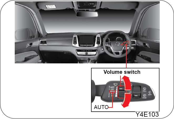
The wiping speed is adjustable by the volume switch with the wiper switch in AUTO position.
| • | It is recommended to keep the auto wipe in ON position while driving in rains and/or roads with water pools/standing water |
| • | When the wiper switch is in the “AUTO” position, the wiper will operate once if the initial engine start is made. This may wear the wiper blades prematurely (especially in winter). Therefore, other than rainy days, set the switch to the “OFF” position. In winter, ensure that the wiper blades are not frozen and are not stuck to the windshield. Otherwise, this may cause some damage to the wiper motor |
| • | If you use only the wipers when the glass is dry, this could scratch the glass and wear the wiper blades prematurely. Use the wiper with the washer when the glass is dry |
| • | Turn the wiper switch to the “OFF” position before any car wash to avoid unwanted operation of the wipers |
| • | When it is not raining, place the wiper switch at the “OFF” position |
When the wiper switch is in the “AUTO” position, this sensor detects the amount of rainfall, turns on the wiper, and controls
the intermittent wiper intervals.
5.21.2 Automatic Light & Rain Sensor (if equipped)
|
|
It controls the wiping speed by detecting the amount of rain drops.
When you clean the windshield over the sensor with damp clothes, the wiper may operate suddenly. It could cause serious injury.
Make sure to place the wiper switch and ignition switch to the “OFF” position when not in use.
| • | When the light and wiper switches are in the “AUTO” position, headlights come on if the rain sensor detects any rain. The headlights stay on for 3 minutes after the rain stops |
| • | The speed of the wipers becomes a little faster when it is dark enough to turn on the automatic lights |
| • | When the ignition key is in the “ON” position, the wiper will automatically operate once if the wiper switch is turned from the “OFF” to the “AUTO” position |
5.22 Outside Rearview Mirror Control Switch

| • | Outside Rearview Mirror Folding/Unfolding Switch (1) |
To fold outside rearview mirror, press the right side of the switch down
To unfold outside rearview mirror, press the left side of the switch down
| • | Mirror Selection Switch (2) |
Driver side mirror - R
Passenger side mirror - L
| • | Aiming Switch (3) |
Adjust the selected mirror up, down, left, or right by pressing the corresponding edges of the switch to get a desired view
5.22.1 Outside Rearview Mirror Auto Tilt Down Control In Reverse (if equipped)
If the gear selector lever is moved to the R position with the outside rearview mirror selection switch in left or right,
the outside rearview mirror will be tilted down to the set angle.
If the outside rearview mirror is tilted down automatically, it returns to its original position automatically when the position
of mirror selection switch is changed or gear selector lever is moved from the R to other position.
The options for the outside rearview mirror AUTO tilt down control in reverse (5 degrees, 4 degrees, 3 degrees, 2 degrees)
can be selected under “User settings menu > Functions for driver comfort > Outside rearview mirror angle in reverse”. The
outside rearview mirror angle for the driver and passenger sides can be set independently from each other.
Operating the mirror selection switch intensively can deactivate the mirror operation.
| • | To prevent from the mirror surface being damaged, do not scrape the ice when the mirrors are frozen |
| • | If the frozen outside rearview mirrors are not moving, do not try to move them with excessive force by hands. Otherwise, the mirrors could be damaged |
| • | The outside rearview mirrors can be folded and unfolded even after shutting off the engine |
| • | To prevent the battery from being discharged, do not operate the outside rearview mirrors with the ignition OFF |
| • | The mirror folding operation is not available when the vehicle speed exceeds 30 km/h. However, unfolding operation is available |
| • | Do not fold or unfold the outside rearview mirrors manually. It may cause a malfunction of the mirror folding system |
| • | The mirror cannot move beyond its operating range but the motor continues running as long as the switch is pressed. To prevent the motor being damaged, stop operating the switch when the mirror is at desired position |
| • | If you directly spray high-pressured water to the electric remote controlled outside mirrors, this may cause some malfunctions in the mirror system |
Do not put any tinting film on the door glasses of the front seats. Otherwise, your visibility will decrease.
Outside Rearview Mirror Auto Folding/Unfolding Mode
While outside rearview mirror Folding/Unfolding switch is in neutral position (not pressed), the outside rearview mirrors
are automatically folded when doors are locked by lock button on Smart key (theft deterrent mode activated), and the mirrors
are unfolded when doors are unlocked (theft deterrent mode deactivated). This mode is activated as follows:
Smart key:
| • | When pressing the Lock/Unlock button on the smart key |
| • | When touching the Lock/Unlock button on the outside handle of the front door |
| • | When inserting the mechanical key of the smart key into the key hole to unlock the door |
The outside rearview mirror Auto Folding/Unfolding mode will not work while the switch is pressed in any position. (left or
right)
The outside rearview mirror Auto Folding/Unfolding mode is not available when the theft deterrent system is not armed.
| • | The doors are locked with the emergency key of the Smart key |
| • | One of the doors including tailgate and engine hood is not closed completely |
| • | The ignition switch is not set to ON position (Smart key) |
Setting

| • | Activation of Auto Folding/Unfolding mode |
| • | One of the doors including tailgate and engine hood is not closed completely |
This mode is activated with the outside rearview mirror Folding/ Unfolding switch in neutral position (not pressed).
| • | Deactivation of Auto Folding/Unfolding mode |
This mode is deactivated with the outside rearview mirror Folding/Unfolding switch pressed in any position (right or left)
5.23 Manual Type Inside Rearview Mirror

Manual Day/Night Adjustment
You can manually adjust the rearview mirror by pushing or pulling its adjusting lever to avoid blindness at night due to other
vehicles behind you.
When you are not able to see the back of your vehicle at night, adjust the rearview mirror by holding the mirror body and
pushing or pulling it to a desired angle so that you can secure a clear rear view.
For your safety, adjust the mirror before driving off the vehicle.
5.24 Heater/Air Conditioner System
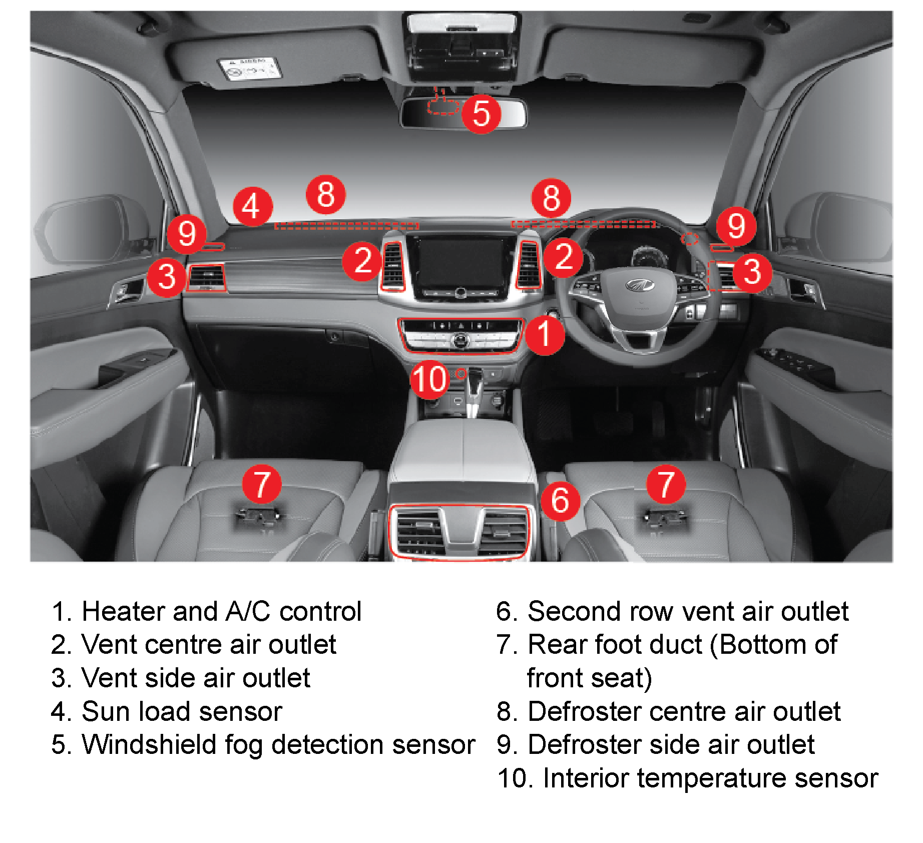

You can adjust the direction of the airflow by moving the airflow direction control lever on the air outlet.
The outlet vents can be opened or closed using the vent dial.
Do not attach items such as cup holder to the outlet guide fin. The guide fin may be damaged.
5.25 Warnings and Cautions
5.25.1 Refrigerant Specification & Capacity
|
Item |
Type B |
|
|
Specification |
R134a |
|
|
Capacity |
Dual A/C |
850 ± 30g |
| • | High pressure refrigerant is charged |
| • | Service by qualified personnel only |
| • | Refer service manual |
| • | Flammable refrigerant |
Refrigerant: R-134a
Charge: R-134a : 850 + 30g
| • | If you sleep while operating the air conditioner or heater with all the windows closed, you may suffocate to death due to lack of ventilation. When you operate the air conditioner or heater, ventilate frequently |
| • | Continued operation in the recirculation mode may cause the interior to become stuffy and windows to fog. Do not use the recirculation mode for a long period of time |
| • | If exhaust gas comes in, there is danger of carbon monoxide poisoning. Be sure to switch back to fresh air mode after passing through an area of smoke or fumes |
| • | Never leave a child or a handicapped person alone in the vehicle with the air conditioner or heater on in hot or cold weather. The child or handicapped person can be in serious danger by the heat and lack of oxygen |
| • | Refrigerant is flammable which can cause the fire by the gas leakage or static, so be very careful when handling Refrigerant |
| • | If your vehicle has been parked in direct sunlight, open all windows to extract heat before turning on the air conditioning (A/C) |
| • | Operating the air conditioning (A/C) for a long time while the vehicle is parked may cause the engine to overheat |
| • | When driving up a long hill for an extended period of time, turn on and off the air conditioner every 3 to 5 minutes |
| • | To prevent battery discharge, do not run the fan for an extended period of time when the engine is not running |
| • | To maintain the system at its optimum state and to keep the lubrication of the air conditioner compressor and related components, run the air conditioner at low speed once a week even during the season other than summer |
| • | Do not stop the engine when the air conditioner is operating. It may produce an unpleasant odour trapped in the duct. Turn the A/C off and wait for a few minutes in the fresh air mode before stopping the engine |
| • | If you start the engine with the air conditioner on, the engine may not start easily and the engine idling can be unstable causing the vehicle to vibrate. Be sure to turn off electrical systems such as the fan |
| • | When the air conditioner is not used in regularly, odour will come out. Run the air conditioner for 20 ~ 30 minutes with the windows opened and you could remove the odour |
| • | During the winter when the air conditioner is not used regularly, run the air conditioner once or twice every month for 5 ~ 10 minutes |
| • | If the air conditioner is not used regularly, the lubricant in the A/C compressor will not circulate causing the A/C to malfunction. Be sure to turn the air conditioner at low speed |
| • | When sharply accelerating the vehicle while the air conditioner is operating, you may hear a “click” sound from the magnetic clutch in compressor. This is a normal operation to protect the air conditioner system (by lowering the excessively high refrigerant pressure) |

5.27 Operation Of Heater And A/C Control
5.27.1 Heater And A/C ON/OFF
| • | Pressing ON/OFF switch (1) turns ON the climate control system. The system is turned on with previous status resumed |
| • | Pressing the ON/OFF switch again (1) turns off the system |

5.27.2 Driver/Passenger Side Temperature Control Switch
Press the driver side temperature control switch (1) to set the temperature on the driver side:
| • | Operating this switch with the SYNC indicator (3) ON changes the passenger side temperature simultaneously |
| • | The set temperature can be changed in 0.5°C graduations with this switch |

5.27.3 Independent Temperature Control
| • | Press the SYNC switch (4) or driver side temperature control switch (2) |
| • | The SYNC indicator (3) is turned off |
| • | Under this condition, the temperature setting for the driver and front passenger sides are controlled independently |
5.27.4 SYNC With Driver Side Temperature
| • | Press the SYNC switch (4) |
| • | The SYNC indicator (3) is turned off |
| • | The temperature setting for both the driver and front passenger sides is controlled by the driver side temperature control |
| • | If temperature is set to LO: |
The system is automatically set to A/C ON, vent mode, recirculation mode.
| • | If temperature is set to HI: |
The system is automatically set to A/C OFF, foot mode, fresh air mode.
AUTO Control
Use this feature while the engine is running:
| • | If the AUTO switch (1) is pressed, the indicator on the switch is turned on |
| • | Set the temperature as desired using the temperature control switch (2) |
| • | The fan speed and air distribution mode are controlled automatically based on the set temperature, indoor temperature, and outdoor temperature |
| • | Pressing recirculation/fresh air switch, fan speed dial, air distribution mode switch, A/C switch, or defroster switch in AUTO mode deactivates the AUTO mode and the system is set to manual mode (The indicator on the AUTO switch goes off) |

Manual Control
Use this feature while the engine is running:
| 1. | Press the ON/OFF switch (1) |
| 2. | Set the temperature as desired using the temperature control switch (2) |
| 3. | Turn the fan speed dial (3) to adjust the amount of air flow |
| 4. | Press the air distribution mode switch to select the direction of the air flow |
| 5. | Press the recirculation/fresh air switch (4) to select the air source |
| 6. | Press the air conditioner switch (5) to use A/C |
Pressing the AUTO switch in manual mode changes the climate control system to AUTO mode and the climate functions are controlled
automatically based on the set temperature.

 |

5.27.6 Glass Heater Switch
| • | Pressing this switch turns on the heating element of the glass for 12 minutes (indicator ON) |
| • | Press the switch again to stop the operation (indicator OFF). Use this switch to dehumidify the indoor air or defrost |
| • | If the switch is pressed again within 10 minutes after completion of its first operation cycle (12 min.) the heating element of the glass will be turned on for about 6 minutes |
| • | The indicator on the switch comes on when the heating element is in use |

The heating element of the glass is activated only when the engine is running. When the glass heater switch is pressed, the
heating elements of the rear window, windshield, and outside rearview mirrors are turned on simultaneously.
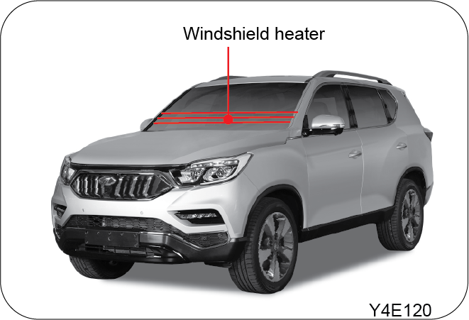 |
 |
5.27.7 How to Dehumidify Window Glass
| • | Press the defroster switch (1) (indicator ON) |
| • | Rotate the fan speed dial (2) from the OFF position |
| • | To quickly remove the fog on the glass, set the fan speed dial (2) to a high speed position |
| • | To remove the fog on the outside of the glass, set the temperature high |

To prevent the windshield from fogging up, it is recommended to set the recirculation/fresh air switch (3) to the fresh air
mode. Pressing the defroster switch (1) turns on the A/C, sets the system to fresh air mode, and selects a fan speed (at least
1st fan speed). Pressing this switch again returns the system to its original condition
| • | Excessive use of A/C with air distribution in foot mode, defroster/foot mode, or defroster mode creates a higher difference between indoor and outdoor temperature. This temperature difference causes the fogging on the outside of the windshield. If this is the case, use the wiper blades to immediately clear fog on the windshield and change the air distribution mode to vent mode (toward face) to minimise the temperature difference |
| • | Make sure to remove any foreign materials such as snow and leaves on the air inlets to avoid window fogging, especially in winter and summer |
With rainy or highly humid condition, fog appears on the windshield or front side windows even the A/C is ON. If windows are
foggy, it is dangerous to drive because of poor frontal and side visibilities. If this is the case, press the recirculation/fresh
air switch to select fresh air source and select the defroster mode for air distribution to direct the air to the windshield
5.27.8 AQS (Air Quality System)
The AQS (Air Quality System) blocks the fresh air inlet to prevent the harmful gases from entering if the concentration of
hazardous gases in air is higher than the specified value.
If the concentrations of hazardous gases go below the specified values, the system is automatically switched to the fresh
air mode.
AQS indicator
At initial engine start-up, the AQS indicator comes on (1) and the recirculation air indicator comes on (2) for 40 seconds.
During this time, AQS is warmed-up and its function does not work.
If hazardous gases are detected in the outside air in AUTO mode, the system is switched to recirculation mode. At this time,
the AQS indicator (1) and indicator on the recirculation/fresh air switch (2) are turned on.
The AQS blocks the intrusion of hazardous gases, such as NO, NO2, SO2, CO, with concentration higher than the reference value.
It cannot protect the vehicle from odour..

Deactivation conditions
| • | Air source is selected manually by pressing the recirculation/ fresh air switch |
| • | The driver side set temperature is set to ‘LO (lowest)’, ‘HI (highest)’ |
| • | AUTO defogger is activated (AUTO defogger overrides AQS) |
| • | The defroster and defroster/foot mode switch is pressed |
| • | The ON/OFF button is pressed to turn off the climate control system |
Enabling/disabling AQS
How to set
Press and hold the recirculation/fresh air switch (3) and briefly press the OFF switch (4) 5 times within 3 seconds,. (AUTO
indicator (5) + recirculation/fresh air indicator (2) flash for 3 seconds,.)
How to disable
Press and hold the recirculation/fresh air switch (3) and briefly press the OFF switch (4) 5 times within 3 seconds,. (AUTO
indicator (5) flashes for 3 seconds,.)
| • | If driving in urban area or polluted area for a long time is necessary, there is a risk for moisture accumulation in the cabin due to prolonged operation of AQS. Because of this accumulated moisture, the AUTO defogger may be activated resulting in AQS deactivation |
| • | The AQS activation may be delayed or it may not operate at all depending on the driving conditions |
5.27.9 Auto Defogger System
If the inner side of windshield fogs up during heater or A/C operation, the AUTO defogger system removes the moisture on the
glass to guarantee optimum visibility for safety reasons.
If moisture on the glass is detected, the AUTO defogger indicator (1) comes on indicating that the moisture on the glass is
being removed automatically.
The higher the humidity, the higher the AUTO defogger operation level. For example, if operation level 1 does not help operation
level is switched from level 2 to level 4 in sequence until the humidity is controlled properly
Level 1 - Air source selection is changed to fresh air mode
Level 2 - A/C ON
Level 3 - Defrost mode(Air is directed to windshield)
Level 4 - Fan speed increases (Deforest mode)
Enabling/disabling AUTO defogger
How to disable
Press and hold the defroster switch (2) and briefly press the ON/OFF switch (3) 5 times within 3 seconds,. (Indicator on defroster
switch flashes for 3 seconds,.)
How to set
Press and hold the defroster switch (2) and briefly press the ON/ OFF switch (3) 5 times within 3 seconds,. (AUTO defogger
indicator (1) flashes for 3 seconds,.)

| • | Pressing the recirculation/fresh air switch to activate recirculation mode during AUTO defogger operation reduces defogging effect. To maximise the visibility, do not press the recirculation/fresh air switch during AUTO defogger operation |
| • | Never remove the sensor cover on the upper side of the windshield. The AUTO fog detection sensor can be damaged while removing the cover |
5.28 Rear Air Conditioner (Dual A/C)
5.28.1 Operation Of Rear Air Conditioner

| • | Press the rear air conditioner switch |
| • | Turn the rear air flow control dial (A) to any position (1 ~ 3) from “0” position |
| • | Adjust the air flow direction with the flow direction control lever (B) |
| • | If the rear air conditioner switch in front control panel is turned off, the rear air conditioner does not work even when the rear air flow control dial is operated. However, the air flows due to fan operation |
| • | The rear air conditioner is only for air cooling. It does not include the air heating function |

5.29 Defogging and Defrosting
Inside of the Windshield
| • | Press the defroster switch |
| • | Adjust the fan speed with the fan speed control |
| • | To quickly remove the moisture on the glass, set the fan speed button at a high speed position |
| • | To prevent fog from forming on the glass, setting the air source selection switch to the fresh air intake mode is recommended |
Outside of the Windshield
| • | Press the defroster switch |
| • | Adjust the fan speed with the fan speed control |
| • | To quickly remove the frost on the glass, set the fan speed button at a high speed position |
| • | Set the temperature control switch to a hot position |
When it rains and is very humid, you may have fog on the windshield and windows. The fog will block your view through all
windows and can create a dangerous situation. To prevent any fog on the glass, setting the air source selection switch to
the fresh air intake mode is recommended
When you press this defrost switch, the air conditioner turns on automatically and the system selects the fresh air intake
mode
Automatic Heater & Air Conditioner

| • | An extended air conditioner operation in the bi-level mode or defrost mode may cause the outside glass to fog due to the high temperature difference between the inside and the outside of the vehicle. In this case, change the air flow to the fresh air intake mode and set the fan at a low speed |
| • | Especially in winter or summer, to avoid glass fogging, remove any obstacles such as snow or leaves on the air inlets. |
5.30 Multimedia

MODE
| • | Pressing the mode button briefly with the audio system off turns the system on |
| • | Audio mode changes every time the MODE switch is pressed |
˄ SEEK / ˅SEEK
On media screen
| • | SEEK switch tapping up/down: Goes to previous/next song |
| • | SEEK switch pushing up/down and holding: Plays current track and shows list of previous/next songs |
Using media player other than media screen
| • | SEEK switch tapping up/down: Goes to next /previous song |
| • | SEEK switch pushing up/down and holding: Plays current track and shows list of next/previous songs |
In radio screen
| • | SEEK switch tapping up/down: Goes to previous/next stored station |
| • | SEEK switch pushing up/down: Searches for next/previous station |
Using other radio player other than media screen
| • | SEEK switch tapping up/down: Goes to previous/next stored station |
| • | SEEK switch pushing up/down: Searches for next/previous station |
BLUETOOTH HANDSFREE
Call switch used for Bluetooth handsfree call with a mobile phone.
For more detailed information on audio and Bluetooth handsfree system, refer to Audio Operating Manual provided separately
MUTE
| • | When the switch is pressed and held, the audio system (AV) will be turned off |
| • | Pressing the switch briefly with the audio system on turns off all sound outputs. To resume the audio output, press the switch again |
This owner's manual describes information on features that are common between all audio models. For detailed information regarding
the audio system installed to your vehicle, refer to the operating manual provided separately
5.30.1 Smart Audio
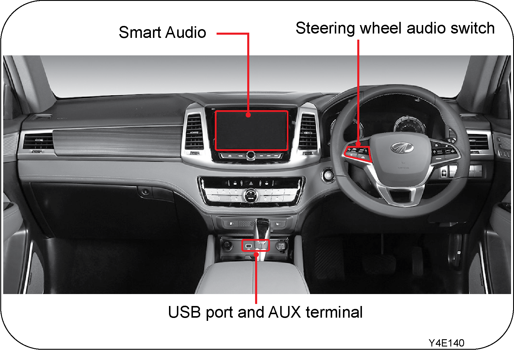
The Smart audio system has a 8-inch touch panel and steering wheel audio switch cluster. You can connect an external device
to this system using the USB (for i-Pod) and AUX terminal. The system also supports SD card (for playing music)/rear view
camera/around view camera/WIFI mirroring (for Android), and Bluetooth.
AV play through AUX terminal is not supported.
Current mode and media information (title, playing time) displayed on the smart audio display can be displayed on instrument
cluster.
| • | For safety reasons, only the voice is played without video during driving. (video played again when vehicle stops) |
| • | SD Card slot supports only the sound data and the SD Card may not be provided. |


5.31 Steering Wheel
5.31.1 Steering Wheel Tilting/Telescoping

Push down the steering wheel lock / release lever (1) to tilt (2) or telescope (3) the steering wheel. Adjust the steering
wheel to the desired position and lock it by pulling up the lever.
Hold and move the steering wheel to check if it is locked in place.
Avoid turning the steering wheel all the way to the left or right for more than 10 seconds with the engine running. This may
cause the power steering system to be overloaded, causing damage to the system.
Do not adjust the steering wheel while your vehicle is moving. Always adjust the steering wheel with the vehicle stationary
Before driving, make sure that the steering wheel is locked

5.32 Storage Compartments
5.32.1 Glove Box

The glove box opens with the button pushed pulled. Use it to store items and etc.
The glove box lamp comes on when opening the glove box with the tail lamp ON.
| • | Driving with the glove box lid open can cause injury in case of an accident or a sudden stop. Keep glove box lid closed when driving |
| • | Do not store any flammable materials such as cigarette lighter in the glove box or other space. In hot weather, it may explode and cause a fire |
5.32.2 Front Storage

The front storage is located under the front Centre panel. You can use it for small items.
Be cautious of items falling or interrupting the control of the gear selector lever.
5.32.3 Sunglass Holder

Press the Centre of the cover to open the cover and push it up to close.
If the holder cover is left open during driving, it can block the rearview mirror. Also, it can cause personal injury in an
accident or sudden stop. Always close the cover after use
5.32.4 Console Storage Bin

Swing the console storage bin cover up by pressing the lock knob
| • | To avoid possible theft, do not leave valuables in the storage compartment |
| • | Do not store items that are damageable or cause noises since they can move around in the compartment while driving |
| • | Do not store any flammable materials such as cigarette lighter in the console box or other space. In hot weather, they may explode and cause a fire |
5.32.5 Door Map Pocket

Various items including maps, books, or magazines can be put in here.
Bottles for water or beverages can be stored in the bottle tray.
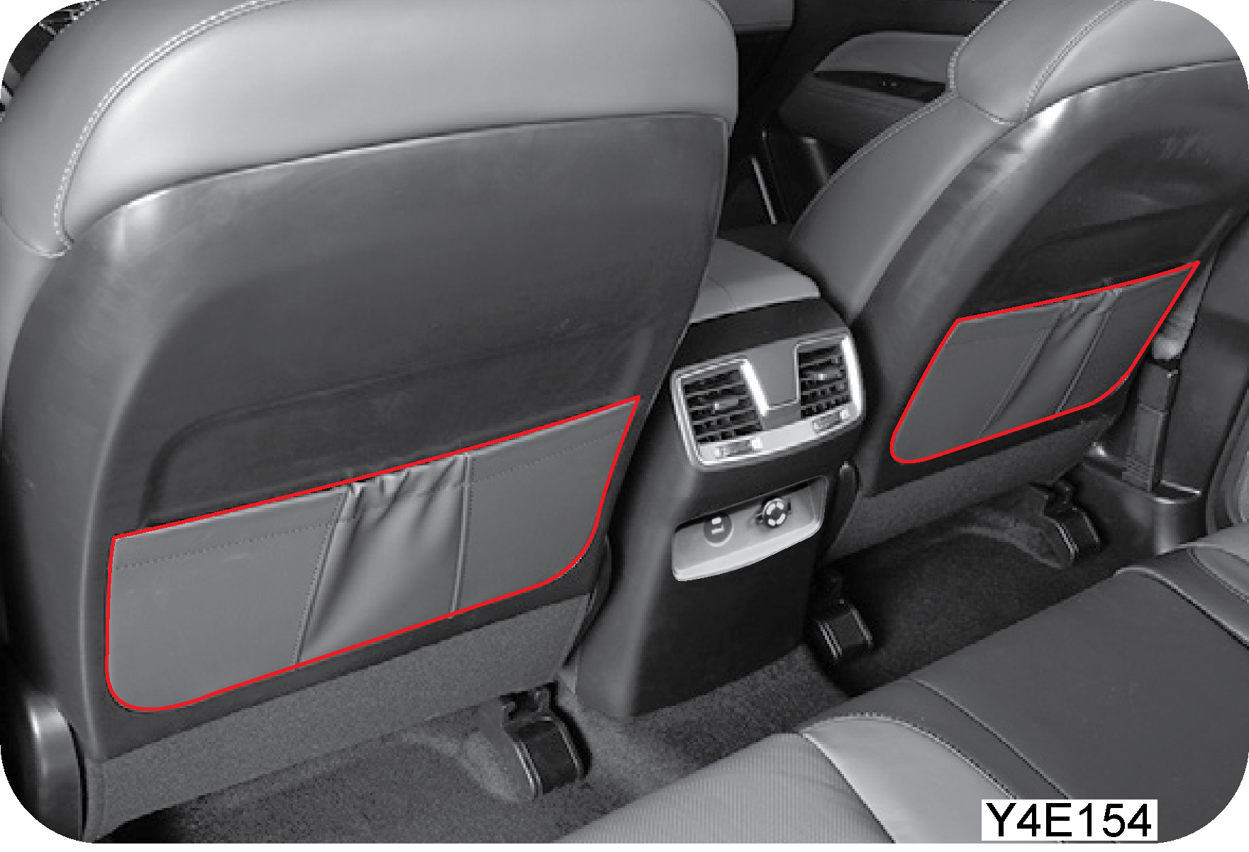

5.33 Sun Visor
5.33.1 Sun Visor and Ticket Holder (Driver Side)
Sun Visor

Swing the sun visor down (1) to block out the sun (front, left side).
Rotate the sun visor to the driver seat side to block out the sun from the left side. Pull out extension on the sun visor
for increased coverage (lengthwise) (2).
Ticket Holder

Tickets and cards can be stored.
| • | Adjusting the sun visor or using the mirror or ticket holder on the sun visor while driving may cause an accident by taking your attention away or blocking your view |
| • | Adjust and use the sun visor when the vehicle is not on the move. |

5.34 Front Cup Holder/Rear Cup Holder And Armrest


5.35 Power Outlet
5.35.1 Front

An auxiliary power outlet for extra electrical devices is installed. This power outlet supplies power when the ignition key
is in the “ACC” or “ON” position.
Keep the power outlet cover closed if not in use. Electrical defects can occur if objects other than power outlet plugs or
water gets in. This will prevent the socket from becoming clogged or short circuiting.
5.35.2 Rear

| • | For the extra electrical devices, you must use this power outlet. If you alter the vehicle’s wire lines and leave the wires to hang freely, it could cause an accident like a fire |
| • | Abide by the nominal capacity of 12V-120W |
| • | Do not put a finger into the outlet. It may cause an electric shock |
| • | The battery can be discharged if the power outlet is used excessively when the engine is not running |
5.36 USB


You can charge your smartphones or tablet devices by using this port.
| • | Connect a USB cable connected to your device to the USB charge port with the engine running |
| • | USB charger located read side of centre console has indicator but it lights when ACC is ON |
| • | USB charger located centre fascia has no indicator |
| • | For charging progress, check the display of your device |
| • | Using this port to charge your device with the ignition turned OFF may run down the vehicle battery faster |
| • | Prevent the foreign body or moisture from entering the USB charger socket. Otherwise, the USB charger can be damaged |
| • | Do not connect a device with current consumption of higher than 2.1 A to this port. |
| • | Starting the engine or abrupt voltage change with a device connected to the socket can lead to product damage. Therefore, connect a device only after the ignition is turned ON and disconnect the device before IGN OFF |
| • | Improper connection of a charging cable with the USB charger can damage the vehicle fuse or the connected device because of short circuit. |
| • | The charging speed varies depending on the device type, compatibility, charging cable and other vehicle conditions |
5.37 Grip Handle With Coat Hanger
5.37.1 Grip Handle With Coat Hanger (Headlining)

There are grip handles on top of the driver side and rear seat. The grip handle for the rear seat has a coat hanger.
Do not hang heavy cloth. It can damage the coat hanger and headlining.
There are grip handle in the front side of rear seat side to grab for easy entry.

5.38 Roof Rack

If the vehicle has a roof rack, you can load things on top of your vehicle.
When loading, stowage on the vehicle should not damage the vehicle as well as not interfere with the sunroof operation (for
sunroof equipped vehicle).
Use any auxiliary equipment for loading, such as a carrier, considering the vehicle condition and safety.
It is recommended to put cloth or cushions between stowage and roof to protect them.
| • | In case the sunroof is equipped, do not position roof rack loads that could interfere with opening of the sunroof |
| • | The following specification is maximum weight when loading cargo or luggage |
| • | Roof rack: 100 kg (220 lbs.) evenly distributed |
| • | Loading cargo or luggage above specification on the roof rack may damage your vehicle |
| • | When you carry large objects, never let them hang over the rear or the sides of your vehicle |
| • | To prevent damage or loss of cargo as you are driving, check frequently to make sure the luggage carrier and cargo are still securely fastened |
| • | Always drive your vehicle at a moderate speed |
| • | Loading cargo or luggage over specification on the roof rack may damage stability of your vehicle |
When loading the cargo on the roof rack over the vehicle equipped with the sun roof, be careful not to interrupt the sun roof
operation.
6 CONVENIENCE SYSTEM II
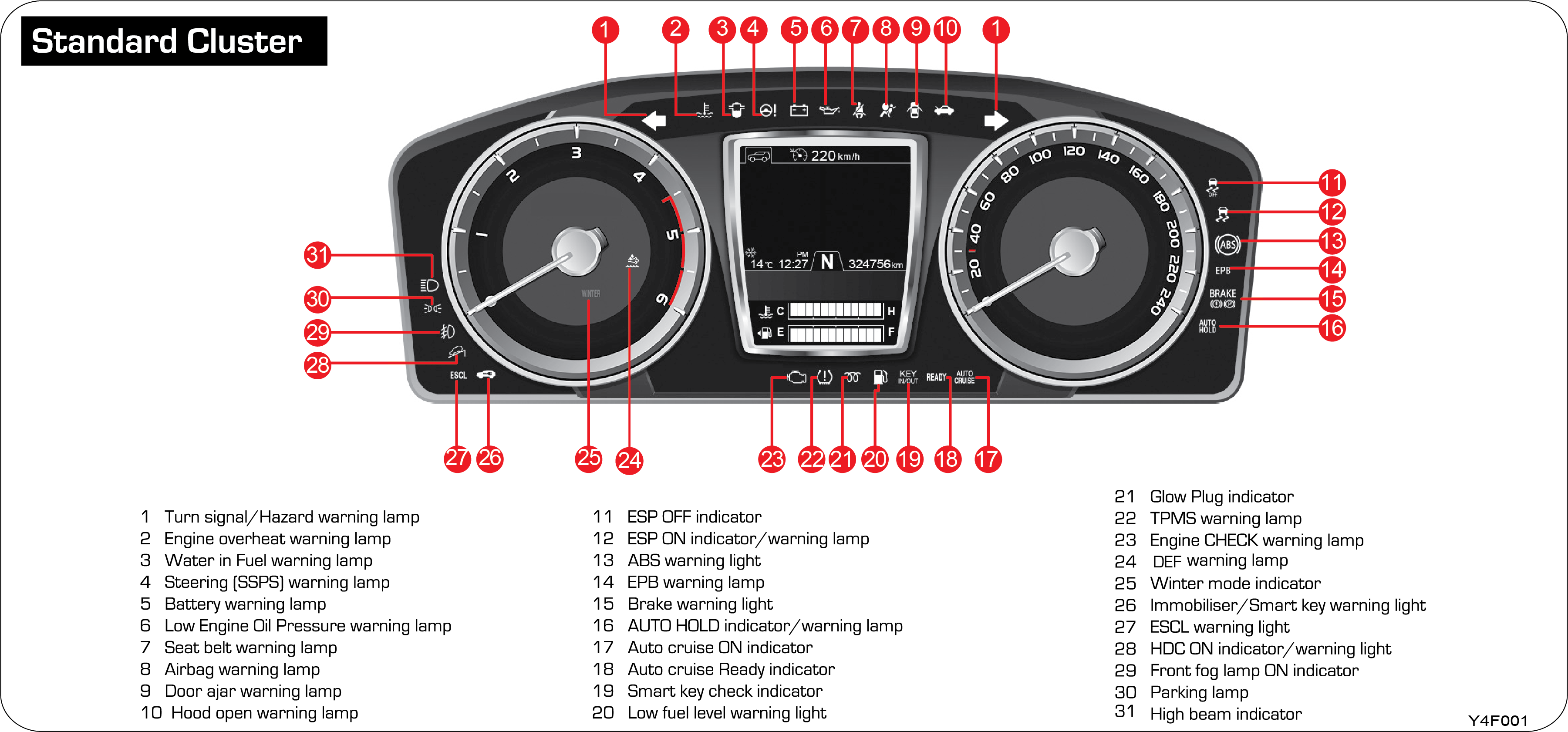

6.2 Gauges and Display Window
6.2.1 Tachometer
|
Supervision cluster |
Standard cluster |
 |
 |
The tachometer indicates engine speed in revolutions per minute. Multiply 1000 to the current number, then it will be the
current number of engine revolutions.
Do not operate the engine within the red zone. This may cause severe engine damage.
6.2.2 Speedometer
|
Supervision cluster |
Standard cluster |
 |
 |
The speedometer indicates the vehicle speed in kilometres per hour (km/h) .
 |
6.2.3 Over Speed Alert
| • | Primary level: Buzzer will trigger single chime in every 120 seconds when the vehicle speed reaches above 80 kmph to 119 kmph. |
| • | Secondary level: Buzzer will trigger continuous / intermittent single chime in every 2 seconds. When the vehicle speed reaches above 120 kmph. |
6.2.4 Coolant Temperature Gauge
 |
 |
The temperature gauge indicates the temperature of the engine coolant. If the gauge moves beyond the normal operating range
toward “H” mark. it indicates the engine overheating that may damage the engine. Allow engine to cool.
If the engine is overheated, continued operation of the vehicle may seriously damage the engine.
6.2.5 Fuel Gauge
 |
 |
| • | This gauge indicates the level of fuel remaining in the fuel tank. Fill up the fuel tank before the gauge pointer reaches “E”. The gauge may slightly move during braking, turning, accelerating, or going up or down hills |
| • | This symbol indicates that the fuel filler is located on the left side of vehicle |
Always stop the engine before refuelling
| • | Use only the designated fuel. Otherwise, engine could be seriously damaged |
| • | If you use inappropriate grade fuel or put improper fuel additives into the fuel tank, the engine may seriously be damaged |
| • | Do not drive your vehicle when the fuel level is low. Otherwise, the catalytic converter could be damaged due to incomplete combustion |
6.2.6 Odometer
 |
 |
The total distance the vehicle has been driven is displayed in kilometres. Maximum number of kilometres is 999999 km. Odometer
is always shown on the bottom in the display.
6.2.7 Shift Lever Indicator
 |
 |
| • | The current position of shift lever is displayed |
| • | For the manual mode of auto transmission vehicles, the optimal shift point is indicated by an arrow according to vehicle speed and RPM condition |
6.2.8 Gear Shift Indicator
|
|
|
Automatic Transmission
This indicator shows the current position of the gear. In normal mode: P, R, N, D Gear indication in “M” mode: 1, 2, 3, 4,
5, 6, 7
|
P |
Parking |
1 |
1st gear |
|
R |
Reverse |
2 |
2nd gear |
|
N |
Neutral |
3 |
3rd gear |
|
D |
Driving (7A/T) (1~7th gear shifting) |
4 |
4th gear |
|
5 |
5th gear |
||
|
6 |
6th gear |
||
|
7 |
7th gear |
While driving in 1st~7th gear position without shifting gear in automatic transmission (M mode) vehicle, the transmission
may automatically shift up to protect the system if the engine RPM gets high.
While driving in 2nd~7th gear position in automatic transmission (M mode) vehicle, the indicator q (arrow) does not appear on display when downshifting. Drive shifting manually according to driving conditions. If driving
without manual shift, RPM will get low and the system will shift down.
Automatic transmission display
| • | 7A/T |
6.3 Warning Lights and Indicators
6.3.1 Seat Belt Warning Lamp
This warning light blinks and the warning buzzer sounds for 6 seconds when the ignition switch is turned to the “ON” position
unless the driver & passenger seat belt is securely fastened. This reminding operation stops when the driver fastens the seat
belt even during its operation period. When the vehicle speed exceeds 10 km/h (general: 10 km/h) without fastened driver’s
seat belt, this indicator comes on and the alarm sounds.
6.3.2 Airbag Warning Lamp
When the ignition is switched on, this warning light illuminates and then should go off, to confirm that the airbag is operational.
If it does not come on, or if it does not go off, or if it flashes or illuminates continuously while driving, it means that
there is a malfunction in the system. Have the airbag system checked without delay by a Mahindra Dealer or Mahindra Authorised
Service Centre.
For more detailed information, refer to the “Seat Belt and Air Bag” section.
6.3.3 Engine Oil Pressure Warning Lamp
This warning light comes on when the oil pressure drops because the low engine oil level. If this light turns on while driving,
safely pull over and stop the vehicle to check the engine oil level. Add engine oil, if necessary, to maintain the proper
oil level. Continuous driving with this light on may lead to engine failure.
If this light does not go off after engine starting or comes on while driving, it means there is a malfunction in the system.
Running the engine with this warning light on can cause serious damage to the engine. Have the lubricating system checked
by a Mahindra Dealer or Mahindra Authorised Service Centre.
6.3.4 Battery Charge Warning Lamp
This warning light comes on when the ignition switch is turned on and it goes off when the engine is started. If this light
doesn’t go off after engine starting or comes on while driving, it means there is a malfunction in the system. Have the charging
system checked by a Mahindra Dealer or Mahindra Authorised Service Centre.
Continued driving with the battery charge warning light illuminated will lead to a sudden stop of vehicle, causing an accident
and serious injury.
6.3.5 Door Ajar Warning Lamp
This light comes on when a door or the tailgate is either opened or not closed securely.
Before driving, check that the door ajar warning light is off. When a door is not completely closed, it may accidentally open
while driving.
6.3.6 Hood Open Warning Light
This light comes on when the engine hood is open or not closed completely.
Driving with engine hood open can result in hazards when driving. Make sure the engine hood is closed securely before driving
off.
6.3.7 DEF Warning Light

This light comes on when the ignition switch is ON position and goes off when the engine is started.
This warning lamp is lit when the level of DEF solution is low or the DEF system (unit) is faulty.
If you are operating the vehicle continuously with the warning lamp lit, it may cause serious damage to the DEF solution system
or make it impossible to operate the vehicle. In such cases, be sure to replenish the DEF solution immediately or have it
inspected and serviced by Mahindra Dealer or Mahindra Authorised Service Centre.
6.3.8 Engine Temperature Warning Lamp
When the engine coolant temperature is abnormally hot, the engine overheat warning light blinks and a warning buzzer sounds.
When this happens, stop the vehicle in a safe place and let the engine cool down. For more information, refer to Chapter 6
“When the engine is overheating”.
If you keep driving the vehicle with the warning light and buzzer on, the engine could be damaged and lead to a fire. After
completely cooling down, have the system checked by Mahindra Dealer or Mahindra Authorised Service Centre.
6.3.9 Steering (SSPS) Warning Lamp
This warning light comes on when the Steering (SSPS) system is defective. When this warning light comes on, the steerability
becomes heavier.
What is SSPS?
Speed Sensing Power Steering (SSPS) is the device that provides good driving condition and steering stability by making the
steerability heavier in high-speed driving, and lighter in stop or low-speed driving.
If the SSPS warning light comes on or when you feel the steering wheel heavy, have the SSPS system checked by Mahindra Dealer
or Mahindra Authorised Service Operation.
6.3.10 Water in Fuel Warning Lamp
This warning light comes on when the ignition switch is turned to “ON” and should go off in a few seconds. When the water
inside the water separator in the fuel filter exceeds a certain level, this warning light comes on and a buzzer sounds. Also,
the driving force of the vehicle decreases. If this warning light comes on while driving, have the system checked by Mahindra
Dealer or Mahindra Authorised Service Centre.
| • | The fuel system in the engine may get serious damage if you keep driving while the warning light is on. Prompt correction should be necessary |
| • | Using low quality fuel could result in serious damage to the engine due to the water or impurities in fuel. Never use low quality fuel |
| • | If the amount of water in the fuel filter exceeds the specified level, the warning lamp comes on, a chime sounds or the engine power decreases |
6.3.11 Parking Brake ON/Brake Fluid Low
This warning light comes on when the parking brake is applied and/or the brake fluid level is lower than a specified level.
Driving the vehicle with the brake fluid warning light on is dangerous. If the parking brake light stays on, you must immediately
have your vehicle checked and serviced by Mahindra Dealer or Mahindra Authorised Service Centre.
6.3.12 ABS Warning Lamp
This warning light comes on when the ignition switch is turned to “ON” and should go off in a few seconds.
| • | If this light stays on after starting the engine or comes on while driving, have the system checked by Mahindra Dealer or Mahindra Authorised Service Centre. In this case, the ABS function is not available, but the conventional brake system is properly working |
| • | ABS is a device that prevents wheels from locking during braking to allow steering. However, the ABS system does not shorten the stopping distance |
ABS system performs self diagnosis by transferring hydraulic pressure to the brake units for few seconds after starting the
engine. This may cause some noise and vibrations. This means ABS is properly functioning.
6.3.13 EBD Warning Lamp
If the ABS warning light and the brake warning light come on simultaneously, EBD (Electronic Brake force Distribution) system
is defective. In this case, ABS system also cannot be activated.
If this happens, have the system checked by Mahindra Dealer or Mahindra Authorised Service Centre.
When the EBD system is not functioning, the vehicle could be unstable during hard braking. Therefore, you must pay particular
attention to the driving conditions while this warning light is on.
6.3.14 EPB Warning Lamp
The lamp comes on when the ignition switch is turned ON and then goes off after about 4 seconds.
ON: The EPB (Electric Parking Brake) system is faulty but the parking brake works properly
Flashing: The parking brake is not working with this lamp ON
| • | If the warning lamp is turned on, have the vehicle checked and serviced at a Mahindra Dealer or Mahindra Authorised Service Centre |
| • | If you have to park the vehicle with faulty EPB, safely pull over and stop the vehicle on a flat surface and shift the gear selector lever to the P position |
6.3.15 Auto Hold Indicator / Warning Lamp (if equipped)
When the AUTO HOLD switch is operated, the AUTO HOLD system will be switched to READY mode and the "AUTO HOLD" indicator on
the instrument cluster will be illuminated in white.
Operating the AUTO HOLD switch again turns off the indicator and deactivates the AUTO HOLD system.
| • | Indicator ON in white: AUTO HOLD system READY mode |
| • | Indicator ON in green: AUTO HOLD system is activated |
| • | Warning lamp ON in yellow: fault in AUTO HOLD system |
If the yellow AUTO HOLD warning lamp is turned on, have the vehicle checked and serviced at a Mahindra Dealer or Mahindra
Authorised Service Centre.
6.3.16 OBD Check Lamp
This warning light comes on when the ignition switch is turned on and it goes off when the engine is started.
If the light stays on or comes on while driving, some of the engine control components including sensors and devices are defective.
If the engine halts due to a completely empty fuel tank and the engine check light comes on even after refuelling, the engine’s
power output may decrease within a certain driving distance (about 30 km).
When this warning light comes on, the vehicle operates in safety mode to maintain minimum driving conditions and to prevent
the system from being damaged. In this mode, the engine driving force may be decreased or the engine may stall. When this
happens, have the system checked at the nearest Mahindra Dealer or Mahindra Authorised Service Centre.
6.3.17 4WD Check Warning Lamp (if equipped)
This warning light comes on when the ignition switch is turned to “ON” and should go out if the system is normal. If the “4WD
CHECK” warning light stays on, have the 4WD system checked by a Mahindra Dealer or Mahindra Authorised Service Centre.
| • | If the “4WD CHECK” warning light stays on, have the 4WD system checked |
| • | Do not drive your vehicle over 80 km/h in 4H mode |
6.3.18 4WD Low Indicator (if equipped)
When shifting the driving mode to “4L”, this indicator blinks until the shifting operation is completed. After completion
of the mode change to 4L, the indicator comes on.
6.3.19 4WD High Indicator (if equipped)
When shifting the driving mode from “4L” to “4H”, this indicator blinks until the shifting operation is completed. After completion
of the mode change to 4H, the indicator comes on.
6.3.20 ESP ON Indicator/ Warning Lamp (if equipped)
The lamp comes on when the ignition switch is turned ON and then goes off after about 4 seconds.
Indicator flashing: ESP system is activated
Warning lamp ON: Fault in ESP system
If the warning lamp comes on, have the vehicle serviced at a Mahindra Dealer or Mahindra Authorised Service Centre.
6.3.21 ESP OFF Indicator (if equipped)
This lamp comes on when the ignition switch is turned ON and then goes off after about 4 seconds. Pressing and holding the
ESP OFF switch (for more than 3 seconds) turns on the indicator lamp indicating that the ESP function is deactivated.
For more details about the ESP, refer to "ESP OFF switch" in Chapter 3.
6.3.22 Low Fuel Warning Lamp
This warning light indicates that the fuel level in the tank is getting exhausted. The illuminating point of this warning
light varies according to the driving conditions such as driving angle and road conditions. If this warning light comes on
while driving, immediately refuel the tank. However, it is recommended that fuel should be added before this warning light
will come on.
While driving on steep hills or rough roads, this warning light may come on if the remaining fuel level is low.
6.3.23 Glow Plug Indicator
When the ignition switch is turned to “ON”, this indicator comes on and stays for a short time or may go off right away. When
the glow plugs are sufficiently heated, the light will go out. In the vehicle equipped with a direct injection type engine,
this indicator may come on very shortly or may not even come on.
When the glow plug indicator comes on while driving or the engine cannot be started properly, have the glow plug system checked
by a Mahindra Dealer or Mahindra Authorised Service Centre.
6.3.24 TPMS Warning Light (if equipped)
This lamp comes on when the ignition switch is turned ON and then goes off after about 4 seconds. If there is a fault in the
TPMS, this light flashes for about 70 seconds and then stays on. If the tyre pressure is abnormal (underinflated / overinflated
/ flatten), the TPMS warning light is also turned on. If the warning lamp comes on, have the vehicle serviced at a Mahindra
Dealer or Mahindra Authorised Service Centre.
If the TPMS warning light comes on in the cluster, pull over and stop the vehicle in a safe place as soon as possible and
check the tyre pressure.
6.3.25 HDC Indicator (if equipped)
When the HDC switch is pressed once, HDC is ready for use. The green HDC indicator in the instrument cluster comes on. When
the button is pressed again, HDC is deactivated and the indicator goes off. When HDC is applied, the green HDC indicator blinks.
When the red HDC indicator is on, the HDC system is overheated or malfunctioning. For more information, refer to Chapter 3,
HDC Switch.
If the red HDC indicator illuminates, HDC is overheated or malfunctioning. If the indicator is on even after the system has
cooled down enough, have the nearest Mahindra Dealer or Mahindra Authorized Service Centre check the system.
6.3.27 Front Fog Lamp Indicator (if equipped)
This indicator comes on when the front fog lamp is switched on.
6.3.28 High Beam Indicator
This indicator comes on when the high beam headlamp is switched on.
Driving with high beam headlamp disturbs the approaching vehicle’s visibility. For safe driving, use the high beam headlamp
only when it is very hard to see the road.
6.3.29 Turn Signal Indicator
This indicator blinks when the turn signal switch is turned on. Both indicators blink when the hazard warning switch is turned
on.
6.3.30 Immobiliser/Smart Key Warning Light
Key: Blinks when immobilizer system has malfunction. Smart key: Blinks when smart key system has malfunction or key authentication
fails.
If blinking continues, it means the system is defective. Bring your vehicle to Mahindra Authorised service Centre for checkup
and servicing.
6.3.31 Smart Key in Warning Light (if equipped)

When the door lock/unlock button on the outside door handle is pressed after the doors are closed with the smart key inside
the vehicle, the doors will not be locked, this warning light will flash, and the buzzer will sound.
This warning light comes on when a driver carrying an invalid smart key presses the engine start/stop button.
This warning light flashes when a driver carrying a valid smart key opens a door and gets off the vehicle with the ignition
switch ON or the engine running. Closing the door under this condition triggers the buzzer and flashing indicator.
 |
 |
For supervision type, the key warning message appears on the LCD display instead of warning light.
6.3.32 Cruise Control Indicator
This indicator comes on when the cruise control system is switched on.
6.3.33 Auto Cruise Ready Indicator
This indicator comes on when the cruise control ON/OFF switch is turned on. READY indicator will go off when pressing the
cruise control ON/OFF switch once more.
6.3.34 ESCL (Electrical Steering Column Lock Warning Light) (if equipped)
This is the device which has the electronic control of the locking and unlocking of the steering wheel in the vehicle with
the smart key. If the ESCL warning lamp comes on, the vehicle may not be started and driven. In this case, have the system
checked by a Mahindra Dealer or Mahindra Authorised Service Centre.
6.4 LCD Display (Main Menu)
There are 4 LCD main menu items. You can check the vehicle information and choose vehicle settings using the switches on the
right side of the steering wheel.
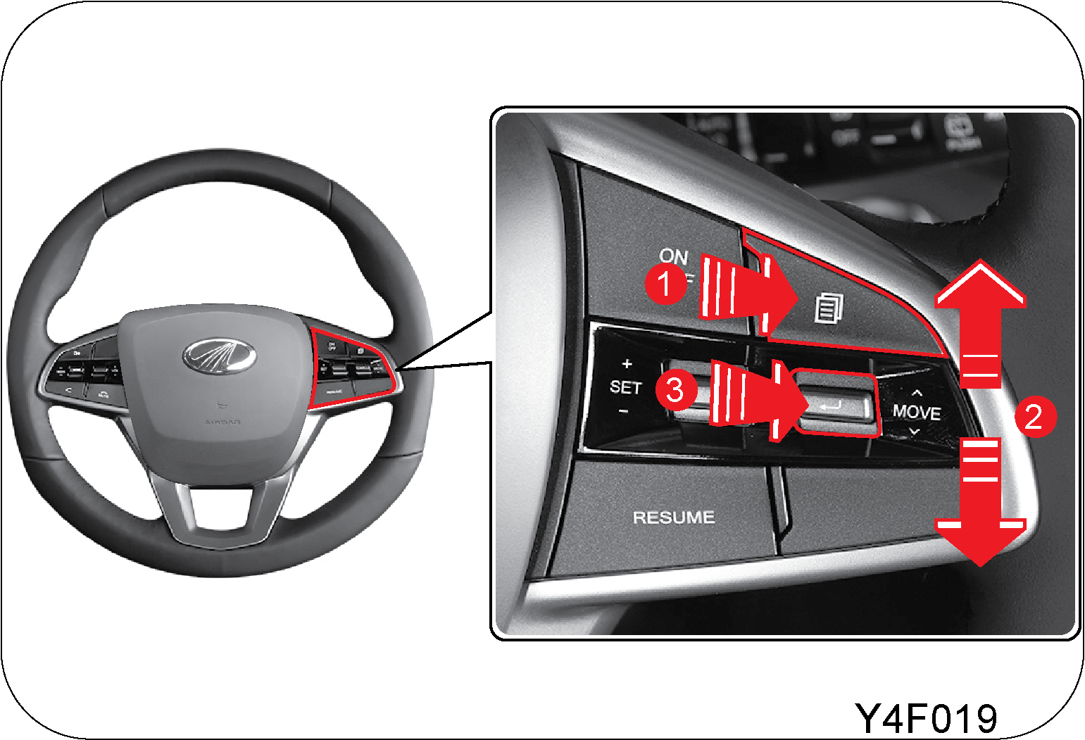
|
Item |
Switch operation |
Function |
|
|
Short press |
Move to main menu |
|
|
Tap up/down |
Navigate through sub modes (menus) |
|
|
Short press |
Enter menu Check settings Select settings |
|
Long press |
Reset selected item Digital speedometer illumination ON/ OFF |
6.5 Main Menu Description
|
Item |
Main menu |
Mode (sub menu) |
||||||||||||||||||||||||||||
|---|---|---|---|---|---|---|---|---|---|---|---|---|---|---|---|---|---|---|---|---|---|---|---|---|---|---|---|---|---|---|
|
|
TRIP computer menu |
|
|
|||||||||||||||||||||||||||
|
|
Digital speedometer menu |
|
|
|||||||||||||||||||||||||||
|
|
AV menu |
|
||||||||||||||||||||||||||||
|
|
User settings menu |
|
|
|||||||||||||||||||||||||||
6.5.1 Trip Computer Menu
Distance to empty/Average fuel economy/Instantaneous fuel economy
 |
 |
Distance to empty
The Distance To Empty (DTE) displayed on the LCD screen is a calculated value based on the measured fuel volume in the fuel
tank, average fuel economy, and information about the driving pattern. The display range is from 0 to 1500 km. If the remaining
distance is less than 50 km, “---“ symbol will blink on the display.
For supervision type, the colour of the DTE value displayed on the screen will change to yellow if the value becomes 100 km
or less, and the “----” symbol will be displayed in red.
The actual amount of fuel remaining in the fuel tank may differ from the amount estimated by the trip computer depending on
the driving conditions of the vehicle and whether the vehicle is level or not. That is, the DTE is only for reference. It
is recommended to refuel before the fuel warning light comes on.
Average fuel economy
This mode indicates the average fuel economy computed based on the total amount of fuel used and the distance driven since
the reset to (--.--). This value shows how far the vehicle could go (in km) with one litre. This value will be updated every
10 seconds on the display. The average fuel economy is calculated continuously as long as the engine is running regardless
of the vehicle movement.
Instantaneous fuel economy
The instantaneous fuel economy is calculated based on the distance driven and the amount of fuel used. This value is displayed
when the vehicle is driven at 10 km/h or more and the value is between 0 and 30 km/L.
Reset: Average fuel economy
Press and hold the (8 ) switch in current mode. The value will be reset and “--.--” will be displayed. Drive for a few miles so that the average
fuel economy values since the last reset are shown again. You can reset this value at the time of IGN OFF, IGN ON, or refuelling
depending on the vehicle settings.
You can select options for resetting the average fuel economy under "Instrument cluster User settings menu → Instrument cluster
settings & information.
Mileage (A), (B)/Average vehicle speed/Driving time
 |
 |
 |
 |
Individual trip mileage (km), average vehicle speed (km/h), driving time (hh:mm) are displayed.
Trip (A, B)
Maximum number of kilometres is 9999.9 km. The value outside this range returns to 0.0 km.
Average speed (A, B)
The average vehicle speed is calculated based on time and distance. This value will be updated every 10 seconds on the display.
Driving time (A, B)
The display range is 00:00 to 99:59. The value outside this range returns to 0:00.
Reset: Trip (A, B), Average speed (A, B), Driving time (A, B)
Press and hold the (8 ) switch in current mode. The average speed will be reset to “---”, and the driving time will be reset to “0:00”.
After departure
 |
 |
Distance driven after the engine start (km), departure time (hh:mm), driving time (hh:mm), fuel consumption (L) are displayed.
After departure
Total distance driven accumulated since the last engine start. Maximum number of kilometres is 9999.9 km.
Departure time
When the engine is started, the time on the left bottom of the LCD screen is displayed here.
Driving time
The display range is 0:00 to 99:59. The value outside this range returns to 0:00.
Fuel consumption
Total amount of fuel used since the last engine start (unit: L).
Reset: After departure, Departure time, Driving time, Fuel consumption
These values will be automatically reset when the engine is started again after the ignition is turned off.
Clock mode

This only applies to the supervision instrument cluster, and the time on the left bottom of the LCD screen is displayed in
analogue format.
Tyre pressure (TPMS)
 |
 |
 |
 |
| • | This message is displayed when the tyre pressure is normal |
| • | If the tyre pressure is normal, "Tyre pressure normal" is displayed |
| • | If the tyre pressure is abnormal, corresponding message will be displayed. The message can blink or stay on depending on the tyre conditions |
6.5.2 DEF Level
|
Supervision |
Standard |
 |
 |
Displays the remaining amount of DEF solution. The DEF inlet is located at the same position as the fuel filler.
| • | For the supervision type instrument cluster, 1 to 2 levels of DEF are displayed in red and 3 levels or higher in blue. |
| • | The volume of DEF tank used in this vehicle is maximum 25 liters and the volume displayed on the instrument cluster is maximum 20 liters. |
Warnings and beeps occur in three stages depending on the remaining amount of the DEF. If it happens, replenish the DEF immediately
so that it does not affect the operation of the vehicle.
The followings are situations for each warning level:
1. Level 1 warning
- Occurs at drivable distance of 2,400 km to 800 km.
- Beep and warning message occur for 10 seconds every 200 km of driving or 4 hours.
2. Level 2 warning
- Occurs at drivable distance of 800 km to 0 km.
.- Warning lamp/beep/warning message occur continuously.
- This warning continues until the enough amount of DEF is replenished.
- The actual drivable distance depends on the driving style.
3. Level 3 warning
- Occurs at drivable distance of 0 km where the DEF is depleted.
- Warning lamp/beep/warning message occur continuously.
- At this level of warning, it is impossible to operate the vehicle. Replenish with 10 liters DEF immediately or have it inspected
and serviced by Mahindra Authorised Dealer or Mahindra Authorized Service centre.
6.5.3 Digital Speedometer Menu
 |
 |
 |
 |
The vehicle speed measured by the speedometer is shown in digital display. Pressing the (8 ) switch turns off all lights except for the LCD screen light.
If you return to main menu, change the mode, press the (8 ) switch, or an event message pops up, the previous lighting conditions are restored.
6.5.4 AV Menu
 |
 |
Linked with AV system
The instrument cluster is linked to the AV system. Therefore, the contents displayed on the AV system are also displayed on
the LCD screen of the instrument cluster. The main menu logo at the top of the screen may vary depending on the manufacturer
of the device connected to the system.
|
|
Radio mode |
|
|
AUX mode |
|
|
DAB mode |
|
|
i-Pod mode |
|
|
Bluetooth music play mode |
|
|
USB |
|
|
USB/SD photo mode |
|
|
Bluetooth (handsfree) mode |
|
|
Android Auto |
|
|
Apple Carplay mode |
|
|
USB/SD video mode |
|
|
USB/SD music mode |
6.5.5 User Settings Manual
|
User settings menu |
Level 1 |
Level 2 |
||||||||||||
|---|---|---|---|---|---|---|---|---|---|---|---|---|---|---|
|
Dashboard Lighting |
Individual setting |
Tick (individual) / Not tick (overall) |
||||||||||||
|
Dial/Pointer light |
0 to 20 stages |
|||||||||||||
|
LCD light |
0 to 20 stages |
|||||||||||||
|
? HELP |
||||||||||||||
|
Language |
English |
한국어 / English / Türkçe / Pусский / 中文 / Nederlands / Español / Deutsch / Français / Italiano |
||||||||||||
|
? HELP |
||||||||||||||
|
Door/ Tailgate |
Auto Lock |
|
||||||||||||
|
Auto Unlock |
|
|||||||||||||
|
Auto Lock speed setting |
|
|||||||||||||
|
Door/ Tailgate |
Auto Lock time setting |
|
||||||||||||
|
Lock/Unlock sound |
Tick/not tick |
|||||||||||||
|
Two Press Unlock |
Tick/not tick |
|||||||||||||
|
Smart door Auto Lock |
Tick/not tick |
|||||||||||||
|
Smart key Window ON/OFF |
Tick/not tick |
|||||||||||||
|
Power tailgate |
|
|||||||||||||
|
Smart tailgate |
|
|||||||||||||
|
? HELP |
||||||||||||||
|
Light |
Leaving - home Headlamp |
|
||||||||||||
|
Coming - home Headlamp |
||||||||||||||
|
Approach lamp |
|
|||||||||||||
|
AUTO Approach lamp |
||||||||||||||
|
? HELP |
||||||||||||||
|
Convenient Features |
Reverse Mirror tilt (Driver) |
OFF, 2°, 3°, 4°, 5° |
||||||||||||
|
Reverse Mirror tilt (passenger) |
OFF, 2°, 3°, 4°, 5° |
|||||||||||||
|
Convenient Features |
Steering wheel alignment alert |
|
||||||||||||
|
Wiper mode indicator |
Tick/not tick |
|||||||||||||
|
Light mode indicator |
Tick/not tick |
|||||||||||||
|
? HELP |
||||||||||||||
|
Sound |
Turn signal sound |
5 different sounds |
||||||||||||
|
Turn signal sound volume |
Level 0 to 3 |
|||||||||||||
|
Parking assist sound |
5 different sounds |
|||||||||||||
|
Parking assist sound volume |
Level 0 to 3 |
|||||||||||||
|
Welcome & Goodbye sound |
Tick/not tick |
|||||||||||||
|
? HELP |
||||||||||||||
|
Checkup Alert |
Activated checkup alert |
Tick/not tick |
||||||||||||
|
Oil & filter |
Not set to 99,500 km (increase by 500 km) |
|||||||||||||
|
Tyre |
Not set to 99,500 km (increase by 500 km) |
|||||||||||||
|
Others |
Not set to 99,500 km (increase by 500 km) |
|||||||||||||
|
? HELP |
||||||||||||||
|
Dashboard Settings & Info |
Average fuel efficiency AUTO reset |
|
||||||||||||
|
Dashboard Settings & Info |
Fuel economy unit |
Km/L
L/100 km |
||||||||||||
|
Temperature unit |
°C
°F |
|||||||||||||
|
Tyre pressure unit |
psi
kPa
bar
Kgf/cm² |
|||||||||||||
|
Summary |
Tick/not tick |
|||||||||||||
|
Driving info display |
Tick/not tick |
|||||||||||||
|
? HELP |
||||||||||||||
|
Reset All Settings |
Yes/No |
6.6 Messages on LCD Display
|
Items |
Supervision |
Standard |
Display condition |
|||||||||
|---|---|---|---|---|---|---|---|---|---|---|---|---|
|
Welcome sound |
 |
 |
|
|||||||||
|
System check |
 |
 |
|
|||||||||
|
Trip information (Driving info) |
 |
 |
|
|||||||||
|
Service interval alert |
 |
 |
|
|||||||||
|
Instrument cluster settings |
 |
 |
If a vehicle speed greater than 0 km/h is detected after you enter the Cluster Setting menu, LCD display shows this warning
message for 5 seconds. The message is not displayed when selecting settings for the driving assist, instrument cluster illumination,
vehicle warning menus.
|
|||||||||
|
ICE warning lamp |
 |
 |
|
|||||||||
|
Vehicle warning log |
 |
 |
You can view the current warning messages here. No list is provided when there is no warning message. |
|||||||||
|
Smart tailgate indicator |
 |
This description only applies to models with supervision instrument cluster. The smart tailgate indicator is turned on when
the Smart tailgate is enabled under User settings menu > Door/Tailgate, indicating that the smart tailgate can be used.
|
||||||||||
|
Smart key warning |
 |
 |
If you lock the door using the registered smart key with another registered smart key left inside the vehicle and all doors
closed, this message will be displayed for 10 seconds.
|
|||||||||
 |
 |
When 2 or more valid smart keys are detected inside the vehicle with IGN OFF and any door except for tailgate and hood open,
this message is displayed for 10 seconds.
|
||||||||||
 |
 |
LCD display shows this message if no smart key is detected inside the vehicle with the ignition switch ON or engine running. |
||||||||||
|
Smart key warning |
 |
 |
The LCD display shows this message for 10 seconds when the ignition switch is set to ACC position twice without depressing
the brake pedal to inform you that the brake pedal should be depressed when starting the engine.
|
|||||||||
 |
 |
If the ignition switch is pressed and there is no valid smart key detected inside the vehicle, this message is displayed on
the LCD screen for 10 seconds.
|
||||||||||
 |
 |
If the gear selector lever is not in P or N position when you start the engine, this message is displayed on the LCD screen
for 10 sec. to inform you that the gear selector lever should be in P or N position.
|
||||||||||
 |
 |
|
||||||||||
|
Smart key warning |
 |
 |
If the gear selector lever is not in P position when you turn the ignition switch to OFF, this message will be displayed on
the LCD screen for 10 seconds to inform you that the gear selector lever should be in P position to turn OFF the power.
|
|||||||||
 |
 |
If low smart key battery is detected with AUTO LOCK function deactivated, this message is displayed on the LCD screen for
10 seconds.
|
||||||||||
 |
 |
|
||||||||||
 |
 |
This message is displayed for 10 seconds when ignition switch is in ACC for 12 minutes or more or the driver door is opened
with ACC ON to prevent battery discharge.
|
||||||||||
|
Front/rear area detection |
In R Position
 |
Rear PAS (shifting gear selector lever to R with IGN ON)
|
||||||||||
|
In D Position
 |
Front PAS (shifting gear selector lever to D with IGN ON)
|
|||||||||||
|
Door/Hood/ Tailgate opening status |
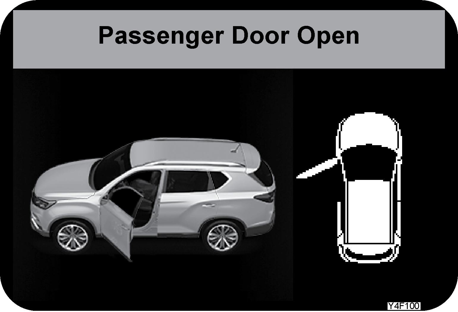    |
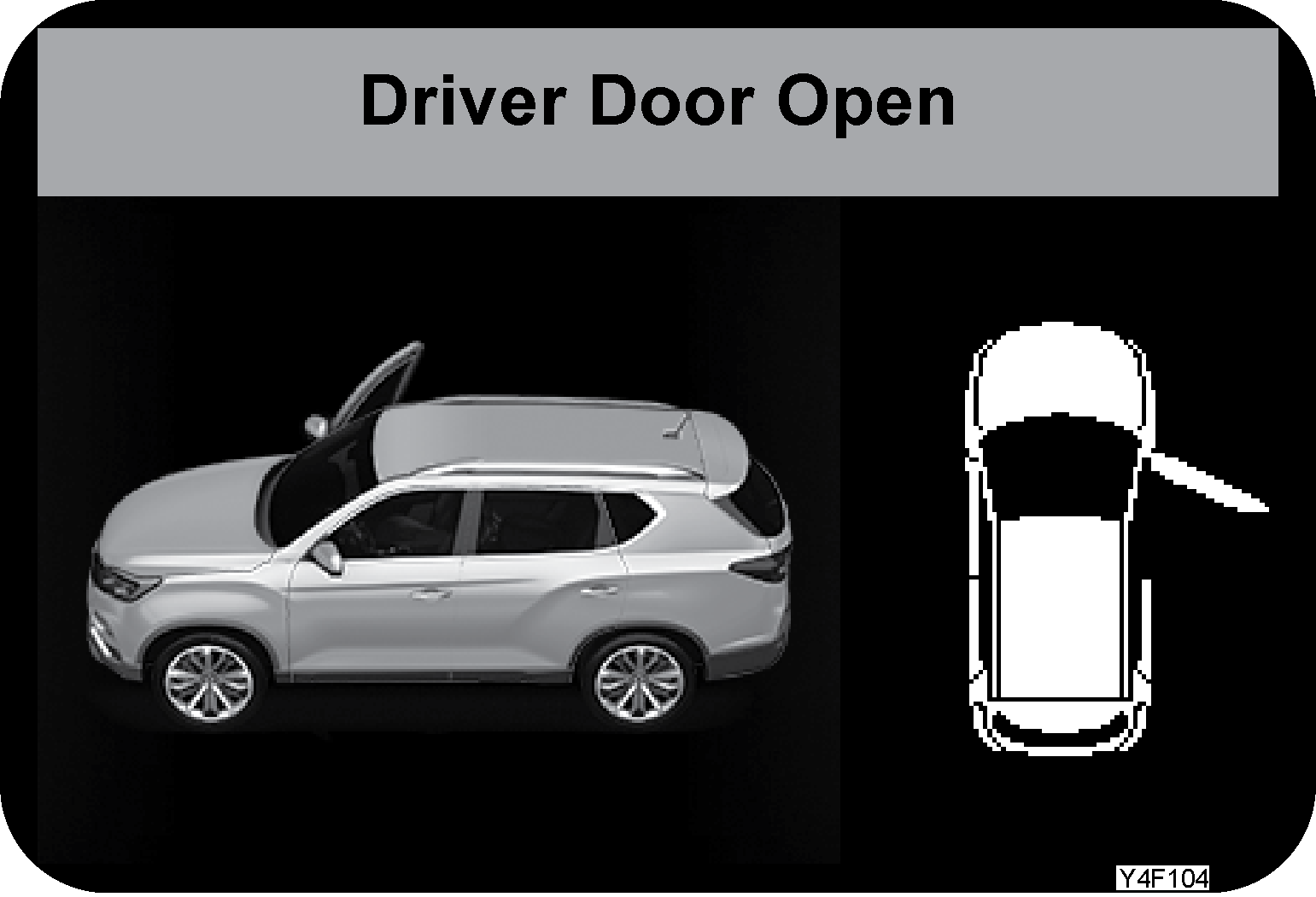   |
Supervision type
Plays animation on the LCD screen when any door, hood, or tailgate is open Standard type
Plays animation on the LCD screen when any door is open. If the hood or tailgate is open, corresponding image on the screen flashes
|
|||||||||
|
Tyre direction |
Left Level 5
 Level 0
 Right Level 5
 |
Left Level 5
 Level 0
 Right Level 5
 |
|
|||||||||
|
Cruise control |
 |
 |
The message is displayed on the LCD screen and the system enters auto cruise ready mode when the cruise control ON/ OFF switch
is pressed with IGN ON.
|
|||||||||
 |
 |
The message is displayed on the LCD screen and auto cruise is activated when the cruise control switch is operated in auto
cruise ready mode.
|
||||||||||
 |
 |
The message is displayed on the LCD screen when the cruise control is switched off with cruise control in READY mode and active
mode.
|
||||||||||
|
AUTO Hold system |
 |
 |
|
|||||||||
|
AUTO Hold system |
 |
 |
This message is displayed on the LCD screen in the following conditions:
|
|||||||||
|
EPB (Electric Parking Brake) |
 |
 |
This message is displayed on the LCD screen when the AUTO HOLD active state is changed to the EPB state. | |||||||||
 |
 |
This message is displayed on the LCD screen in the following conditions: - When the vehicle slips down with AUTO HOLD active and a fault in EPB is detected. - When the vehicle slips down after EPB is activated. If the vehicle slips down, this message remains on the screen until the brake pedal apply is detected. |
||||||||||
 |
 |
- If there is a fault in the EPB system, this message is displayed on the LCD screen along with the flashing EPB warning indicator.
If the message stays on, have the system checked and serviced at a Mahindra Dealer or Mahindra Authorised Service Centre. |
||||||||||
|
EPB (Electric Parking Brake) |
 |
 |
This message is displayed on the LCD screen when the accelerator pedal is depressed with EPB or AUTO HOLD activated and the
AUTO deactivation conditions are not met.
|
|||||||||
|
Rest warning |
 |
 |
The message which recommends taking a break is displayed on the LCD screen for 5 seconds for your safety after driving for
some time. For some time: message displayed every 2 hours starting from the first engine start-up with IGN ON.
|
|||||||||
|
Service interval alert |
 |
 |
This message is displayed once on the LCD screen when the ignition is turned ON from OFF, provided that the check box for
the Service interval alert under the User settings menu is checked and the distance to destination is 0 km.
|
|||||||||
|
Low washer fluid level |
 |
 |
Add washer fluid. If the level of washer fluid is low, Low washer fluid level message along with the corresponding indicator
are displayed on the LCD screen. The remaining volume of washer fluid in the tank when the indicator is activated is about
800 ml.
|
|||||||||
|
Engine system warning |
 |
 |
If there is a fault in the ECU and TCU 3 seconds after the engine start, a warning message and warning indicator are displayed
on the LCD screen.
|
|||||||||
|
Engine oil level check |
 |
 |
If there is a fault in the oil level and oil pressure 3 seconds after the engine start, a warning message and warning indicator
are displayed on the LCD screen.
|
|||||||||
|
ESP system warning |
 |
 |
If there is a fault in the ESP system 3 seconds after the engine start, a warning message and warning indicator are displayed
on the LCD screen.
|
|||||||||
|
EBD system warning |
 |
 |
If there is a fault in the EBD system 3 seconds after the engine start, a warning message and warning indicator are displayed
on the LCD screen.
|
|||||||||
|
ABS system warning |
 |
 |
If there is a fault in the ABS system 3 seconds after the engine start, a warning message and warning indicator are displayed
on the LCD screen.
|
|||||||||
|
Low fuel level |
 |
 |
If the fuel level is detected as being low 3 seconds after the engine start, a warning message and warning indicator are displayed
on the LCD screen.
|
|||||||||
|
Exterior lamp ON alert |
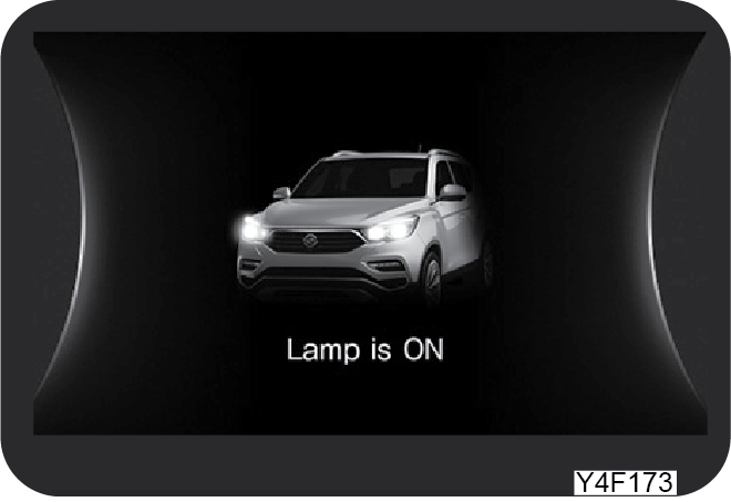 |
 |
This message is displayed on the LCD screen when the exterior lamps are turned on by the opening of the driver door after
IGN OFF.
|
|||||||||
|
Warning due to low DEF level |
 |
 |
The warnings are in displayed in 5 catagories when the DEF system is faulty Each warning is divided into 3 Tiers according to its severity. At 3 Tier, it is impossible to operate the vehicle. If a warning lamp or warning message appears, have the vehicle checked at a Mahindra authorised Service Center. For further information on the warning messages, refer to chapter 7, “EXHAUST GAS AFTERTREATMENT SYSTEM (SCR)”. |
|||||||||
|
Warning due to DEF system (DCU and electrical fault) |
 |
 |
||||||||||
|
Warning due to DEF injection system |
 |
 |
||||||||||
|
Warning due to low quality DEF |
 |
 |
||||||||||
|
Low SCR catalyst purification efficiency |
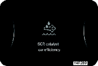 |
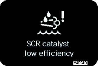 |
||||||||||
6.7 LCD Display Pop-Up Message
|
Items |
Supervision |
Standard |
Display condition |
|||||||||||||||
|
Bluetooth phone call hold |
 |
 |
When there is an incoming call with handsfree phone connected to the vehicle, the caller ID or phone number is displayed on
the upper part of the LCD screen for 5 seconds (priority: ID > phone number)
|
|||||||||||||||
|
HDC ON/OFF |
 |
 |
|
|||||||||||||||
 |
 |
|||||||||||||||||
|
Light mode |
 |
 |
The current light mode between 4 modes, which was selected by the operation of light multifunction switch, is displayed on
the upper part of the LCD screen for 5 seconds.
|
|||||||||||||||
 |
 |
|||||||||||||||||
 |
 |
|||||||||||||||||
 |
 |
|||||||||||||||||
|
Windshield wiper mode |
 |
 |
The Windshield wiper mode between 4 modes, which was selected by the operation of windshield wiper multifunction switch, is
displayed on the upper part of the LCD screen for 5 seconds.
|
|||||||||||||||
 |
 |
|||||||||||||||||
 |
 |
|||||||||||||||||
 |
 |
|||||||||||||||||
|
Rear wiper mode |
 |
 |
The Rear wiper mode between 3 modes, which was selected by the operation of rear wiper multifunction switch, is displayed
on the upper part of the LCD screen for 5 seconds.
|
|||||||||||||||
 |
 |
|||||||||||||||||
 |
 |
7 IN CASE OF EMERGENCY
7.1 Tools Kit and Warning Triangle

 |
 |
|
1 |
Compressor |
5 |
Sealant |
|
2 |
Deflating Button |
6 |
Pressure gauge |
|
3 |
Power Cable |
7 |
Power Switch |
|
4 |
Air Hose |
8 |
Sealant Mounting |

The warning triangle is stored at the bottom of the luggage board.
| • | Set up a warning triangle on a place where it can be very visible while paying attention to traffic conditions |
| • | On a highway or vehicle-designated road, evacuate yourself to a safe place after pulling over your vehicle |
| • | Set up the warning triangle in a position where it is easily identified by the driver of the vehicle approaching from the rear (Set out also a flare at night) |
| • | If your vehicle is operational or the problem is fixed, resume driving paying extra attention to traffic conditions |

When the vehicle has a serious problem during driving
| • | Turn on the hazard warning flasher, stop the vehicle on the shoulder or a safe place and set up the warning triangle in a position where it is easily identified by the driver of the vehicle approaching from the rear |
| • | Have all passengers get out of the vehicle and stay away from the traffic. When your safety is secured, contact your Mahindra Dealer for your emergency service |
7.2 Starting the Engine with Jumper Cable
If the battery is weak or dead, the battery from another vehicle can be used with jumper cables to start the engine.

Connecting order:
| • | The + terminal of the discharged battery |
| • | The + terminal of the booster battery |
| • | The - terminal of the booster battery |
| • | Connect one end of the other jumper cable to the body of the discharged vehicle, such as the engine block or a front towing hook |
The positive (+) cable to the positive (+) terminal.
The minus (–) cable to the minus (–) terminal.
| • | Prepare a set of jumper cables |
| • | Place another vehicle that has the same 12 V of power near to the discharged vehicle |
| • | Switch off all electrical accessories for the discharged vehicle |
| • | Apply the parking brake and shift the transmission to the P position (automatic transmission) |
| • | Connect the jumper cables |
| • | Start the engine in the vehicle which has the booster battery, and let the engine idle for a few minutes |
| • | Attempt to start the engine with the discharged battery |
| • | After starting the engine, carefully disconnect the jumper cables in the reverse sequence of connection |
| • | Connecting the jumper cable to the negative terminal of the discharged battery could result in arcing and possibly a battery explosion. Serious personal injury or vehicle damage can result |
| • | Make sure that the jumper leads are securely connected. Otherwise, an abrupt disconnection due to vibration during engine starting may cause an electrical short resulting in severe damage to electric components |
| • | A battery generates the gas which is flammable and explosive. This gas could be exploded due to the spark when connecting the jumper cables. Make sure that the booster battery has the same voltage rate with the discharged battery |
| • | While connecting the jumper cables, make sure that the negative (–) and positive (+) cables never touch each other. Otherwise, sparks might cause an explosion to the battery |
| • | Battery fluid contains acid that can burn you. Do not allow battery fluid to contact eyes, skin, or painted surfaces. If you accidentally get it in your eyes or on your skin, flush the place with water and contact your doctor |
| • | While being transported in an ambulance, gently wipe out the contacted area with a water-wet cloth or sponge |
| • | When starting your vehicle with jumper cable, turn off the engine of the boost vehicle and connect the jumper cables |
| • | Ensure that the jumper cables are clear away from fan blades before starting the engine |
7.3 When the Engine is Overheating

Symptoms:
| • | The engine overheat warning light blinks (Buzzer sounds) |
| • | The gauge indicates beyond the normal range (or in the red zone) |
| • | Steam or spray from the engine compartment |
| • | Reduced engine output |
Engine Overheat Warning Lamp
Coolant Temperature Gauge
When the engine overheats, steam or spray may come out of the engine compartment. Or, the coolant temperature gauge touches
“H”. If this happens, the engine overheat warning light comes on and a buzzer will sound. Immediately stop your vehicle in
a safe place.
When the Vehicle Overheats
| • | Pull over and stop the vehicle in a safe area. Then shift the gear selector lever to the P position and apply the parking brake |
| • | Turn off the air conditioner or heater if used. Open the engine hood and idle the engine until it cools down |
| • | If you see steam under the hood, stop the engine immediately; If there is no steam, open the hood and leave the engine running in idling speed |
| • | However, if the gauge doesn’t go down to the normal range even in idling, stop the engine and cool it down |
| • | Check the coolant level in the reservoir. If it is too low, check for leaks in the radiator hoses and connections |
| • | Add coolant into the reservoir if necessary |
| • | If necessary, cover the reservoir cap with a cloth and turn the cap a little to release any pressure. After fully releasing the pressure, remove the cap and fill up the reservoir. Then, put the cap back on the reservoir |
| • | If the coolant level is normal, have the cooling system checked by a Mahindra Dealer or Mahindra Authorised Service Center |
7.4 Tyre Pressure Monitoring System (TPMS)
What’s TPMS?
As an additional safety feature, your vehicle has been equipped with a tyre pressure monitoring system (TPMS) that illuminates
an abnormal tyre pressure telltale when one or more of your tyres are significantly under-inflated or over-inflated.

The TPMS ECU receives various data including tyre pressure and temperature from the wheel module mounted to each wheel and
displays the tyre pressure information through the instrument cluster.
Proper tyre pressure : 34 psi
The tyre pressure should be checked when there is nobody inside the vehicle and the tyres are cold (approx. 20°C).
Tyre pressure check

Select TPMS (tyre pressure display) of the instrument cluster main menu (A) to check the tyre pressure of each wheel on the
LCD screen (B).
TPMS starts to recognise the tyre pressures in 5 minutes of continuous driving (over 20 km/h) after starting the engine. If
the system is not ready yet, LCD display shows “--”
| • | The tyre pressure displayed on the LCD screen may be changed by the vehicle driving conditions, number of passengers, tyre inflation, and other external factors |
| • | When inflating the tyre, the tyre pressure may be changed continuously until the turbulent mixing of air with different temperature subsides |
7.4.1 TPMS Warning Light Flashing/ON

This light blinks or stays on when tyre pressure is abnormal or TPMS system (including sensor) is faulty
| • | Faulty TPMS (including sensor): Blinks (for approx. 70 seconds) and stays on |
| • | Tyre pressure abnormality (underinflated / overinflated / flatten): Stays on |
| • | Even with proper inflation of tyre pressure, the TPMS warning light can be illuminated due to the difference between interior and ambient temperatures. This is because the tyre pressure gets lower in proportion to the temperature and does not mean TPMS system is defective |
| • | If you need to drive while the ambient temperature rises or drops sharply, make sure to check and adjust your tyre pressure before driving |
| • | For safe driving, do not depend solely on the tyre monitoring system; instead check your tyre pressure regularly |
| • | If the TPMS warning light comes on in the cluster, stop the vehicle as soon as possible and check the tyres and their pressures |
| • | If the TPMS warning light does not go off after checking tyre pressures and driving for more than 10 minutes with the speed over 20 km/h, have your vehicle checked and serviced at Mahindra Authorised Service Center |
| • | Sudden tyre damages by external factors (nails, road debris etc.) will not be detected immediately. If you feel instability of the vehicle while driving, reduce your speed and move your vehicle to a safe place to check |
| • | Do not remodel or modify your vehicle in any way to avoid interrupting TPMS system operation |
| • | For safety, always use genuine wheels mounted with tyre pressure monitoring system |
7.4.2 LCD Display Regarding TPM
|
Condition |
Supervision |
Standard |
Definition |
|---|---|---|---|
|
Normal |
 |
 |
Tyre pressure is normal |
|
Low pressure |
 |
 |
Tyre pressure is not recognised |
 |
 |
Tyre pressure needs to be checked. Affected tyre symbol comes on |
|
|
Check tyre |
 |
 |
Tyre pressure needs to be checked. Affected tyre symbol blinks for 70 seconds (1s interval) and then comes on |
|
Puncture |
 |
 |
Tyre pressure significantly goes down or tyre is flat. Affected tyre symbol comes on |
|
High pressure |
 |
 |
Tyre pressure is too high. Affected tyre symbol comes on |
|
Imbalanced |
 |
 |
If the pressure difference between LH and RH tyres is 5 psi or more, the corresponding tyres on the screen flash with the
shading inverted alternatively
|
If some tyre pressure is Mahindra Authorised Service Centre shown as “--” symbol, the TPMS wheel module on that tyre may be
faulty. Have your vehicle checked and serviced at a Mahindra Authorised Service Centre.
7.4.3 Tyre Rotation, Tyre Replacement
Tyre Rotation
The TPMS resets the tyre position after tyre rotation. If the vehicle is driven at a speed of 20 km/h or more, the TPMS starts
the tyre position reset procedure. Typically, the reset is completed within 5 minutes.
| • | During the first driving after tyre rotation or replacing a wheel module with a new one (with tyre pressure sensor), previous tyre pressure (value before the change) may be displayed or the TPMS warning light can be turned on |
| • | The tyre position reset time may vary depending on the driving conditions |
When Low Tyre Pressure Detected
| • | The TPMS warning light and the low pressure tyre position indicator on the instrument cluster come on when a significantly under-inflated tyre is detected. If this is the case, slow down and have your vehicle checked and serviced at Mahindra Authorised Service Centre |
| • | If you drive continuously without replacing the under-inflated tyre with a new one, the performance of the vehicle, breaking force and tyre life will be adversely affected and fuel economy will decrease |
Cautions for TPMS
| • | If there is any foreign object, such as snow or mud, caught between the transmitter of wheels and the receiver of vehicle body, strong electric waves or noises affect the TPMS, or a metal object is located near the TPMS antenna, the tyre pressure may be displayed with time delay or may not be displayed normally because of communication or electronic interference |
| • | In some cases, the TPMS does not work properly because the snow chain fitted to the tyres disrupts the communication between the wheel module and TPMS antenna. This does not mean that the vehicle driving is also impaired |
| • | When you are in an area near a facility which emits strong radio frequencies, such as police stations, public offices, broadcasting stations, military facilities, transmitting towers, airports, harbours, the TPMS may fail and the TPMS warning light can be turned on |
| • | If a wheel without wheel module (with tyre pressure sensor) is fitted to the vehicle, the TPMS warning light is turned on and the TPMS does not work |
| • | The service life of the tyre pressure sensor (wheel module) battery inside the wheel may be reduced by frequent tyre pressure abnormality (underinflated / overinflated / deflated tyre/ pressure imbalance) |
| • | Do not rely too much on the TPMS. Always check the tyre pressure before driving off |
| • | When inflating the tyre, the tyre pressure displayed on the air compressor may be different from the tyre pressure read from the TPMS |
| • | The TPMS communicates with the wheel module wirelessly. Therefore, the TPMS may not work properly if there is an electronic device which can cause electronic interference, such as mobile speed camera detector, in the vehicle |
| • | Be careful not to damage the wheel module when replacing the tyres. If the wheel module is subjected to an impact or damaged during tyre replacement, the TPMS may not work at all. If you replace the tyres at a tyre dealer, tell the technician that the tyres have TPMS |
7.5 Cautions When a Tyre is Flat

| • | If a tyre is punctured during driving, turn the hazard warning lamp on immediately, release the accelerate pedal to decelerate the vehicle while holding the steering wheel firmly, and depress the brake pedal lightly to park the vehicle in a safe place |
| • | Place checks in front of and behind the wheel diagonally opposite the flat tyre |
| • | Use the service kit to repair the flat tyre |
| • | Refer to “How to use Service kit” in chapter 6. |
| • | If you are not familiar with repairing flat tires, contact your nearest Mahindra Authorised Service Center for assistance. |
| • | Don't panic! Sharp turning of the steering wheel or abrupt braking may cause a tragic accident |
| • | Do not drive even a short distance after a flat tyre condition. The damaged tyre prevents normal driving and can lead to hazardous conditions |
| • | Turn on the hazard warning flasher, stop the vehicle on the shoulder or a safe place and set up the warning triangle in a position where it is easily identified by the driver of the vehicle approaching from the rear |
| • | If possible, park the vehicle on a flat, solid, and no slippery surface. Repair the tyre with no occupant in the vehicle |
7.6 How To Use Service Kit (Emergency Tyre Repair Kit)
Repair Kit Component
|
|
|
|
1 |
Compressor |
5 |
Sealant |
|
2 |
Deflating Button |
6 |
Pressure gauge |
|
3 |
Power Cable |
7 |
Power Switch |
|
4 |
Air Hose |
8 |
Sealant Mounting |
When to use the Repair Kit

| • | If you have a flat tire, first check the position of the puncture to decide whether or not you can use the repair kit. (Refer to inflating a tire) |
| • | The repair kit can be used only when he puncture size is less than 6mm on tread. |
| • | If the puncture is found on the shoulder or side wall of the tire, do not use the repair kit and obtain help from your Mahindra Authorised Service center for assistance. |
Before using the repair kit, check the side wall/shoulder of the tire to see if it is torn, cracked or damaged. If so, Instead
of using the repair kit, obtain help from Mahindra Authorised Service center.
The service kit is stored in the storage bin (OVM too box) on the left side of the luggage compartment.
 |
 |
Storage Location

Principle of Service Kit

If you have a flat tire, you can put the sealant into the tire using a compressor. After short driving, the sealant will be
applied evenly on the inner surface of the tire and the puncture is sealed by the sealant so that you can drive the vehicle
for a short distance.
| • | Use the service kit only when the hole size on the tread is about 6 mm or less. If the tire sidewall is torn or the hole size is too large, do not use the service kit. Tow your vehicle or take it to a Mahindra Authorised Service Center and have the vehicle serviced. |
| • | If the tire pressure is not increased even when the air is injected using the service kit, stop immediately. And tow your vehicle or take it to a Mahindra Authorised Service Center and have the vehicle serviced. |
| • | When driving with the repaired tire using the service kit, make sure that the vehicle speed does not exceed 80 km/h. |
| • | If you feel or hear any vibrations, unstable steering, or noises, stop he vehicle immediately. And tow your vehicle or take it to a Mahindra Authorised Service Center and have the vehicle serviced. |
| • | The service kit is for emergency use only. Take your vehicle to Mahindra Authorised Service Center as soon as possible to replace the tire repaired using sealant with a new one and check TPMS. (Maximum driving distance allowed after sealant injection: 200 km) |
7.7 Inflating a Tyre
|
|
|
When the tire pressure is low, you can inflate the tire to the specified air pressure using the service kit.
| • | Take out the service kit stored in the storage bin (OVM too box) on the left side of the luggage compartment. |
| • | Take out the air valve and power cable rom the service kit unit. |
| • | Remove the valve cap from the tire, in which the air will be added.
 |
| • | Securely connect the air hose of the kit body to the air valve on the tire. |
The power switch of the service kit should be in OFF position.
 |
 |
| • | Fit the power cable plug of the service kit into the battery terminals / Cigarette lighter socket. |
| • | Start the engine. |
Do not connect the power cable of the service kit to the power outlet to use it. It may cause overload to the power outlet
electrical system, resulting in fire and electric device damage.
| • | Start the engine. |
To avoid a danger of suffocation due to the exhaust gas, start the engine in the well ventilated area.
 |
 |
| • | Press the service kit power switch to activate the compressor. |
To prevent overheating, do not operate the compressor for more than 10 minutes.

| • | Wait until the pressure reaches the specified pressure (34 psi, 2.3 bar) while checking the pressure gauge of the service kit. |
| • | Once the standard pressure is eached, switch off the service kit. |
To measure the tire pressure, switch off The service kit and read the pressure gauge.

| • | If the tire is overinflated, press the air pressure release button (A) to adjust the tire pressure. |
| • | Turn the engine off and disconnect the air hose from the tire. |
| • | Install the air valve cap of the tire. |
| • | Place the service kit back to the original position. |
7.8 Repairing Flat Tyre
|
|
|
If you have a flat tire, repair the tire using a service kit as per the following procedures:
| • | Take out the air valve and power cable from the service kit unit. |
| • | Remove the speed limit sticker from the service kit and affix it on the steering wheel. |

| • | The decal indicates the current tire is sealed by repair kit. You should not drive faster than 80 km/h after the emergency puncture repair kit has been used. |
| • | Check the expiration date for the sealant. The expiration date is marked on the side of the sealant container. Do not use the sealant after the expiration date as it can deteriorate over time. Always read the precautions on the container carefully before using it. |

| • | Connect the air hose (A) of the service kit body to the sealant bottle (B). |
Shake the sealant bottle well before use.

| • | Fix the sealant bottle onto the service kit box firmly. |

| • | Remove the air valve cap of the flat tyre. |
| • | Connect the air hose of the service kit to the air valve on the flat tire securely. |
| • | The power switch of the service kit should be in OFF position. |
| • | If the sealant is injected with loose connection between the air hose of the service kit and the air valve on the flat, the sealant may flow back causing the valve to become blocked. |
|
|
|
| • | Fit the power cable plug of the service kit into the battery terminals / Cigarette lighter socket. |
| • | Start the engine. |
Do not connect the power cable of the service kit to the power outlet to use it. It may cause overload to the power outlet
electrical system, resulting in fire and electric device damage.
| • | Start the engine. |
To avoid a danger of suffocation due to the exhaust gas, start the engine in the well ventilated area.
| • | Press the service kit power switch to activate the compressor. |
To prevent overheating, do not operate the compressor for more than 10 minutes.
| • | Inject the sealant into the flat tire. Wait until the pressure reaches 34 psi while checking the pressure gauge of the service kit. |
| • | Once the standard pressure is reached, switch off the service kit. |
To measure the tire pressure, switch off the service kit and read the pressure gauge.
To prevent overheating, do not operate the compressor for more than 10 minutes. If the tire pressure does not go above 26
psi after 10 minutes, the tire is too damaged to repair using a service kit.
| • | If the tire is overinflated, press the air pressure release button (A) to adjust the tyre pressure. |
| • | Dispose of the used sealant bottle. Prepare a new sealant bottle for later use. |
| • | Be careful not to touch the sealant with your skin when removing the sealant bottle. In the case of contact with skin, wash away the sealant with soapy water. |
| • | The material of the sealant may vary in different products. Using an unapproved sealant, not our genuine one could result in damage of TPMS system sensor. |
Never stand next to the sidewall of the tire when the compressor is operating. Instead, look at the sidewall of the tire.
You may get injured severely in the event of tire rupture.
| • | Disconnect the air hose from the tire nd install the protective cap. |
| • | Install the air valve cap of the tire |
| • | Turn off the ignition, remove the sealant bottle and air hose from the service kit and place the service kit to the original position. |
| • | Immediately drive the vehicle for about 10 km so that the sealant is applied on the inner surface of the tire evenly. |
| • | Stop the vehicle at a safe place and check the tire pressure with the service kit. |
| • | Use the service kit only when the hole size on the tread is about 6 mm or less. If the tire’s sidewall or shoulder is torn or the hole size is too large, do not use the service kit. Tow your vehicle or take it to a Mahindra Authorised Service Center and have the vehicle serviced. |
| • | If the tire pressure is not increased even when the air is injected using the service kit, stop immediately. And tow your vehicle or take it to a Mahindra Authorised Service Center and have the vehicle serviced. |
| • | You should drive with the speed be low 80 km/h if using a tire repaired with the service kit. The maximum distance you could drive with the repaired tire may differ depending n the tire condition, however do not exceed 200 km. |
| • | If steering is unstable or wobbling/noise is felt, stop driving and contact Mahindra service center for help. |
| • | The service kit is for emergency use only. Take your vehicle to Mahindra Authorised Service Center as soon as possible to replace the tire repaired using sealant with a new one and check TPMS. |
| • | Obtain a new bottle of sealant from the dealer with returning the used sealant bottle for disposal. |
7.9 Tyre Pressure Check after Repairing
Check the pressure of the tire repaired with the service kit as follows after driving about 10km.
| • | Take out the service kit stored in the storage bin (OVM too box) on the left side of the luggage compartment. |
| • | Take out the air hose from the service kit box. |
| • | Disengage the air valve cap of the repaired tire. |
| • | Unscrew the protective cap from the air hose and connect the air hose to the tire’s air valve. |
| • | Read the tire pressure displayed on he pressure gauge of the service kit. |
| • | If the value is higher or lower than the specified tire inflation pressure (34psi), adjust it to the specified value Using the air valve. |
If the tire pressure is not maintained at around 34psi, stop driving the vehicle and contact Mahindra Authorised Service Center
for help.
Tyre rotation / Remove need to be done at Mahindra Authorised Service Center. Jack, Tommy & Wheel spanner will not be available
in BS6 vehicle.
7.10 Engine Check Warning Light ON
Engine check warning light
This light turns on when sensors (including automatic transmission) and equipment related with engine control have malfunction.
If this light comes on while driving, have your vehicle checked and serviced at Mahindra Dealer.
| • | If the engine check warning light comes on, the engine power can be reduced and the engine can be turned off |
| • | When the engine overheats because of the low coolant level, immediately turn off the engine and let it cool down |
| • | Opening the reservoir cap should be performed when the engine is off and has cooled down |
| • | Scalding hot coolant and steam could be blown out under pressure, which could cause serious injury. Never remove the coolant reservoir cap when the engine and the radiator are hot |
| • | The engine may be damaged if you add cold water abruptly when the engine is still hot |
| • | Use only Mahindra recommended (antifreeze) coolants |
| • | If the problem continues, have the cooling system checked by a Mahindra Dealer or Mahindra Authorised Service Center |
| • | To avoid being scalded, carefully open the engine hood |
| • | Scalding hot coolant and steam could be blown out under pressure, which could cause serious injury. Never remove the coolant reservoir cap when the engine and the radiator are still hot |
| • | Extremely careful not to contact running parts such as drive belt when the engine is running |
Water in Fuel Warning Lamp
If the amount of water in the fuel filter exceeds the specified level, the warning lamp comes on and chime sounds (with engine
running). If this is the case, stop the vehicle as soon as possible and have the vehicle checked and serviced at a Mahindra
Authorised Service Center.
| • | Driving with this warning light ON can cause serious damage to the fuel system and engine |
| • | If you add inappropriate grade fuel that has a high water content, the warning light of the water separator comes on early. Never use a low quality fuel |
If the amount of water in the fuel filter exceeds the specified level, the warning lamp comes on, a chime sounds or the engine
power decreases.
7.10.1 How to use Priming Pump

| • | Turn the priming pump in open direction while pressing and holding the pump |
Do not use tools like pliers to open or close the priming pump as the pump can be damaged by those tools.

| • | Press the priming pump several times with the pump open until the good amount of fuel flows out of the priming hole |
When pressing the priming pump, pay attention to prevent fuel spray from priming pump hole which may cause injury.

| • | Turn the priming pump in close direction while pressing and holding the pump |
| • | Close the engine hood and start the engine |
7.11 Towing a Disabled Vehicle
 |
 |
Towing with tow truck
The best towing method is to lift the entire vehicle onto the flatbed so that all wheels are off the ground. If it is impossible,
put the front or rear wheels on the jig and tow the vehicle using a dolly, with other wheels off the ground.
For 4WD vehicle
Your vehicle must be towed with a wheel lift and dollies or flatbed equipment with all the wheels off the ground.
| • | The 4WD system equipped vehicle should never be towed with the wheels on the ground. This can cause serious damage to the transmission or the 4WD system |
| • | If your vehicle should be towed due to wheel slips in mud or sand, you can use the towing hooks in your vehicle. However, if the load to hooks is too heavy, the towing hook, rope or chain could be broken, resulting in serious personal injury and vehicle damage |
| • | To prevent damage to your vehicle, proper lifting and towing procedures are necessary. When you need a towing service, contact Mahindra Dealer or Mahindra Authorised Service Center |
For 2WD vehicles
It is not allowed to use a tow truck or keep the rear wheels from moving with the parking brake released for towing, as shown
in the following figure. Do not tow the vehicle with the rear wheels on the ground.

| • | Do not tow with the sling-type equipment or the bumper and lower parts can be damaged |
| • | If the vehicle is towed with the driving wheels on the ground, the transmission may be damaged |
| • | Be careful not to damage the bumper and lower parts during towing |

7.12 Emergency Towing

When towing your vehicle with the towing rope:
| • | Securely tie up the towing rope to the towing hooks. Secure the rope to both of the towing hooks under the front of the vehicle as tight as possible |
| • | To make the rope conspicuously visible, bind a white coloured cloth on the centre of the rope |
| • | Place the gearshift lever in the neutral position and release the parking brake |
| • | Switch on the hazard warning flashers of both vehicles |
| • | Maintain the towing distance. Apply more force to depress the brake pedal of the vehicle that will be towed |
| • | Set the ignition in the ON position |
| • | Total length of the towing and towed vehicle and the towing rope should be less than 25 metres. And tow the vehicle within 25 km with 5 km/h of the towing speed. The length of the rope should be less than 5 metre |
7.12.1 Location of Towing Hooks

| • | The towing hook should be used only for temporary and short distance recovery or towing in an emergency situation. Avoid using it all the time. Misusing can have serious consequences |
| • | Special care should be taken when towing. Avoid an abrupt startoff or reckless driving because it could over-tighten the towing hook, towing rope or chain with excessive force. To prevent damage, do not take up slack in the towing rope or chain too quickly |
| • | If the towing hook is required for towing as the vehicle becomes stuck in snow, mud or sand or it can’t get out by itself due to poor traction, make sure no excessive force is applied to the towing hook. Otherwise, the towing hook, towing rope or chain may be broken, resulting in an injury or damage to the vehicle. For safe towing, it is recommended to contact Mahindra Authorised service Centre or a professional towing company |
| • | If you cannot use a professional towing service, the driver of the towed vehicle should stay behind the steering wheel. But, never use this emergency towing when the electrical system, steering system, or brake system is not operative |
| • | Ensure that only horizontal tension is applied to the front or rear towing hook |
| • | If there are steep hills or sharp turns in your towing path, do not use this method |
| • | Depress the brake pedal stronger than normal condition when the engine is not running |
| • | When your electrical systems operate properly, turn on the hazard warning lamps or turn signal lamps according to the towing vehicle’s signals |
| • | Avoid overloaded towing and do not tow a heavier vehicle than yours |
| • | Position the ESS switch to “ACC” or “ON” so that the steering wheel is not locked |
7.13 When the Engine is Overheating

When the engine overheats, steam or spray may come out the engine compartment. Or, the coolant temperature gauge is closed
to “H”. If this happens, the engine overheat warning lamp comes on and a buzzer will sound. Immediately stop your vehicle
in a safe place.
Symptoms:
| • | The engine overheat warning lamp blinks (Buzzer sounds) |
| • | The gauge indicates over the normal range (or in the red zone) |
| • | Steam or spray from the engine compartment |
| • | Reduced engine output |
7.13.1 When the Engine Overheats
| • | Move off the road to a safe place away from traffic. Park on a firm and level ground. Apply the parking brake and shift the transmission to the P position (automatic transmission) |
| • | Turn off the air conditioner or heater if used. Open the engine hood to ventilate the engine compartment |
| • | If you see steam under the hood, stop the engine immediately. If there is no steam, open the hood and leave the engine running in idling speed |
| • | However, if the gauge doesn’t go down to the normal range even in idling, stop the engine and cool it down |
| • | Check the coolant level in the reserve tank. If it is too low, check for leaks in the radiator hoses and connections |
| • | Add coolant into the reserve tank if necessary |
| • | If necessary, cover the tank cap with a cloth and turn the cap a little to release any pressure. After fully releasing the pressure, remove the cap and fill up the tank. Then, put the cap back on the tank |
| • | If the coolant level is normal, have the cooling system checked by a Mahindra Dealer or Mahindra Authorised Service Centre |
| • | When the engine overheats because of the low coolant level, immediately turn off the engine and let it cool down |
| • | Opening the reserve tank cap should be performed when the engine is off and has cooled down |
| • | Scalding hot coolant and steam could be blown out under pressure, which could cause serious injury. Never remove the coolant reserve tank cap when the engine and the radiator are hot |
| • | The engine may be damaged if you add cold water abruptly when the engine is still hot |
| • | Use only Mahindra recommended (antifreeze) coolants |
| • | If the problem continues, have the cooling system checked by a Mahindra Dealer or Mahindra Authorised Service Centre |
| • | To avoid being scalded, carefully open the engine hood |
| • | Scalding hot coolant and steam could be blown out under pressure, which could cause serious injury. Never remove the coolant reservoir cap when the engine and the radiator are still hot |
| • | Extremely careful not to contact any running parts such as drive belt when the engine is running |
7.14 Accident or Fire

7.14.1 Accident
Turn on the emergency hazard warning switch. If possible, move your vehicle to a safe place to avoid any secondary accidents.
If anyone is injured, call an ambulance and contact the nearest police station
7.14.2 Fire
Stop immediately in a safe place. Turn off the engine. Use fire extinguishers to put out the fire. If it is impossible to
extinguish the fire, contact the nearest fire or police station
If your vehicle catches on fire, don’t panic. Evacuate any occupants and use the extinguisher
| • | In an accident, fuel can be released from the vehicle. Therefore, stop the engine and avoid any sparks or flames |
| • | If you have even a minor burn, see your doctor |
8 MAINTENANCE SCHEDULE AND MANAGEMENT
8.1 Locations in Engine Compartment
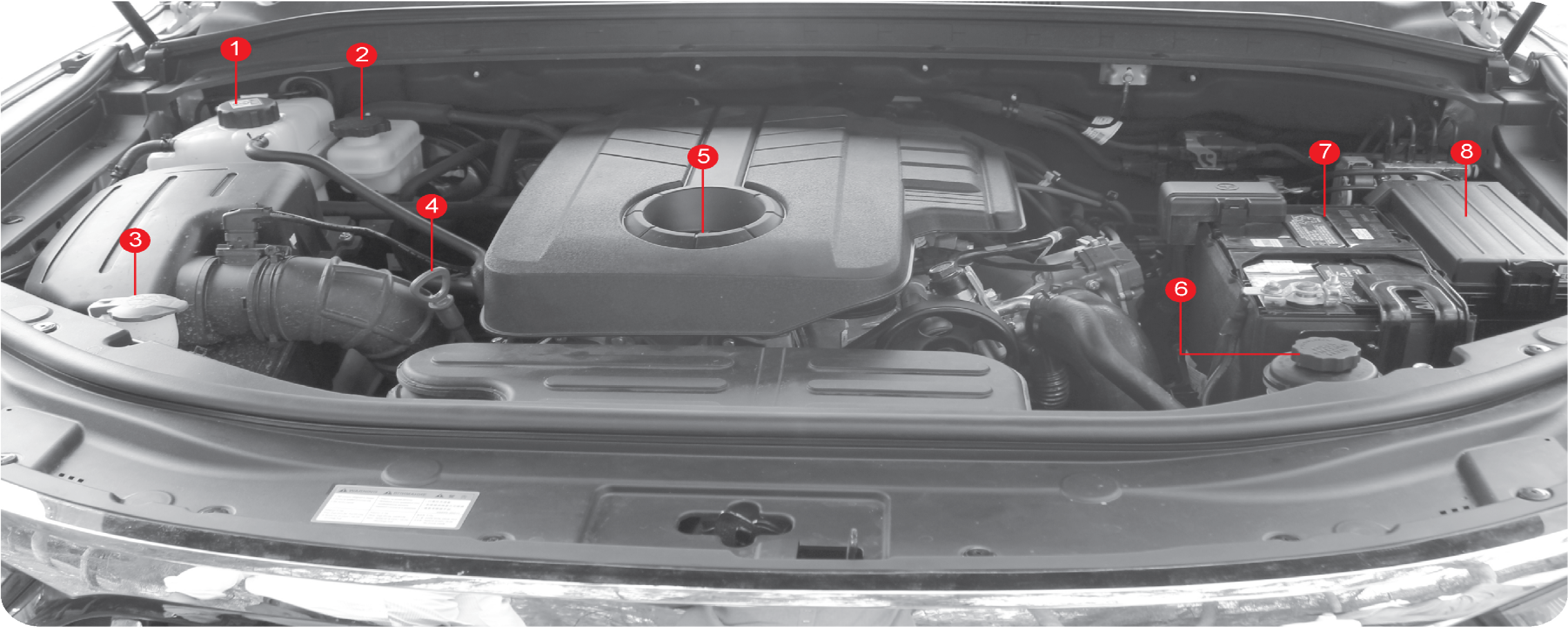 |
|
1 |
Degassing Tank |
4 |
Dipstick |
7 |
Battery |
|
2 |
Brake Fluid Reservoir |
5 |
Engine Oil Cap |
8 |
Fuse and Relay Box |
|
3 |
Windshield Washer Fluid Reservoir |
6 |
Power Steering Reservoir |
| • | Do not work on the engine compartment while the engine, radiator, exhaust manifold, muffler or catalytic converter is hot. Always turn the engine off and allow it to cool before starting the maintenance |
| • | Keep hand clear |
| • | Fan blade start at engine running |
8.1.1 Engine Oil

Level Check
Park the vehicle on a level ground and apply the parking brake. Stop the engine and wait for more than 5 minutes.
| • | Pull it out the dipstick and wipe it out with a clean cloth. Reinsert it all the way |
| • | Pull out it again and check the oil level |
| • | The oil level should be between the maximum (Max) mark and minimum (Min) mark on the oil dipstick. Oil should be replenished before the level goes below the minimum mark |
Replenishment
| • | If the level gets to the lower point, open the filter cap on top of the cylinder block and add the genuine oil without exceeding the level of the upper mark |
| • | Recheck the oil level after 5 minutes |
| • | Regularly check the engine oil level and add Mahindra genuine engine oil if necessary |
| • | Clean the dipstick with clean cloth so that any foreign materials cannot get into the engine |
| • | The oil should not go above the upper mark on the dipstick |
| • | The engine oil may be consumed more if the engine is new |
Operating vehicle with insufficient amount of oil can damage the engine. Make sure the engine oil level is correct and add
oil if necessary.
8.1.2 Function of Engine Oil
Engine oil’s major function is to lubricate and cool the parts inside of the engine, which enables engine to work properly.
When driving at High Engine Speeds
As long as you keep the following with sufficient care in your first running the vehicle, it will guarantee you to get excellent
and comfortable performance for long with your vehicle.
| • | Remember to check the engine oil level and shorten the cycle to refuel the engine oil under severe driving conditions |
| • | Avoid subjecting the engine to heavy loads by driving at full throttle, especially be careful when the outside temperature remains below freezing for the first 1000 km. |
What’s Severe Driving Condition?
| • | Driving at the high engine speed or at high-speed |
| • | Driving for consecutive two hours at high speed |
| • | Driving the rough road, off-road, dirt-laden road, and muddy roads |
| • | Driving in areas where salt or other corrosive materials are being used |
| • | Repeated driving in short-distance |
| • | Driving with the excessive idling |
8.1.3 Engine Care
Observe the following to keep the engine in good condition:
| • | Check the engine oil level frequently under severe driving condition and add some if necessary. The change interval should be shortened as well |
| • | Do not run a new engine at high speed until its driving distance gets 1000 km. Be extra careful when the engine is cold |
| • | After installing a new engine, do not tow another vehicle or a trailer until its driving distance gets 1000 km |
8.1.4 Specification
Use only Mahindra genuine engine oil and filters. Use of non recommended products could cause damage to the engine.
Warnings and Cautions When Checking
| • | Clean the dipstick with a clean cloth so that any foreign materials cannot get into the engine |
| • | Use only the Mahindra genuine engine oil |
| • | The oil should not go above the upper mark on the dipstick |
| • | Operating with insufficient or too much amount of oil can damage the engine |
Regularly check the engine oil level and add the Mahindra genuine engine oil if necessary.
8.1.5 Engine Coolant
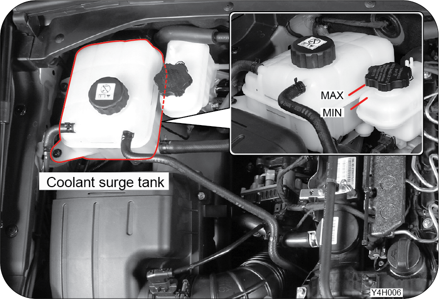
Level Check
Park the vehicle on level ground and apply the parking brake. Stop the engine and wait until it cools.
| • | The coolant level should be between the MAX and MIN mark on the coolant reservoir |
| • | Check the coolant level. If the level is below the “MIN” mark, immediately add coolant |
| • | Do not remove the coolant reservoir cap when the engine and the radiator are hot. The cooling system may spray hot coolant if the cap is removed, causing serious injuries |
| • | Use only the Mahindra genuine coolant and anti-freeze |
Replenishment
| • | Open the coolant surge tank cap slowly when the engine is cold. At this time, you can hear a “hissing” sound |
| • | When there is no more “hissing” sound, remove the cap from the surge tank |
| • | If no unusual things happen, tighten the coolant reservoir cap |
Avoid any direct contact of the coolant to the painted body of the vehicle.
When the coolant level is too low, the engine can overheat. If the coolant temperature gauge in the instrument cluster goes
up abnormally, immediately check the coolant level. Use only the Mahindra genuine coolant and anti-freeze. If different types
of coolants or unapproved coolants are used to refill, chemical reactions can be caused and block the flow of the coolant.
This may cause the engine to overheat or burning inside the engine.
| • | Scalding hot coolant and steam could be blown out under pressure, which could cause serious injury. Never remove the coolant surge tank cap when the engine and radiator are hot |
| • | Use only the Mahindra genuine coolant and anti-freeze |
8.1.6 Fuel Filter
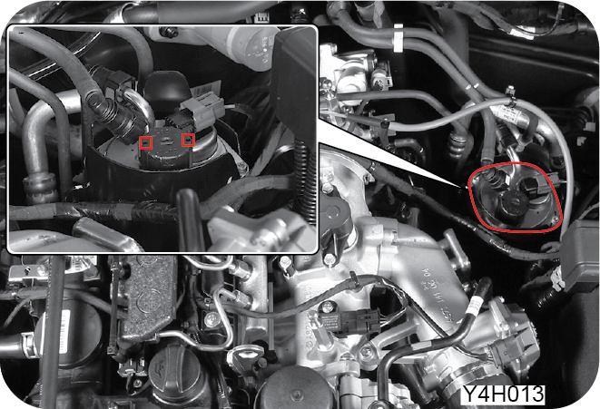
Water in Fuel Separating Function
If water in fuel gets into the engine and fuel system, it may cause serious damage to the fuel system. The fuel filter provides
the water separating function to block the inflow of water. When the water level inside the water separator in the fuel filter
exceeds a certain level, the warning light comes on and the buzzer sounds. If it occurs, have the system checked by Mahindra
Dealer or Mahindra Authorised Service Centre.
Change the fuel filter according to the specified service interval.
Priming Pump Operating Conditions
| 1. | If the vehicle has been run out of fuel |
| 2. | After draining water from the fuel filter |
| 3. | After replacing the fuel filter |
If this happens, pump fuel until the fuel filter is fully filled. Then, start the engine.
After replacing the fuel filter or draining the water from the fuel filter, bleed the air from the fuel filter by using priming
pump. Otherwise, the engine cannot be started or the fuel system could be damaged due to the air in fuel line.
8.1.7 Brake Fluid

Check and Replenishment
| • | The fluid level should be between the “MAX” and “MIN” levels on the reservoir |
| • | Check the level on a level surface. If it drops to or below the MIN mark, refill the tank with the specified fluid. Only use the specified fluid |
| • | Be careful not to let any foreign materials enter the tank when adding the fluid |
| • | Do not add the fluid above the “MAX” level |
| • | Do not allow the fluid to make contact with the body paint work |
| • | After adding the fluid, tighten the cap securely |
| • | If frequent refills are required, have the system checked by a Mahindra Dealer or Mahindra Authorised Service Centre |
| • | Use only the Mahindra genuine brake fluid |
| • | Do not allow the fluid to make contact with skin or eyes. If contact happens, rinse affected areas immediately with plenty of water. If irritation persists, consult a doctor |
| • | The fluid gradually decreases according to brake pad wear. A sudden drop of the fluid level may indicate a leak in the system. In this case, have the system checked by a Mahindra Dealer or Mahindra Authorised Service Centre |
8.1.8 Washer Fluid
Top Up Washer Fluid

Frequently check the washer fluid level and add the specified product as needed.
In winter, use only the specified washer liquid for winter season.
| • | The washer fluid includes flammable materials to prevent freezing. It could cause a fire when directly contacted with flames. When checking the washer fluid, avoid the flames near the washer fluid tank |
| • | If engine oil or antifreeze is used as the washer fluid, it will decrease your visibility through the windshield and may cause an accident |
| • | If you use plain water as washer fluid, it will freeze during the winter and damage the washer fluid reservoir and motor. Use only the specified washer fluid |
| • | If you operate the washer switch without washer fluid, the motor could be damaged due to overloads. Therefore, if there is no washer fluid, do not operate the washer motor |
| • | Operating the wipers on a dry surface on the windshield or rear window without any washer fluid may cause damage to the glass. Operate the wipers after sufficiently spraying the washer fluid |
| • | Avoid any spills of washer fluid on the engine or body paint of your vehicle during replenishment. If washer fluid spills onto your hand or other body part, wash it away under a clean water flow. |
| • | There is no independent washer reservoir for the tailgate window. The front washer reservoir is also for the tailgate window |
8.1.9 Power Steering Fluid
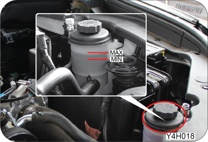
Check the fluid level on a level ground with the engine turned off. The fluid level should be between the MIN and MAX marks
on the reservoir cap gauge. If it drops to or below the MIN mark, refill the reservoir with the specified fluid. Only use
the specified fluid. The difference between the MIN and MAX mark shows fluctuations of the steering fluid between when it
is hot and when it is cold.
In severe cold weather, the viscosity of the power steering oil increases, which can cause temporary abnormal noise at engine
start-up.
8.2 Battery
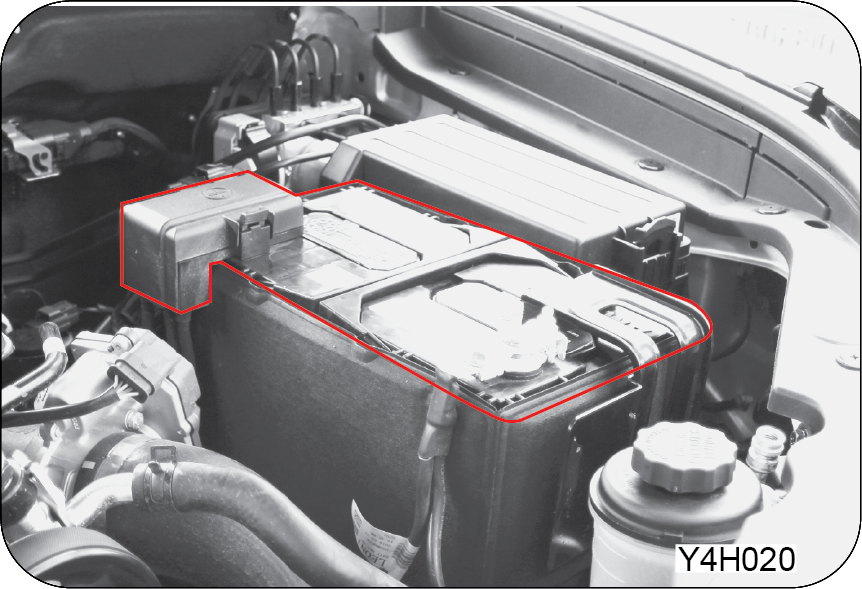
When the battery charge warning light on the instrument cluster comes on, the battery is not normally charging. If the warning
light comes on while driving, turn off all unnecessary electrical devices and have the system checked by a Mahindra Dealer
or Mahindra Authorised Service Centre.
Battery Maintenance
| • | Make sure the terminal connections are securely tightened |
| • | If the terminals are corroded, clean them with a wire brush or sand paper |
| • | The battery terminal should be disconnected only when the ignition key is removed from the key cylinder. Disconnecting the terminal with the key in the “ON” or “ACC” position may cause a sudden change in voltage and damage various electrical systems |
| • | Check the battery for any cracks, damages or leaks. Replace it if necessary. To remove any battery fluid on the battery surface, wear rubber gloves and wipe the fluid out with a wet-soapy cloth |
| • | The battery has acid that can burn you. And its gas can explode. You can get serious injuries if you are not careful. Keep naked flames, sparks and smoking items away from the battery |
| • | Loosely connected battery terminals can set up sparks. These sparks can cause a fire with flammable gas. Therefore, tightly connect the terminals |
| • | At night, if you need to check the engine room, do not use a lighter, but only use a battery-powered flashlight |
| • | Because the battery electrolyte is very strong acid, avoid any direct contact of the battery electrolyte on your skin or vehicle’s body. If the acid contacts your skin, thoroughly wash your skin with fresh water and see your doctor. Do the same on your vehicle |
| • | Wear eye protection when working with a battery. If working in a closed area, keep good ventilation |
| • | If you disconnect the battery terminal when the engine is running, electrical systems could be damaged |
| • | To remove the battery cable, disconnect the negative cable first and be careful on the battery terminal polarity when you connect the cables. The negative and the positive should not be confused |
| • | The polarity of the battery, i.e. the connections for positive and negative cables, must not be interchanged. Never short-circuit the battery |
| • | When the ambient temperature is too low, the battery capacity will drop and can be frozen |
| • | Keep the battery electrolyte at its specified level. If the electrolyte level is higher than the MAX level, it can overflow during battery charging and if the electrolyte is overcharged, the battery can explode |
| • | Only use a battery with the approved voltage and capacity. Otherwise, an incompatible battery can catch fire |
| • | Always use the battery with correct voltage for the vehicle. Otherwise, there is a risk of fire |
| • | Observe the indications on the battery |
| • | Always read the safety instructions in the User Manual before working on the battery |
| • | The battery cell always contains highly flammable hydrogen gas which may explode if ignited. Be sure to keep it away from a cigarette, a spark or other flames |
| • | Wear a protective goggle when charging the battery or performing any work |
| • | In addition, ensure adequate ventilation of the enclosed space |
| • | The battery electrolyte solution contains a highly corrosive sulfuric acid. Be careful not to contact it with skin, eyes, clothes or paint. In particular, keep out of the children’s reach |
| • | When in contact with the skin, wash off the contact area; In case of eye contact, flush with running water for at least 15 minutes, and seek medical help immediately |
| • | The hydrogen gas in the battery is highly flammable and may explode if ignited |
| • | Do not throw out used battery as this pollutes the environment and is hazardous to our health. For environmental protection, properly dispose of used battery at designated disposal sites only |
8.3 Wiper Blade Replacement
Front Wiper

| • | Remove the ignition key and lift the wiper arm up from the windshield |

| • | Press the wiper blade retainer (A) |
| • | Remove the wiper blade by pulling it out in the direction of the arrow (B) |
| • | Instal a new blade |
| • | Put the wiper arm down |
Rear Wiper

| • | Remove the ignition key and lift the wiper arm up from the rear glass |

| • | Lay the wiper blade on its side and remove it by pulling it out in the direction of the arrow |
| • | Install a new blade |
| • | Put the wiper arm down |
| • | Do not open the hood when the wiper arm is lifted up. The wiper and hood may be damaged |
| • | Do not operate the wiper when the washer fluid reservoir is empty |
| • | Be certain not to apply any fluid polish containing oil to the windshield of your vehicle since this will result in streaks which impair vision. Contamination of either the window or the wiper blades with foreign materials can reduce the effectiveness of the windshield wipers. Never clean up the windshield with a waxed or oil-saturated cloth |
| • | Always lift the wiper arm up on the driver side first, and then on the passenger side |
| • | The wiper arm on the driver side may interfere with the one on the passenger side. It is normal |
| • | Malfunctioning wipers on a raining or snowing day may be detrimental to your driving safety. Never drive your vehicle with malfunctioning wipers on a raining or snowing day |
| • | Do not touch the running wipers. It may cause a personal injury |
8.4 Fuse and Relay Box
If any of the electrical system components do not operate, check its corresponding fuse. If the fuse is blown, replace it
with the same capacity.
Fuse and Relay Box in Engine Compartment
 |
 |
Open the engine hood. Release the clips on the fuse and relay box and open the cover.
| • | When an electrical system does not operate, check its fuse first. If a fuse is blown, check its capacity and replace it with the same capacity |
| • | If you remove the fuse when the electrical power is supplying, electrical equipment could be damaged. Turn off all electrical equipment and set the ignition switch to OFF when replacing fuses |
| • | Always replace a specified fuse with the same rating |
| • | If a newly inserted fuse blows again after a short time, have the electrical system checked and repaired by a Mahindra Dealer or Mahindra Authorised Service Centre |
Interior Fuse and Relay Box
 |
 |
The fuse box is located at the left side of the instrument panel. To access the interior fuse box, open the driver’s door
and remove the fuse box cover with your finger.
If you do not use genuine parts or specified light bulb, and if you alter the HID bulb or LED lamp wiring, fuse disconnection,
malfunction and other wiring damages could occur
8.4.1 How to Check and Replace Fuse

| • | Turn off all electrical equipment and set the ignition switch to OFF |
| • | Open the fuse and relay box cover |
| • | Locate the defective fuse |
| • | Pull out the relevant fuse by using the fuse puller |
| • | Visually check whether it is blown or not |
| • | If normal, insert it to its original position |
| • | If blown, check its capacity and replace it with the same capacity |

| • | The use of anything other than the specified fuse could cause damage to the electrical system and even cause a fire |
| • | The use of different types or different rating fuses could cause damage to the electrical system and even cause a fire. Always replace a fuse with the one with the same rating |
The underhood fuse and relay box has some spare fuses. Refill the fuses immediately as you use them. The fuse rating is indicated
on the upper surface of the fuse
8.5 Bulb Specifications and Functional Check
8.5.1 Bulb Specifications
|
Components |
Quantity |
Specification |
|||
|---|---|---|---|---|---|
|
Front side |
Headlamp |
High beam |
2 |
H1-55W |
|
|
Low beam |
Bulb |
2 |
H7-55W |
||
|
HID* |
D8S 25W |
||||
|
Turn signal lamp/Side-marker lamp/DRL |
- |
LED |
|||
|
Front fog lamp |
Bulb |
2 |
H16 |
||
|
LED* |
- |
LED |
|||
|
Cornering lamp |
- |
LED |
|||
|
Side repeater (Secondary turn signal lamp) |
- |
LED |
|||
|
Puddle lamp |
- |
LED |
|||
|
Welcome lamp (Door handle) |
- |
LED |
|||
|
Rear side |
Rear lamp |
Tail (stop) lamp |
- |
LED |
|
|
Turn signal lamp |
2 |
PY21W |
|||
|
Backup lamp |
2 |
W16W |
|||
|
License plate lamp |
- |
LED |
|||
|
High mounted stop lamp |
- |
LED |
|||
|
Interior lamp |
Front room lamp |
- |
LED |
||
|
Centre room lamp |
- |
LED |
|||
|
Luggage room lamp |
- |
LED |
|||
|
Glove box lamp |
1 |
5W |
|||
|
Sun visor lamp |
2 |
5W |
|||
|
Front/rear door courtesy lamp |
4 |
5W |
|||
|
Foot lamp |
2 |
5W |
|||
|
Dashboard lamp (Centre) |
- |
LED |
|||
|
Front/rear inside handle lamp |
- |
LED |
|||
|
Front door trim mood lamp* |
- |
LED |
|||
|
Dashboard mood lamp (Passenger side)* |
- |
LED |
|||
The LED is not replaceable. If LED does not illuminate, replace the lamp assembly with new one.
8.5.2 Functional Check
| • | Check whether the lamp comes on or off by turning its switch |
| • | Check the corresponding fuse when the lamp doesn’t come on |
| • | If the fuse is blown, replace it with a new one. For replacing procedures, refer to the “In Case of Emergency” section in this manual |
| • | If the fuse is not blown, check the bulb and replace it with a new one if needed |
| • | If the bulb is not defective, have the system checked by a Mahindra Dealer or Mahindra Authorised Service Centre |
| • | Use only a specified capacity bulb for replacement |
| • | Disconnect the negative cable on the battery before replacing the bulb. Remove the ignition key |
| • | Do not apply excessive force to remove the bulb cover |
| • | Make sure that the corresponding switch and the ignition switch are turned off before replacing a bulb |
| • | Do not touch a bulb with bare hands immediately after turning off the lamp |
| • | Do not touch a bulb with bare hands. Fingerprints, dust, or moisture stuck to the bulb may shorten its life or cause it to explode. If you accidentally touch the bulb, wipe the bulb glass with a soft cloth |
| • | Never try to adjust the headlamp aiming angle. It should be done by a qualified technician in a Mahindra Dealer or Mahindra Authorised Service Centre |
8.6 Location of Exterior Lamps
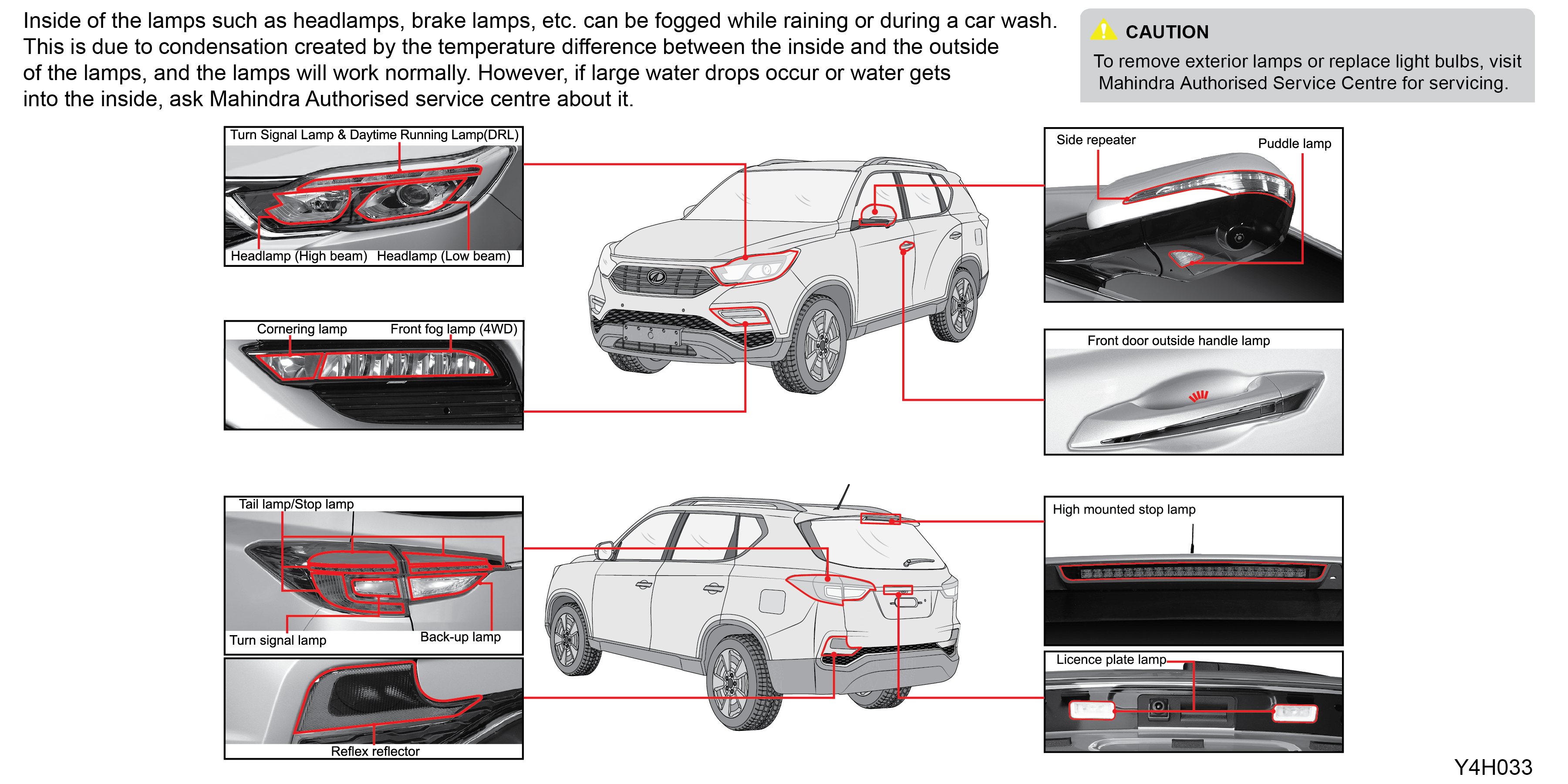 |
8.6.1 HID (High Intensity Discharge) Headlamp
| • | HID headlamp bulb is better than regular (halogen) bulb in terms of performance and lifetime; however, frequent switching (ON/OFF) of headlamp may shorten the life |
| • | Unlike regular (halogen) light bulb, HID headlamp bulb slowly dims when turning on the headlamp even after the bulb ran out. Therefore, if the HID headlamp turns off and comes on again with the headlamp switch ON, the light bulb needs to be replaced |
| • | HID headlamp is more complex than regular (halogen) headlamp, so an extra charge will be applied when replacing |
| • | When removing/installing the HID headlamp bulb and unit, the angle adjustment (up/down, right/left) should be performed. Visit our Mahindra Authorised Service Centre and ask about it |
| • | Characteristics of HID headlamp bulb |
| • | The colour of the light changes during its initial lighting through 4 seconds later until stabilised |
| • | Colour change by the usage period is an unique characteristic of HID bulb |
| • | Initial stage: light yellow |
| • | Over 100 hours: light blue |
| • | Over 1,000 hours: blue |
| • | Late stage: bright red, purple, get dark |
| • | While driving a vehicle equipped with HID headlamp, the levelling switch should be used depending on the number of passengers and loading condition so that the lamp does not interrupt other drivers’ views |
| • | If the light does not come on while operating HID type of headlamp (low beam), more complex actions than fuse/relay replacement needs to be taken. Therefore, visit Mahindra Authorised Service Centre for overall inspections of related systems |
| • | Never remove nor disassemble any parts of HID headlamp (projector, high voltage cable, ballast) to avoid serious injuries due to an electrical shock |
| • | It is dangerous to contact your body part to the vehicle equipped with HID headlamp due to the high voltage direct current flowing through the system. Besides, more actions than bulb replacement should be performed. Therefore, ask Mahindra Authorised Service Centre if malfunction occurs |
| • | If discretionally modifying the vehicle equipped with regular headlamp to HID headlamp, the system will underperform or be overloaded causing malfunction of the vehicle Additionally, the light will interrupt the driver’s view running on opposite side of the road resulting in deadly accident |
8.7 Replacing Air Conditioner Filter
Replace the Air Conditioner Filter when:
| • | Unpleasant odour is generated at the first operation after a long unused period |
| • | Cooling and blowing capacity have decreased |
| • | Make sure to remove the glove box holder with care. If excessive force is applied to it, it can be deformed and the glove box cannot be securely mounted |
| • | When replacing the A/C filter, make sure the direction of the filter is not changed |

| • | Open the glove box by pressing the open switch |

| • | Pull the holder in the direction of the arrow shown in the picture to remove it on each side |
| • | When the filter is contaminated, it will decrease the cooling or heating capacity of the system and create unpleasant odours |

| • | Disengage the damper clip at the right bottom side of the glove box |

| • | Remove the A/C filter cover by pressing the right side of the A/C filter cover |

| • | Remove the A/C filter cover |

Replace the A/C filter with a new one. Instal in the reverse order of removal

When installing the A/C filter, AIR FLOW with a mark "↓” should face downward
8.8 Tyre
8.8.1 Tyre Inflation Pressure

Tyre Inflation Pressure
|
Type |
Tyre |
Wheel |
Tyre Inflation Pressure |
|
Driving Tyre |
255/60R18 |
7.5JX18 |
34 psi |
Wheel Alignment and Balance Between Tyre and Wheel
If the wheels are not aligned as specified, it leads to uneven and faster wear of tyre and the vehicle pulls to one side.
If the wheels and tyres are not balanced, it could result in uneven wear of tyre and vehicle vibration. If the above symptoms
occur, immediately stop driving and have the vehicle checked at a Mahindra Dealer or Mahindra Authorised Service Centre.
| • | Maintaining the specified tyre pressure is essential for comfortable riding, driving safety, and long tyre life. Incorrect inflation pressures will increase tyre wear and will impair safety, vehicle handling, comfortable driving and fuel economy. Always make sure that the tyre inflation pressure is correct |
| • | Check and adjust the tyre inflation pressure, prior to any long journey (before the tyre is heated up) |
The tyres should be checked before they are heated up using an tyre pressure gauge. Increase the tyre inflation pressure by
4~5 psi from the specified value prior to any long journey.
8.8.2 Tyre Sizing Chart

|
Load index |
Speed index |
||
|
Symbol |
Maximum Load (kg) |
Symbol |
Maximum speed (Km/h) |
|
102 |
850 |
S |
180 |
|
104 |
900 |
T |
190 |
|
106 |
950 |
U |
200 |
|
108 |
1,000 |
H |
210 |
|
110 |
1,060 |
V |
240 |
|
112 |
1,120 |
Z |
Over 240 |

Tyre Date of Manufacture
In general, all tyres should be replaced after six years from the date of manufacture regardless of the remaining tread.
You can check the date of manufacture by looking for the DOT Tyre Identification Number (TIN). The last 4 digits of TIN indicates
the date of manufacture with the front 2 digits representing the week and the last 2 digits representing the year in which
the tyre was manufactured.
Temperature Inside the Tyre
The temperature inside the tyre increases during driving.
Overloaded vehicle, low tyre pressure or driving at a high speed creates more heat and the heat builds in the tyre. The limit
temperature of tyres is about 125°C. If the temperature exceeds this limit, the adhesion between the underlying layers of
tyre is significantly reduced, and this may result in an accident. Always maintain correct tyre inflation pressure specified
by the manufacturer and take a break every 2 or 3 hours of highway driving.
The temperature inside the tyre drops about 20°C for 10 minutes of vehicle stationary.
8.8.3 Tyre Wear Check

The tyres on your vehicle have built-in tread wear indicators that appear between the tread grooves. The tyre should be replaced
when the wear indicators appear in two or more adjacent grooves.
| • | Driving on worn or damaged tyres is very dangerous and may cause an accident. Also, a damaged tyre could burst |
| • | Check tyres regularly for any damage (foreign objects, punctures, cuts, cracks, bulges in side walls) and replace if necessary. |

8.9 Do-it-Yourself Operation
| • | Be careful not to touch any hot components such as the engine, radiator, exhaust manifold, catalytic converter, or muffler when the engine is just stopped. They may burn you badly. Let the engine cool down before any service |
| • | When working with the battery or fuel-related components, always stop the engine and do not smoke. Also, remove all flames or sparks near the vehicle |
| • | Do not connect and disconnect the battery terminals when the ignition key is in the “ON” position |
| • | The polarity of the battery, i.e. the connections for the positive and negative cables, must not be interchanged |
| • | The battery cables and wires transfer high voltage and current. Avoid any short circuit |
| • | Make sure that the ignition key is “OFF” when performing any work in an enclosed space such as a garage |
| • | Keep the used oil and coolant out of reach of children. (For a proper disposal of them, contact a professional service.) |
| • | When checking your vehicle, you must turn off the engine first. Then, put the shift lever into the “P” (automatic transmission) |
| • | The electrical cooling fan can start to operate unexpectedly even when the engine is stopped. Disconnect the negative battery cable before you check the radiator, cooling fan or nearby parts |
| • | Check the level of the engine oil and every fluid including coolant daily. If you drive while the fluid levels are low, your vehicle can be damaged and such damages will not be covered by warranty |
| • | Use only the genuine Mahindra oils and fluids |
| • | Do not allow oils and coolant to make contact with skin or painted surfaces during inspection or refill of them. They can also damage paint finish. If skin contact happens, rinse affected areas immediately with plenty of water and then consult a doctor |
| • | Do not overfill the oil or coolant, otherwise the engine and transmission may be damaged. Maintain the specified level |
| • | The performance of oils and coolant may be deteriorated when they are exposed to dust and moisture. Be careful not to allow contact with dust while refilling |
| • | In spite of very limited driving of your vehicle, oils and other fluids can disappear over the time. Therefore, check their levels frequently |
| • | Improperly disposed engine oil and/or other fluids can pollute the environment. Dispose used fluids in accordance with local environmental regulations |
| • | When performing any inspection or maintenance work on your vehicle, always take care to prevent serious accidental injury to yourself or damage to the vehicle |
8.10 Emission Reduction Device
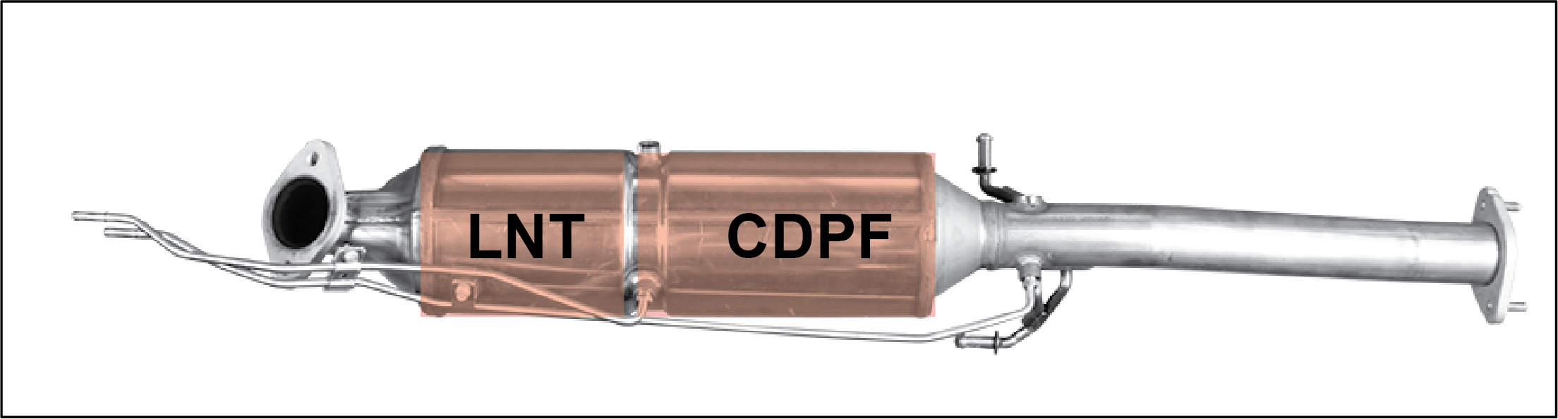
This vehicle is equipped with the Diesel Oxidation Catalyst (DOC) and Diesel Particulate Filter (DPF) for emission reduction
devices.
The DOC converts HC and CO2 in the fuel to H2O and removes 80% of the Soluble Organic Fraction (SOF) among particulate materials,
thereby reducing 25% or more of particulate materials.
The DPF collects particulate materials to the filter and removes them by combustion. This device removes 95% or more of particulate
materials.
Catalyst Diesel Particulate Filter (CDPF)
The CDPF is a compound word for Diesel Oxidation Catalyst (DOC) and Diesel Particulate Filter (DPF), which are exhaust gas
after-treatment devices.
LNT (Lean NOx Trap) CDPF (Catalyst Diesel Particulate Filter)
The LNT (Lean NOx Trap) CDPF (Catalyst Diesel Particulate Filter) is a system to eliminate the nitrogen oxide from exhaust
emissions. Use the specified fuel to avoid exhaust smell due to the poor quality fuel and to maintain the normal performance
of the LNT DPF.
Regeneration Process
“Regeneration” is the process of combusting particulates when a certain amount of particulates is collected in the filter.
In this process, the temperature of exhaust gas rises to approx. 600°C by fuel control and particulates are effectively incinerated.
When the Engine CHECK Indicator Flashes
Regeneration may not be performed due to several operating conditions. And in this case, the engine CHECK indicator flashes.
This flashing function is to inform the driver to take action for the proper regeneration of the filter.
If the engine CHECK indicator flashes, drive the vehicle at over 80 km/h for 20 minutes to regenerate the DPF. When the amount
of particulates is lowered down to a certain limit, the engine CHECK indicator goes off.
| • | The vehicle equipped with DPF system may generate the white smoke when using the fuel with high sulfur content (over 100 ppm). This is caused by the sulfur attached and accumulated n DPF. However, this is very natural situation, not caused by your vehicle. |
| • | How to fix the problem: Replace current fuel with high grade fuel as soon as possible. However, even after replacing the fuel, the white smoke may be seen due to residual sulfur in DPF system. For safety driving, have the system checked at Mahindra Authorized Service enter. |
| • | The presence of an excessive amount of particulates in the DPF may reduce the engine power. |
| • | An excessive amount of accumulated particulates can damage the DPF. Therefore, make sure to drive the vehicle at 80 km/h or more for 20 minutes at every 500 km. |
| • | When the engine CHECK indicator comes on, it means that a sensor related to the engine control or an electric device is malfunctioning. In this case, have your vehicle checked by a authorised Mahindra Dealer. |
| • | The engine CHECK indicator blinking means an excessive amount of particulates accumulated in the DPF. If this happens, you must drive the vehicle at the speed of 80 km/h or higher for 20 minutes. If you keep driving the vehicle at the speed of less than 80 km/h without following this instruction, it may cause damage to the exhaust system related to the DPF. |
| • | The regeneration process of the DPF produces so much heat, so never drive or stop the vehicle near flammable materials to avoid causing fire. Also, be sure to stay away from the exhaust pipe and the DPF to avoid getting burned. |
8.10.1 Exhaust Gas After treatment System (SCR)
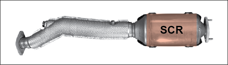
Our exhaust gas aftertreatment system has the DEF system (SCR, Selective Catalytic Reduction), which consists of the DEF injection
system and SCR catalyst, to reduce NOx remaining in the exhaust gas
8.10.2 Low DEF Level Warning
The low DEF level warning occurs in 3 stages depending on the distance the vehicle can be driven with the remaining DEF.
The DEF consumption may depend on the driving style and surrounding environment.
If you are operating the vehicle continuously without replenishing DEF with the warning message displayed or the warning lamp
lit, it may cause serious damage to the DEF solution system or make it impossible to operate the vehicle. In such cases, be
sure to replenish the DEF solution immediately or have it inspected and serviced by Mahindra Authorised Dealer.
Level 1 warning
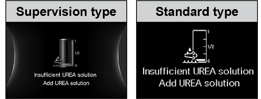
| • | Warning lamp: not lit |
| • | Warning beep: sound |
| • | Warning message: displayed |
| • | Drivable distance at when warning occurs: 2,400 km to 800 km |
| • | Occurs for 10 seconds every 200 km of driving or 4 hours |
Level 2 warning
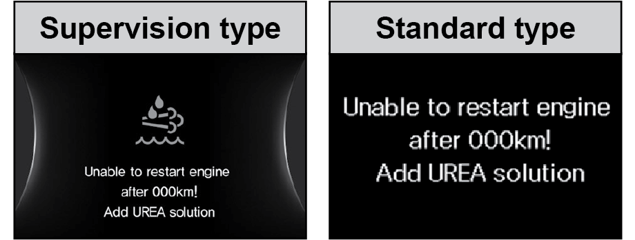
| • | Warning lamp: lit |
| • | Warning beep: sound |
| • | Warning message: displayed |
| • | Drivable distance at when warning occurs: 800 km to 0 km |
| • | Continues until enough amount of DEF is replenished. |
Level 3 warning
| • | Warning lamp: lit |
| • | Warning beep: sound |
| • | Warning message: displayed |
| • | Drivable distance at when warning occurs: 0 km (impossible to operate vehicle) |
| • | Impossible to operate the vehicle because DEF is depleted. Replenish the DEF immediately. |
|
Item |
Supervision |
Standard |
Operating conditions |
|---|---|---|---|
|
Warning due to low DEF level |
 |
 |
- Warning lamp (not lit), warning beep (sounds), warning message (displayed)
- Drivable distance at when warning occurs: 2,400 km to 800 km
- Occurs for 10 seconds every 200 km of driving or 4 hours.
- Immediately replenish at least 10 liters of DEF when corresponding warning is issued. (warning lamp turned off) |
 |
 |
- Warning lamp (lit), warning beep (sounds), warning message (displayed)
- Drivable distance at when warning occurs: 800 km to 0 km
- Immediately replenish at least 10 liters of DEF when corresponding
warning is issued. (restart restriction lifted and warning lamp turned off) |
|
|
|
 |
- Warning lamp (lit), warning beep (sounds), warning message (displayed)
- Drivable distance at when warning occurs: 0 km (impossible to operate vehicle)
- Impossible to operate the vehicle because DEF is depleted. Replenish the DEF immediately. |
8.10.3 How To Disable Restart Protection
If a Tier 2 warning is issued due to low DEF level, engine restart may be restricted.
In such cases, immediately replenish at least 10 liters of DEF
If engine restart is restricted and you can’t operate the vehicle when any warning is issued (other than warning due to low
DEF level), have the vehicle checked at a nearest Mahindra Authorized Service Center.
8.10.4 DEF / SCR Alerts
|
Item |
Supervision |
Standard |
Operating conditions |
|---|---|---|---|
|
Warning due to DEF system (DCU and electrical fault) |
 |
 |
- Warning lamp (lit), warning beep (sounds), warning message (dis-played)
- Corresponding first warning is displayed for 50 km of driving when the DEF system is faulty. |
 |
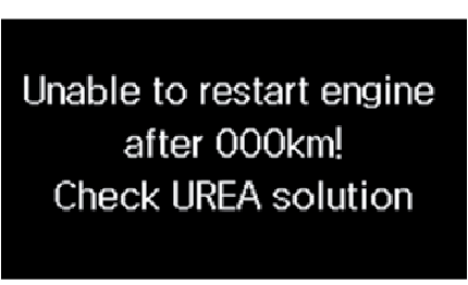 |
- Warning lamp (lit), warning beep (sounds), warning message (dis-played)
- Secondary warning is displayed at drivable distance of 800 km to 0 km after the primary warning due to the faulty DEF system. |
|
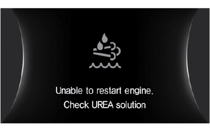 |
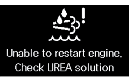 |
- Warning lamp (lit), warning beep (sounds), warning message (dis-played)
- Tertiary warning is displayed at drivable distance of 0 km after the secondary warning due to the faulty DEF system. (impossible
to operate vehicle)
|
|
|
Warnings due to DEF injection system |
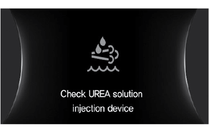 |
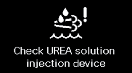 |
- Warning lamp (lit), warning beep (sounds), warning message (dis-played)
- Corresponding first warning is displayed for 50 km of driving when the DEF injection system is faulty. |
|
|
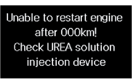 |
- Warning lamp (lit), warning beep (sounds), warning message (dis-played)
- Secondary warning is displayed at 50 km of driving since the first warning occurs due to the DEF injection system. |
|
 |
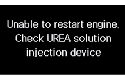 |
- Warning lamp (lit), warning beep (sounds), warning message (dis-played)
- Tertiary warning is displayed at drivable distance of 0 km after the secondary warning due to the DEF injection system.
(impossible to operate vehicle)
|
|
|
Warning due to low quality DEF |
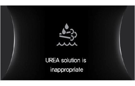 |
 |
- Warning lamp (lit), warning beep (sounds), warning message (dis-played)
- Corresponding first warning is displayed while driving 50 km when low quality DEF is used. |
 |
 |
- Warning lamp (lit), warning beep (sounds), warning message (dis-played)
- Secondary warning is displayed after 50 km of driving since the first warning occurs due to low quality DEF. |
|
|
Warning due to low quality DEF |
 |
 |
- Warning lamp (lit), warning beep (sounds), warning message (dis-played)
- Tertiary warning is displayed at drivable distance of 0 km after the secondary warning due to low quality DEF. (impossible
to operate vehicle)
|
|
Low SCR catalyst purification efficiency |
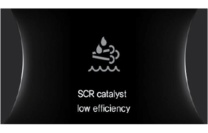 |
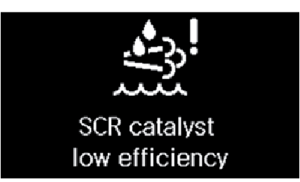 |
- Warning lamp (lit), warning beep (sounds), warning message (dis-played)
- Corresponding first warning is displayed for 50 km of driving when the SCR catalyst purification efficiency is low. |
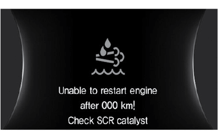 |
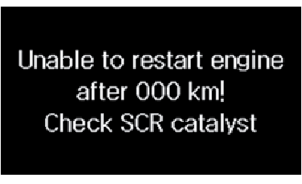 |
- Warning lamp (lit), warning beep (sounds), warning message (dis-played)
- Secondary warning is displayed after 50 km of driving since the first warning occurs due to low SCR catalyst purification
efficiency.
|
|
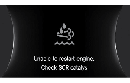 |
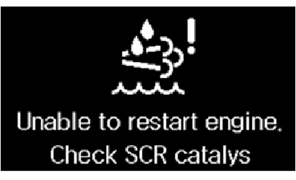 |
- Warning lamp (lit), warning beep (sounds), warning message (dis-played)
- Tertiary warning is displayed at drivable distance of 0 km after the secondary warning due to low SCR catalyst purification
efficiency. (impossible to operate vehicle)
|
8.10.5 Filling DEF
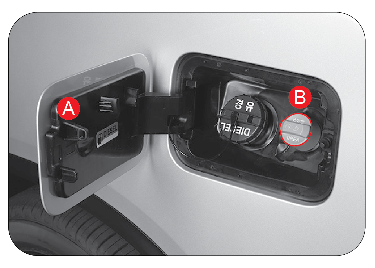
| 1. | Put the gear selector lever to the “P” position. |
| 2. | Always turn off the engine. |
| 3. | Open the fuel filler cover ( A ) with the all doors unlocked. |
| 4. | Turn the DEF filler cap (B ) counterclockwise to open it. |
| 5. | Refill the DEF with the DEF can/bucket |
| 6. | When refilling is completed, turn the DEF filler cap clockwise to close it. |
| 7. | Close the fuel filler cover. |
| • | Fill DEF as required. Maximum Storage capacity 25 litre. Minimum filling 10 liters. |
| • | Make sure that the DEF does not overflow out of the filler hole when filling it. |
| • | Make sure that the DEF does not flow into the fuel filler neck when filling the DEF. Otherwise, the fuel system and other vehicle systems can be affected, resulting in severe damage to the vehicle. |
| • | Make sure that any foreign material does not get into the DEF tank while filling the DEF. |
| • | Use only genuine DEF that meets ISO 22241 standard. Otherwise, the vehicle systems may be damaged seriously and the vehicle may not be operated. |
The DEF may irritate the skin, eyes and respiratory system. If it gets on your body, immediately flush out with plenty of
clean water. Consult a physician, if necessary.
| • | The SCR has a catalyst in it, which can be broken when external force is applied to it. |
| • | Do not arbitrarily modify the exhaust pipe length, direction and structure of the exhaust system. Otherwise, it may cause severe damage to the exhaust gas reduction efficiency or the emission control system. |
| • | The water coming from the exhaust pipe is weak acid, which may cause damage to the skin. Do not allow the water to come in contact with your skin. |
| • | Since the exhaust gas aftertreatment system operates at very high temperature, be sure to cool it down before you work on it and take care not to burn your skin during service. |
| • | Always use only genuine DEF that meets ISO 22241 standard. |
| • | The DEF injection system collects the DEF in the DEF supply line into the DEF tank for several minutes when ignition is turned off. Carry out system inspection or maintenance when DEF collection is completed. |
| • | Use of low quality DEF or DEF containing an unauthorized additive may both aggravate air pollution and cause severe damage to the DEF system and other vehicle systems, which may require you to replace the entire emission control system. |
| • | For safe use, read the user manual thoroughly before using the DEF. |
| • | The DEF is a colorless and odorless aqueous liquid with no flammability and toxicity, but it is classified as a harmful/hazardous substance. Please handle with care. |
| • | The DEF may irritate the skin, eyes and respiratory system. If it gets on your body, immediately flush out with plenty of clean water. Consult a physician, if necessary. |
| • | In case of ingestion, immediately rinse with clean water, drink plenty of water, and be sure to seek medical advice. |
| • | Consult a physician immediately if an allergic reaction occurs. |
| • | Keep the DEF out of the children’s reach. |
| • | If the DEF gets on the surface of the vehicle, etc. while filling it, immediately wash it out with plenty of clean water. If the DEF remains on the surface of the vehicle, it will turn into a white crystal that will eventually contaminate the surface. |
| • | Make sure that the DEF does not flow into the fuel filler neck when filling the DEF. Otherwise, the fuel system and other vehicle systems can be affected, resulting in severe damage to the vehicle. |
| • | Fill the DEF in a shady and well ventilated area. Exposure to direct sunlight may increase ammonia |
| • | Opening the DEF filler cap when the vehicle or ambient temperature is high may release ammonia vapor. Never inhale the leaking ammonia vapor. |
| • | Do not open the DEF filler cap in confined spaces. |
| • | The DEF can be frozen in low temperature (-11°C). When the DEF is frozen, the exact remaining amount of it can not be measured. When the DEF melts through the hot wire after several minutes since the engine is started, check its level. |
| • | Wear protective gloves, protective clothing, and protective goggles when handling DEF. |
It is unlawful to tamper with or remove any component of the after treatment system. It is strongly recommended not to use
DEF which is not meeting above specification. Further, this may lead to emission non compliance and warranty will be void.
| • | Use Genuine DEF MaxiCLEAN always. |
| • | Incase of non availability of above Diesel Exhaust Fluid (DEF) complying to IS17042 (or) ISO22241 specification can be used. |
| • | Never attempt to use agricultural grade urea mixed with water. Agricultural grade urea does not meet the necessary specifications and the after treatment system of your vehicle may be damaged. |
| • | Total DEF quantity inside the DEF Tank should never be more than 25 liters. Overfilling may result in system/component failure. |
| • | DEF quality and purity can be ensured only if it is stored properly. Hence ensure the storage of DEF in cool, dry place between storage. |
| • | Do not add urea to DEF and do not dilute with water. This may cause after treatment system damage. |
| • | While refilling DEF inside tank, be careful not to allow any foreign particles, liquids, wiping paper/clothing fibers or lint to get inside the system. These may clog or damage the system. |
| • | If DEF is spilled over vehicle components and metal surfaces, rinse with wate or wipe off with sponge and water. DEF residues will corrode the components and metal surfaces, painted body panels. |
| • | DEF is not a fuel additive and must not be added to the diesel fuel tank. If DEF is mixed with the diesel fuel, engine /fuel system could get damaged. |
| • | In such a case, do not start the engine and immediately contact nearest Mahindra Authorised Dealer for assistance. |
Contamination/Incorrect DEF
In the event that incorrect or contaminated fluid is filled in side DEF Tank, contact an authorized M&M dealer to determine
the appropriate repair direction.