1 INTRODUCTION AND SAFETY PRECAUTIONS
1.1 Introduction
Dear Customer,
Congratulations on purchasing Mahindra eVERITO. Your vehicle has been designed to provide years of safe and dependable service, as long as it is used and maintained in accordance with the instructions provided in this manual.
All persons who will use and/or maintain this vehicle must read, understand and follow all warnings and instructions provided in this manual. This Owner's Manual should be considered an integral part of the vehicle and should remain with the vehicle. However, nothing in this manual, and none of the safety devices installed in the vehicle, are a substitute for careful operation and common sense. Always make sure that your vehicle is in optimum working order, and take note of the road and weather conditions under which you are using your vehicle.
If you have any questions concerning the proper use or maintenance of your vehicle, please call your Authorized Mahindra Dealer.
We extend our best wishes for safe and pleasurable motoring.
Sincerely,
MAHINDRA & MAHINDRA LTD
1.2 Electric Vehicle System
Electric vehicle operates differently compared to an internal combustion engine vehicles as it is powered by battery power pack. Car battery must be charged with electricity before driving it. As car is driven, stored energy in battery pack gradually decreases and if discharged completely to 0% then will not drive until battery pack is recharged. Charging time varies depending on state of charge in car and ambient conditions. Normal charge time is 9 hours.
An auxiliary 12V battery in car, enables to wake up car in case 'Vacation Mode' is activated in car at idle condition. Battery pack powers drive motor and car is equipped with regenerative electric braking and vacuum assisted hydraulic brakes.
Electric car is an eco-friendly vehicle that does not release any noxious emissions like carbon monoxide, carbon dioxide & nitrogen oxide.
Pay special attention to pedestrians. Because there is no engine noise, pedestrians may not know the vehicle is approaching, moving or about to move, and may step into the path of vehicle travel.
For preventing damage to the Li-ion battery pack:
- Do not expose to very high temperatures for longer duration.
- Do not use car battery for any other purpose, consult your dealer or manufacturer for help.
Make sure that the service disconnect switch is in pressed position when performing any part replacement or repairs.
The EV (Electric Vehicle) system uses a high voltage current. Failure to follow the proper handling instructions may cause serious injury or death.
An EV (Electric Vehicle) cannot be push started or tow-started. Attempting to do so may cause traction motor damage.
The EV (Electric Vehicle) system uses high voltage up to approximately DC 72 volt. The system can be hot during and after starting and when the vehicle is shut off. Be careful of both the high voltage and the high temperature. Obey the labels that are attached to the vehicle.
Never disassemble, remove or replace high-voltage parts and cables as well as their connectors. High voltage cables are colored orange.
Disassembling, removing or replacing those parts or cables can cause severe burns or electric shock that may result in serious injury or death. The vehicle high voltage system has no user serviceable parts. Take your vehicle to the Mahindra certified dealer for any necessary maintenance.
If you must work with the EV (Electric vehicle) system is turned on, keep hands, clothing, hair and tools away from moving fans and any other moving parts.
Keep smoking materials, flames and sparks away from the 12- volt and HV batteries.
Always check available energy for your required travel distance by checking 'state of charge' and also 'distance to empty'. Whenever charge level goes below 15%, the SOC bar starts blinking giving an indication to user to drive carefully to reach destination. If charge level drops below 10%, car will drive in 'POWER SAVE MODE' reducing car performance and automatically turns off air- conditioning.
Battery pack will get discharged when it is parked idle for long time. Hence activate 'Vacation Mode' via mobile application (if equipped) to optimize charge level and avoid deep discharge.
Vehicle uses a 72 volts battery system. Some of systems could be hot before & after their usage. Hence pay attention and follow warning labels located at places in vehicle. Never try to access, remove parts / cables / connectors which can cause shock or severe burns or result in serious injury. 72 voltage cables are colour coded in Orange & systems are not user serviceable. For any maintenance, contact your authorized service center.
- Make sure to turn off drive system before leaving vehicle.
- Engage parking brake prior to getting out of the vehicle.
- Do not allow untrained person to access EV system and apprise immediate responders in any events that this is an electric vehicle.
- Vehicle will not run with completely discharged battery. At low SOC avoid repeated acceleration resulting in more energy consumption that can be avoided by gradual acceleration and maintaining steady speed.
- Driving in down gradient, when accelerator pedal is released, regenerative brakes will provide some energy to recharge battery pack and simultaneously assists in deceleration of vehicle assisting in vehicle control.
- Brake should be applied to slow down or stop vehicle in drive.
- You may hear some sound and feel vibration in drive that are normal;
- Drive motor makes small sound during its operation, also will be higher in deceleration of vehicle.
- Brake vacuum pump makes sound during braking operation.
- Contactor makes sound when vehicle is switched on and authentication.
- In AC cooling, motor and condenser fan comes on during operation.
- In event of battery temperature is below 0°C or less, battery pack will not accept charge, hence park your car at warm climatic condition.
- In event of battery temperature is below -5°C, car will not drive, hence park at warm location.
- Performance of battery will decrease with time and usage. This does not indicate any defect in battery pack.
- Battery pack has limited life and when its charge holding capacity reaches below specific level, it may require an inspection from service persons and may need battery pack replacement.
- It is recommended and mandatory that during process of battery or vehicle / components disposal, owner should contact authorised dealer for guidance and information on recycling or proper disposal without causing any environmental pollution.
- During drive as the charge level drops below 20%, car will drive in 'E' (ECONOMY) mode limiting drive power. Further if charge level drops below 10%, car will drive in 'L' (LIMP HOME) mode with POWER SAVE MODE message on cluster. If heater or AC is ON, will get turned off.
- Driving in 'B' mode with high acceleration will result in more power consumption reducing your drive range
In event of accident:
- If your vehicle is drivable, pull your vehicle off the road, shift to Neutral (N), apply the parking brake and turn the EV (Electric Vehicle) system off.
- Check your vehicle to see if there are exposed high-voltage parts or cables. To avoid personal injury, never touch high- voltage wiring, connectors, and other high-voltage parts, such as E-BOX and B-BOX. An electric shock may occur if exposed electric wires are visible when viewed from inside or outside of your vehicle. Therefore, never touch ex-posed electric wires.
- If the vehicle receives a strong impact to the floor while driving, stop the vehicle in a safe location and check the floor. Leaks or damage to the Li-ion battery may result in a fire. If you discover them, contact emergency services immediately. Since the fluid leak may be lithium manganate from the Li-ion battery, never touch the fluid leak inside or outside the vehicle. If the fluid contacts your skin or eyes, wash it off immediately with a large amount of water and receive immediate medical attention to help avoid serious in-jury.
- If a fire occurs in the EV (Electric Vehicle), leave the vehicle as soon as possible. Only use a type ABC, BC or C fire extinguisher that is meant for use on electrical fires. Using water or the incorrect fire extinguisher can result in serious injury or death from electrical shock.
- If your vehicle needs to be towed, do it with the front wheels raised. If the front wheels are on the ground when towing, the traction motor may generate electricity. This may damage the components of the EV (Electric Vehicle) system and cause a fire.
- In the event of an accident that requires body repair and painting, the vehicle should be delivered to a Mahindra certified dealer to have the Li-ion battery pack and high voltage parts such as the B-BOX, E-BOX, including the wiring harness, removed prior to painting. Li-ion battery packs exposed to heat in the paint booth will experience capacity loss. Damaged Li-ion battery packs may also pose safety risks to untrained mechanics and repair personnel.
If vehicle cannot be assessed for extent of damage, do not touch vehicle and contact nearest Authorized service center or customer care executive for support.
Don't carry out any welding work on vehicle outside Mahindra certified dealer.
1.3 Additional Safety Features
- Car does not move unless charge cable is unplugged from charge port.
- In case you have forgotten to engage parking brake after turning off key switch & door is opened, warning chime gets activated.
- Depending on level of charge, your car is designed to automatically switch to "Economy mode" or "power save mode" to reach nearby location.
- Vehicle should be driven < 20 kmph speed on speed breakers and rough roads to avoid damage to the battery box under the vehicle.
- Tyres used in car are tubeless, designed for all weather conditions. They provide best driving range with improved road grip.
- Isolation check: Vehicle will run isolation check automatically in below 3 conditions. If fault occurs vehicle will shut down.
- Initial isolation check is done before charging when vehicle is plugged in for charging. If isolation fault occurs vehicle will shut down.
- During drive mode, if Isolation fault occurs vehicle can be driven in safe mode as long as key is not turned off. Once the key is turned off vehicle will shut down.
- During idle condition isolation detection is done every 8 hrs. If isolation fault occurs vehicle will shut down.
In case of vehicle shutdown contact Authorized Mahindra Dealership.
1.4 Cooling and AC
Cooling/Heating will be turned off (including blower) when SOC drops below 10%
1.5 End Of Life - Disposal
As this is an electric vehicle, many electric and electronic parts are used in its system. Part composition is given in next column that can be recycled after the end of life of car & it has to be disposed without causing pollution to environment
Your vehicle contains a sealed Li-ion high voltage battery. If the Li-ion battery is disposed improperly, there is a risk of severe burns and electrical shock that may result in serious injury or death and there is also a risk of environmental damage.
Composition
Vehicle is made from steel, Aluminium, Lead, copper, wood, other plastics, glass, rubber & misc. These are reusable by recycling & also some are hazardous to environment and living beings hence to be disposed as per local pollution board regulations.
Disposal
- As batteries are made of lithium & iron phosphate with solvents as electrolyte which are harmful, make impact on environment are to be disposed as per local pollution board regulations.
- Similarly ABS & other plastic panels, materials used are to be disposed to accredited agencies for recycling.
- Most of other materials are reusable, hence components are to be segregated as per their composition as hazardous and non- hazardous, disposed to accredited recycling agencies. Hence it is advised to contact authorized service centre.
The vehicle has sealed Li-ion battery pack. Improper disposal of battery could lead to risk of severe burns and electrical shock that may result in serious injury or death and also may cause damage to environment.
1.6 Safety Symbols
Carefully read, understand and follow the safety symbols/ instructions given in this manual.
Legend of the Symbols
To emphasize information and procedures regarding safety, use, maintenance, etc., the following symbols are used throughout the manual.
DANGER indicates an imminently hazardous situation which, if not avoided, will result in death or serious injury.
WARNING indicates a potentially hazardous situation which, if not avoided, could result in death or serious injury.
CAUTION indicates a potentially hazardous situation which, if not avoided, may result in minor or moderate injury and/or property damage.
NOTICE indicates important information relevant to the vehicle, the vehicle's use or to sections of this manual to which particular attention must be paid for optimum use of the vehicle.
If you see this symbol, it indicates "no", "do not," "do not do this," or "never".

1.7 General Safety Information and Instructions
Failure to follow the warnings and instructions provided in this manual could result in failure of the vehicle, an accident and/or serious personal injury.
- Carefully read, understand and follow the warnings and instructions given in this manual. This manual is an essential part of the product. Keep it in the vehicle glove box for future reference
- Please note that throughout this manual, reference is made that "an accident" could occur. An accident could cause you or a bystander to sustain severe personal injury, or result in property damage
- Never use a mobile phone or personal music device while driving. This may take your focus off the road and lead to accidents
- Please be advised that many service and repair tasks require specialized knowledge, tools and experience. General mechanical aptitude may not be sufficient to properly service or repair your vehicle. If you have any doubt whatsoever regarding your ability to properly service or repair your vehicle, please contact your Authorized Mahindra Dealer or a qualified technician
- Inspect the seat belt system periodically, checking for cuts, frays or wear in the seat belt webbing, or loose buckles,retractors, anchors or other loose parts. Damaged parts must be replaced immediately
- Examine tires for excessive tread wear and uneven wear patterns. Check for stones, nails, glass, or other objects lodged in the tread and check sidewalls for any cuts, cracks, or other signs of wear. Replace as necessary
- Always maintain the safety labels affixed to your vehicle in a good legible condition
- All signal lamps, buzzers, shields, guards and other protective safety devices must always remain in place and in good, proper working condition
- The life span of Mahindra products depend on many factors. Improper use, abuse or harsh use in general may compromise the integrity of the vehicle and significantly reduce its life span. The vehicle is also subject to wear over a period of time. Please have your vehicle regularly inspected by an Authorized Mahindra Dealer or a qualified mechanic. If the inspection reveals any damage or excessive wear, immediately replace or have the component serviced
- We recommend that you use only genuine parts supplied by Mahindra. The use of non-Mahindra parts will not be covered by warranty
- Never crawl under or be in close proximity to the vehicle when it is lifted off the ground (by a jack), unless the vehicle is properly supported with jack stands, wheel chocks and other appropriate safety devices
- Never attempt any repairs or adjustments to any component while the vehicle is in motion.
- The vehicle identification plates are the only legal identification reference, hence it is necessary to keep them in good condition. Never modify data on the plates or remove them. The customer is responsible for any possible tampering with the plates, which will immediately void the warranty
1.8 To Owners of a Mahindra Vehicle
Driving and Alcohol
Your driving ability can be seriously impaired by alcohol even if the blood alcohol level is far below the legal minimum. Drunken driving is one of the most frequent causes of accidents.
Never drink and drive. Drinking and driving will lead to an accident resulting in serious personal injury.
Driving and Drugs/Medication
Your driving ability can be seriously impaired through the use of prescription or non-prescription drugs or medication (even cough syrup). If you are taking any sort of drug or medication, be sure that it will not affect your driving ability.
Mobile Phones Warning
Use of electrical devices such as mobile phones, computers, portable radios or other by the driver while driving is dangerous. If use of a mobile phone is necessary despite this warning, use a hands free system to at least leave the hands free to drive the vehicle. Please comply with the legal regulations concerning the use of communication equipment in vehicles in your country.
Servicing
If you have any questions concerning the proper use or maintenance of your vehicle, please call your Authorized Mahindra Dealer.
Mahindra Genuine Parts
Mahindra uses high quality parts for building vehicles. In the event that any parts need replacement, we recommend that you use only Mahindra genuine parts.
Non-Mahindra parts may harm vehicle performance and will not be covered by your Mahindra warranty. To avoid counterfeit parts and to protect our brand image, Mahindra genuine parts are packed in a branded carton. Look for the "Mahindra Genuine Parts" logo.
Any unauthorized modifications or alterations to this vehicle or failure to use appropriate specification and quality spare parts could seriously affect vehicle road worthiness and safety leading to an accident, resulting in serious injury
Vehicle Safety
When leaving your vehicle unoccupied;
- Always remove the ignition key when you park the vehicle
- Close all the windows completely and lock all the doors
- Engage the park brake.
- Do not leave any valuables in your vehicle. If you must leave something in your vehicle, hide them and securely lock all the doors
2 GENERAL
2.1 Dimensions
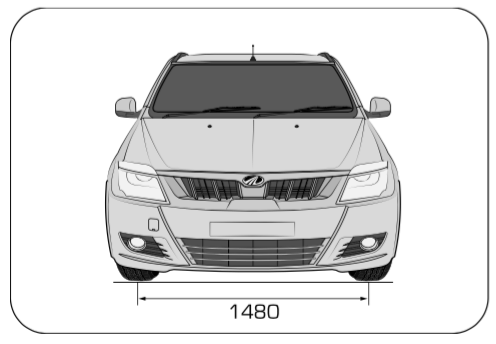
2.1.1 Front View
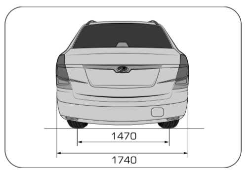
2.1.2 Rear View
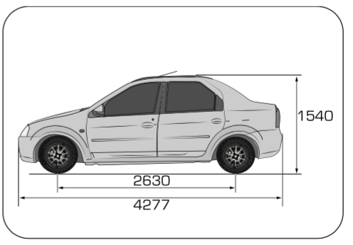
2.1.3 Side View
| DIMENSION & WEIGHTS | mm |
|---|---|
| Wheel Base | 2630 mm |
| Overall Length | 4277 mm |
| Overall Width | 1740 mm |
| Overall Height | 1540 mm |
| Ground Clearance | 128 mm (Laden) / 172 mm (Unladen) |
| Track Width (Front & Rear) | 1480 (Front), 1470 (Rear) |
2.2 Bulb Specification
| Lamp Bulb | Wattage | No. of Bulbs per Vehicle |
|---|---|---|
| Head Lamp - Low Beam | 12H4 | 2 |
| Head Lamp - High Beam | 12H4 | 2 |
| Parking Lamps (Front) | 12W5W | 2 |
| Turn Signal Lamp (Front) | 12WY21W | 2 |
| Fog Lamp (Front) * | 12H11-55W | 2 |
| Stop Lamp | 12W16W | 2 |
| Turn Signal Lamp (Rear) | 12W16W | 2 |
| Reverse Lamp | 12W16W | 2 |
| Parking Lamps (Rear) | 12W5W | 2 |
| Side Marker Lamp (Rear) | 12W5W | 2 |
| High Mount Stop Lamp | 12P21W | 1 |
| Number Plate Lamp | 12W5W | 2 |
| * if equipped | ||
2.3 Fuses & Relays
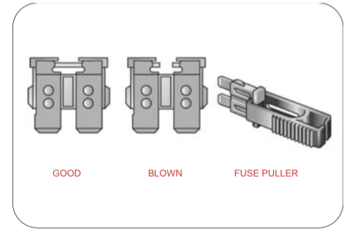
A fuse is the most common electric protection device. A fuse is placed in an electrical circuit, so that when current flow exceeds the rating of the fuse it blows off.
The element in the fuse melts, opening the circuit and preventing other components of the circuit from being damaged by the over current. The size of the metal fuse element determines the rating. Once a fuse blows off, it must be replaced with a new one.
Switch the ignition and all electrical equipment OFF before touching or attempting to change a fuse.
Fit replacement fuse with the same rating as the one you have removed.
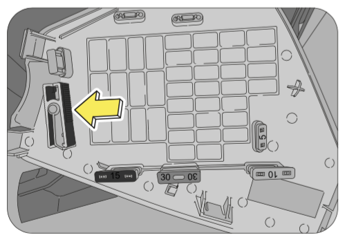
You can identify a blown fuse by a break in the filament. All fuses except high current fuses are a push fit. A fuse puller should be used to remove the fuse from its position.
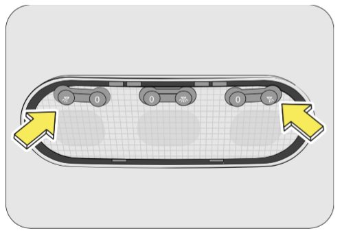
Fuse Locations
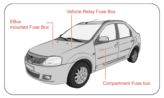
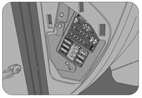
Passenger Compartment Fuse Box
Fully open the co-driver door and slide the seat backwards. The main central fuse box is located on the left side of the instrument panel. Price out the securing cover to access the fuse box.
Never touch fuses with bare hands. Always use fuse puller located in instrument panel fuse box cover to remove and refit the fuses.
Graphical Fuse Chart
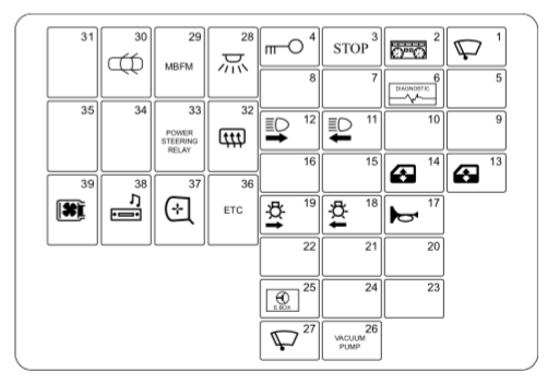
Link the fuse number mentioned in the above chart with the below table to identify the fuse rating for a particular system.
| Fuse | Rating(A) | Description |
| F1 | 20 | Windscreen Wiper Motor - Screen Wash/Wipe Combination Switch |
| F2 | 5 | Instrument Panel – Ignition Power Relay |
| F3 | 15 | Brake Lamp Switch |
| F4 | 5 | Immobilizer Battery |
| F5 | NOT USED | |
| F6 | 10 | Diagnostic |
| F7 | NOT USED | |
| F8 | NOT USED | |
| F9 | NOT USED | |
| F10 | NOT USED | |
| F11 | 10 | Left-Hand Headlight - Instrument Panel Display |
| F12 | 10 | Right-Hand Headlight |
| F13 | 30 | Rear Right-Hand Electric Window Control - Rear Left-Hand Electric Window Control |
| F14 | 30 | Driver's Electric Window Control |
| F15 | NOT USED | |
| F16 | NOT USED | |
| F17 | 15 | Electromagnetic Horn |
| F18 | 10 | Left Turn |
| F19 | 10 | Right Turn |
| F20 | NOT USED | |
| F21 | NOT USED | |
| F22 | NOT USED | |
| F23 | NOT USED | |
| F24 | 10 | Fog lamp Relay * |
| F25 | 5 | EBox Ignition Supply |
| F26 | 15 | Electric Vacuum Pump |
| F27 | 10 | Washer |
| F28 | 10 | Consumer Cut-Out - Instrument Panel – Radio – Body Control - Luggage Compartment Light |
| F29 | 15 | Mahindra Body Control Unit |
| F30 | 30 | Mahindra Body Control Unit |
| F31 | 15 | |
| F32 | 30 | Heated Rear Screen Control |
| F33 | 10 | Power Steering Relay |
| F34 | NOT USED | |
| F35 | NOT USED | |
| F36 | 30 | Cold Air Blower Unit |
| F37 | 5 | Outside Rear View Mirror |
| F38 | 10 | Radio - First Row Power Socket |
| F39 | 30 | Cold Air Blower Unit |
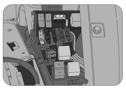
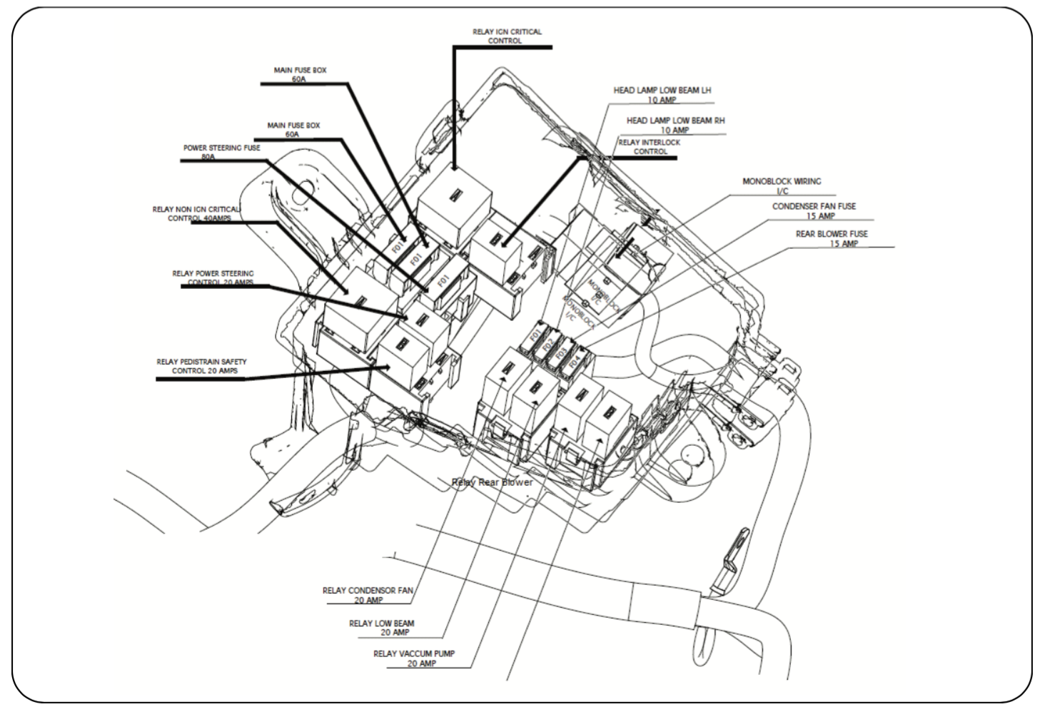
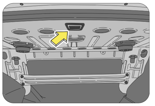
EBox Compartment Fuse Box
EBox compartment fuse box is located adjacent to vehicle auxiliary battery. Remove the fuse box cover by pressing the clips from both sides.
2.4 Flat Tire
In case of a flat tyre during driving, reduce your speed gradually, keeping a straight line. Move cautiously off the road to a safe place well away from traffic. Park on a level spot with firm ground. Stop the vehicle and turn ON your hazard warning flashers.
Firmly apply the parking brake. Have everyone come out of the vehicle on the side away from traffic.
Never stop your vehicle in a traffic lane to change a tire. You could be hit by an oncoming vehicle. Keep driving until you reach a safe location.
Lifting a vehicle to change a tire or perform maintenance is very dangerous if you do not have the requisite tools, safety equipment and training. The jack provided along with the vehicle is to be used only for changing a spare tire. It is never to be used to perform any other maintenance or repair on the vehicle.
Never place any part of your body under any portion of the vehicle when it is supported only by the jack. You could be crushed by the vehicle if it falls off a jack. Keep by-standers away from the vehicle.
Find level, solid ground that is clear of oncoming traffic. If you cannot find a safe place to stop, it is better to drive on a flat tire and damage the rim than it is to risk being hit by oncoming traffic.
The following sections outline the procedure for changing a flat tire;
2.4.1 Tool Kit
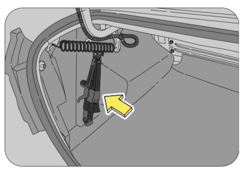
The jack is located in the boot to the left held in place by a velcro strip. The jack extension is also attached to the jack.
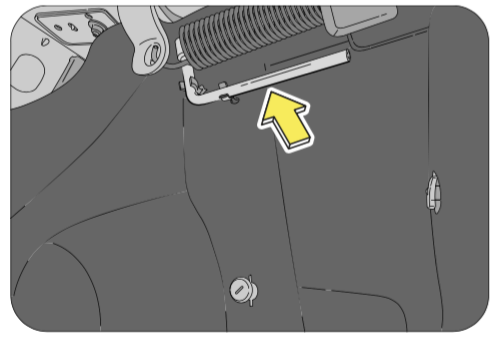
The wheel brace (spanner) is located in the boot to the right held in place by snap fitting clips.
The warning triangle is in a pouch in the boot.
2.4.2 Spare Wheel Removal
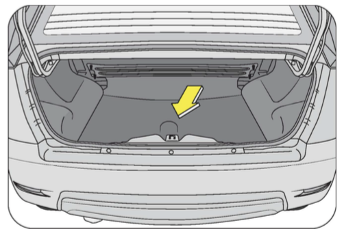
Spare wheel is located under the boot floor at the rear end of the vehicle. It is held in place by a winch nut underneath the luggage compartment floor carpet.
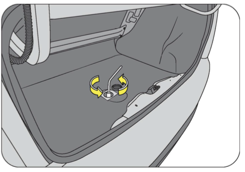
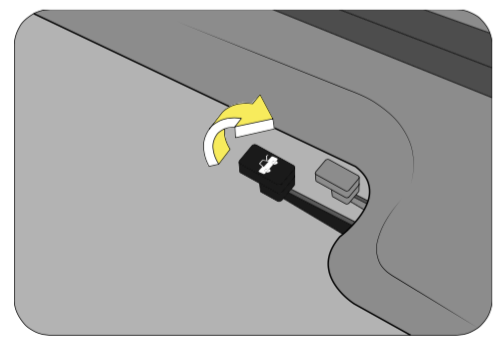
- Lift the carpet and remove the plug cover
- Rotate the securing winch nut anti-clockwise using the wheel spanner to lower the spare wheel.
- Remove the securing spare wheel hub bracket from the spare wheel.
- Pull the spare wheel from under the vehicle.
Snap-fit Wheel Cover Removal (if equipped)
Wrap the tip of a screw driver with cloth, insert it near the lugs of the wheel cover and pry the cover away from the wheel.
Do not try to pry off the wheel cover by hand alone. Take due care in handling the wheel cover to avoid unexpected personal injury.
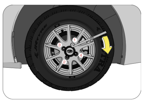
2.4.3 Wheel Nut Loosening
Always loosen the wheel nuts before raising the vehicle. Turn the wheel nuts counter clockwise to loosen. To get maximum leverage, fit the spanner to the nut so that the handle is on the left side. Grab the spanner near the end of the handle and push down on the handle. Be careful that the spanner does not slip off the nut. Do not remove the nuts, but loosen them by one or two turns.
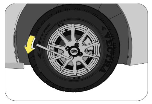
Do not apply force with your legs (or stand) on the wheel spanner while tightening the wheel nuts.
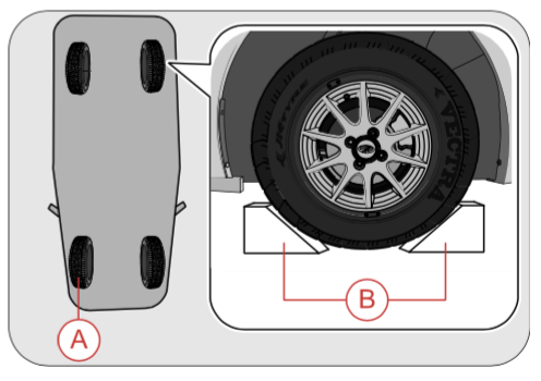
| 1 | Flat Tyre | 2 | Chock Blocks |
Block the wheel diagonally opposite the flat tyre to keep the vehicle from rolling when it is jacked up. When blocking the wheel, place a wheel block in front of one of the front wheels or behind one of the rear wheels.
2.5 Jacking
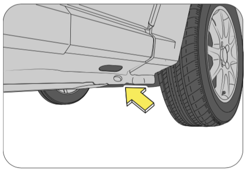
Locate the jack points in the front or rear as needed. They can be identified by a slot along the skirt on both sides of the vehicle which is used to fit the jack precisely.
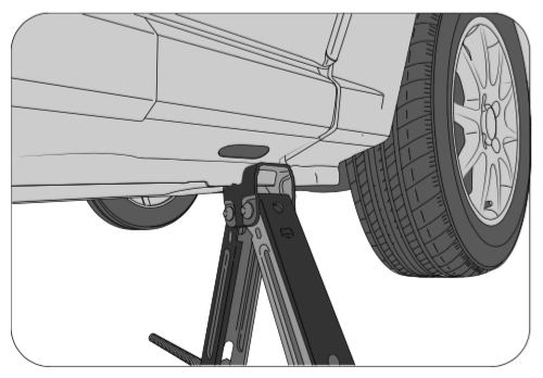
Position the jack at the correct jacking point. Make sure the jack is positioned on a level and solid place. Ensure no one is in the vehicle.
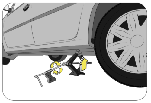
To raise the vehicle, insert the jack handle end along with the extension into the jack and turn it clockwise with the jack handle. As the jack touches the vehicle and begins to lift, check that it is properly positioned. Raise it high enough so that the spare tire can be installed. Remember you will need more ground clearance when putting on the spare tire than when removing the flat tire.
Make sure to set the jack properly in the jacking point. Raising the vehicle with improperly positioned jack will damage the underbody of vehicle or may allow the vehicle to fall off the jack and cause personal injury.
- Use the jack only for lifting your vehicle during wheel changing
- Do not raise the jack with someone in the vehicle
- When raising the vehicle, do not place any objects on top of or underneath the jack
- Raise the vehicle only high enough to remove and change the wheel
- Follow jacking instructions
- Do not start the vehicle while it is supported by the jack
Never get under the vehicle when the vehicle is supported by the jack alone.
Remove the wheel nuts. Lift the flat tire straight off and place it aside. Roll the spare wheel into position and align the holes in the wheel with the bolts. Lift up the wheel and get at least the top bolt started through its hole. Wiggle the wheel and press it back over the other bolts.
Before putting on the wheels, remove any corrosion on the mounting surfaces with a wire brush or such. Installation of wheels without good metal to metal contact at the mounting surface can cause wheel nuts to loosen and eventually cause a wheel to come off while driving.
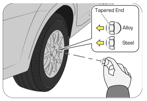
Reinstall the wheel nuts with the tapered end inward and tighten by hand. Press the wheel inward and tighten the wheel nuts further.
Never use oil or grease on the bolts or nuts. Doing so may lead to over tightening the nuts, wheel nut spanner slip, damage the bolts and also may cause personal injuries. Also, nuts may loosen and the wheels may fall off, which could cause a serious accident. If there is oil or grease on any bolt or nut, clean before installing wheel nuts.
Lower the vehicle completely and tighten the wheel nuts using the wheel nut spanner. Turn the jack extension counter clockwise using the wheel nut spanner to lower the vehicle, making sure the handle remains firmly fit onto the jack handle extension. Do not use other tools or any additional leverage other than your hands, such as a hammer, pipe or your foot. Make sure the spanner is securely engaged over the nut. Tighten each nut a little at a time in the diagonally opposite order. Repeat the process until all the nuts are tight.
Improperly or loosely tightened wheel nuts are dangerous. The wheel could wobble or come off. This could result in loss of vehicle control and cause a serious accident. Always make sure all the wheel nuts are properly/securely tightened to the specified torque.
If you have rotated , repaired , changed your tires or changed the wheel rims, check the wheel nuts are still tight (to the reqd. torque) after driving about 1000 Kms.
Re-install the Snap-fit Wheel Cover (if equipped)
Put the wheel cover into position aligning the nozzle on the wheel to the nozzle clearance on the wheel cover. Tap it firmly on the sides with your hand to snap it into place.
Restore the tools (jack, wheel spanner, etc.,) in their storage locations.
Align the spare wheel to the centre hub of the wheel well. Firmly tighten the securing plug and put the floor carpet back.
Double check to ensure the tyre is snug against the rear floor of the vehicle.
Check the air pressure on the spare tire and inflate/adjust if necessary. Have the flat tire repaired at the earliest and replace the same with the spare tire.
It is recommended to fix the flat tire at the nearest tire shop and swap the spare wheel back. The wheel balance and alignment differ from wheel to wheel. This may lead to steering and braking issues.
2.6 Technical Specifications
| Technical Specifications | |
|---|---|
| MOTOR | |
| Type | Pure Electric |
| Installation | Transverse Electric power train FWD |
| Max. Output (kW @ rpm) | 31kW / 3000 |
| Max. Torque (Nm @ rpm) | 91Nm/ 1500 |
| TRANSMISSION | |
| No. of Gears | 1 Forward, 1 Reverse |
| Gear Ratio | 10.83 |
| WHEELS & TIRES | |
| Rim | 5.5J x 14" |
| Tires | 185/70 R14 tubeless (Low rolling resistance Tires) |
| Laden Tyre Pressure (front & rear), (kg/ cm2) | Front - 2.4 Kg/cm2 ; Rear - 2.4 kg/cm2 |
| STEERING | |
| Type/Description | Power Assisted - Hydraulic |
| Turning Radius | 5.25 m |
| SUSPENSION | |
| Front | Independent McPherson Strut |
| Rear | H Section Torsion Beam with Shock Absorber |
| Anti Roll Bar | Torsion Type (Only at Front) |
| Shock Absorbers | Telescopic Double Acting & Hydraulic Type |
| BRAKES | |
| Service Brake | Cross Over Hydraulic Type, Assisted by Vacuum Booster with Load Sensing Valve Acting on Rear Wheel |
| Front | Disc |
| Rear | Drum |
| Parking Brake | Mechanical Hand Operated acting on Rear Wheels |
| ELECTRICAL SYSTEM | |
| Battery | TS-200Ahr |
| Drivetrain | 72V |
| PERFORMANCE | |
| Max Speed Kmph – (GVW) | 86 Km/hr (+/- 2 Km) |
| Range (MIDC) -Kerb + D | 110 Km |
| Normal Charge (AC charging 230 V, 15 A): Time (SOC – 0 to 100%) @ ambient (0 oC to 35 oC) |
9 hrs |
| Fast Charge Time @ (15 oC to 35 oC) ambient and battery temperature |
2 hrs +/– 15 mins |
| Acceleration | 0 – 40 (Kerb + D) : 5.7 Sec (+/-0.5 Sec) |
| 0 – 60 (Kerb + D) : 11 Sec (+/-0.5 Sec) | |
| Max. Gradeability | 9 deg |
| Flooding – Water wading | 12” from road |
| VEHICLE | |
| Kerb Weight | 1270 kg |
| GVW | 1700 kg |
3 VEHICLE OVERVIEW
3.1 Front and Side Overview
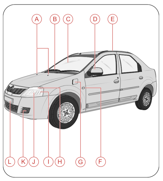
| A | Windshield Washer Jets |
| B | Windshield Wiper |
| C | Front Windshield |
| D | Outside Rear View Mirror (ORVM) |
| E | Ski Rail |
| F | Side Repeater Lamp |
| G | Fast Charging Port |
| H | Front Turn Signal Lamp |
| I | Parking Lamp |
| J | Head Lamp |
| K | Front Fog Lamp (if equipped) |
| L | Front License Plate |
3.2 Rear Overview
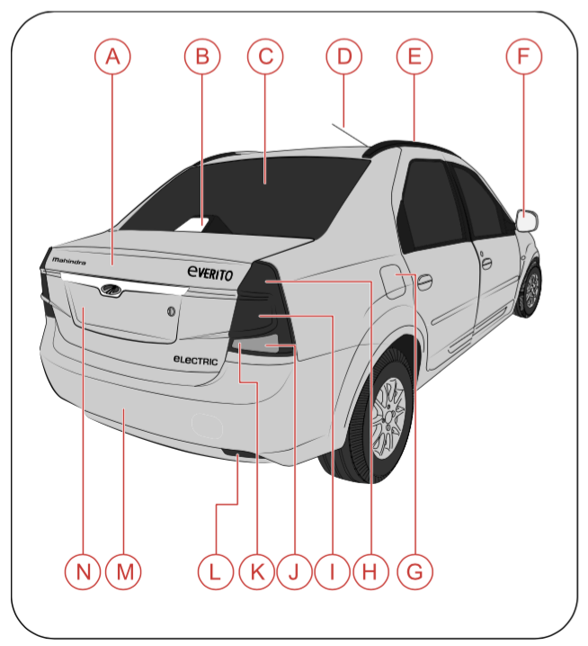
| A | Boot |
| B | High Mounted Stop Lamp |
| C | Rear Windshield |
| D | Antenna |
| E | Ski Rail |
| F | Outside Rear View Mirror (ORVM) |
| G | Normal Charging Port |
| H | Rear Brake Lamp |
| I | Rear Parking Lamp |
| J | Rear Turn Signal Lamp |
| K | Reversing Lamp |
| L | Bumper Reflectors |
| M | Rear Bumper |
| N | Rear License Plate |
3.2 Instrument Panel Overview
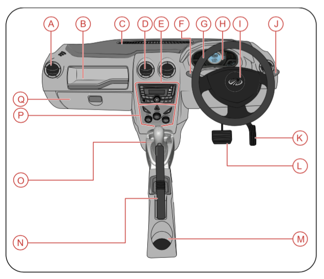
| A | Side Vents |
| B | Upper Storage Area |
| C | Windshield Defrost Vents |
| D | Centre Vents |
| E | Audio System (If equipped) |
| F | Light Combination Stalk |
| G | Steering Wheel |
| H | Instrument Cluster |
| I | Horn Pad |
| J | Wiper Stalk |
| K | Accelerator Pedal |
| L | Brake Pedal |
| M | Cup/Bottle Holder |
| N | Parking Brake |
| O | PRNDL |
| P | HVAC Controls |
| Q | Glove Box |
4 INSTRUMENT CLUSTER OVERVIEW
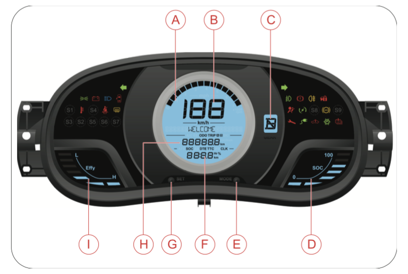
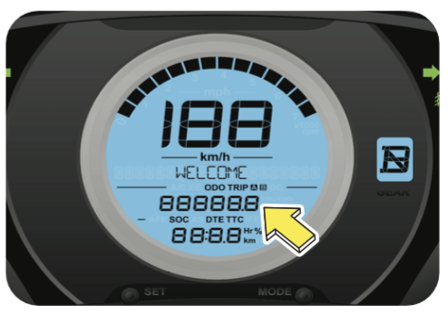
4.1 Instrument Cluster
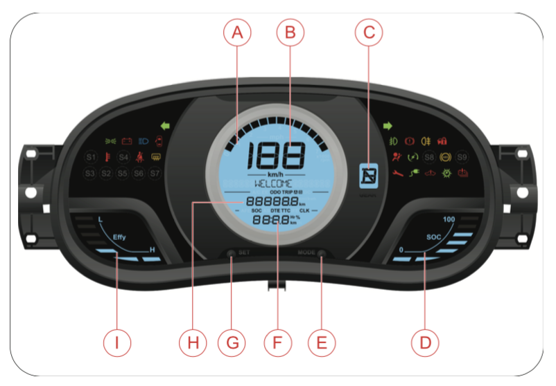
| A | Speedo Segment | F | DTE/SOC/CLK |
| B | Digital Speedometer | G | Set Button |
| C | Gear Indicator | H | Trip meter/ Odometer |
| D | State-of-Charge (SOC) | I | Efficiency Gauge |
| E | Mode Button |
4.2 Warning Lamps Overview
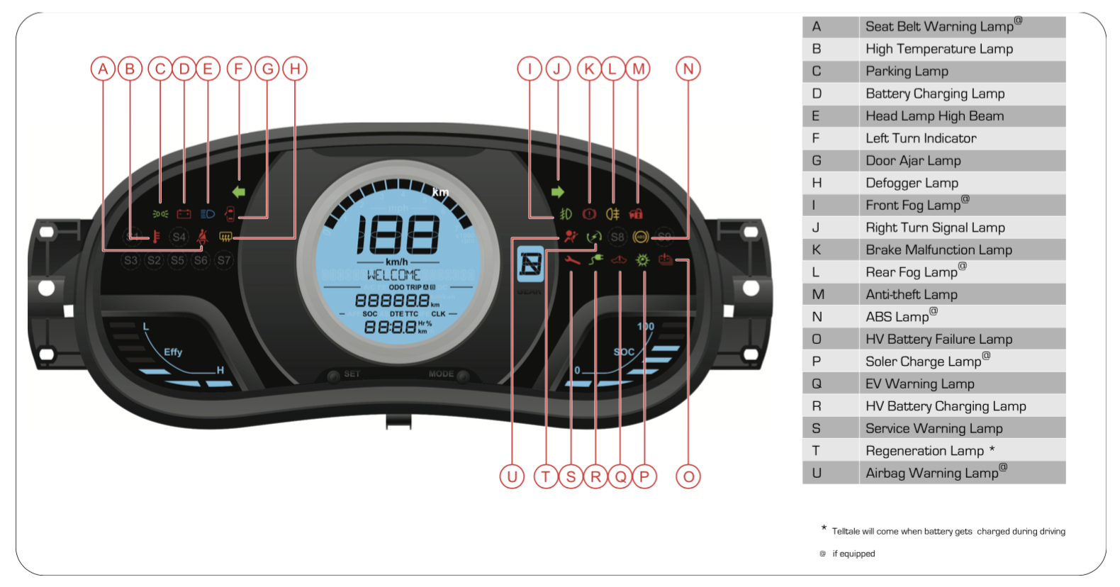
| A | Seat Belt Warning Lamp@ | L | Rear Fog Lamp@ |
| B | High Temperature Lamp | M | Anti-theft Lamp |
| C | Parking Lamp | N | ABS Lamp@ |
| D | Battery Charging Lamp | O | HV Battery Failure Lamp |
| E | Head Lamp High Beam | P | Soler Charge Lamp@ |
| F | Left Turn Indicator | Q | EV Warning Lamp |
| G | Door Ajar Lamp | R | HV Battery Charging Lamp |
| H | Defogger Lamp | S | Service Warning Lamp |
| I | Front Fog Lamp@ | T | Regeneration Lamp * |
| J | Right Turn Signal Lamp | U | Airbag Warning Lamp@ |
| K | Brake Malfunction Lamp |
5 SEATS AND SEAT BELTS
5.1 Driver Seat
5.1.1 Sitting in Correct Position
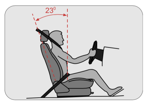
Follow the tips below for a comfortable and safe journey;
- Sit in an upright position with the base of your spine pressed against the seat back
- The driver and front passenger seat head restraint has 5 positions. Adjust it as close as possible to the above specified position, with the top of the head restraint even with the top of your head
- Maintain sufficient distance between yourself and the steering wheel. Maintain at least a ten inch (10") distance from the centre of the steering wheel to your chest
- The top curve of the steering wheel should align with your chin for ideal road visibility
- Adjust your seat and seat back angle such that your wrists rest on the steering wheel
- Ensure your legs are in bent position while fully depressing the accelerator pedal
The seat should be adjusted while still maintaining control of the foot pedals, steering wheel and your view of the instrument panel controls.
Never adjust the driver's seat while the vehicle is in motion. The seat may unexpectedly move and cause the driver to unintentionally operate the accelerator or brake, or turn the steering wheel, causing loss of control of the vehicle, an accident or serious personal injury. Adjust the driver's seat only when the vehicle is not in motion.
Never put objects under the seats. They may interfere with the seat-lock mechanism or unexpectedly activate the seat position adjusting lever, causing the seat to suddenly move, resulting in loss of control of the vehicle, an accident or serious personal injury.
While adjusting the seat, do not put your hands under the seat or near the moving parts. This may lead to injuries.
5.1.2 Front Seat Slide
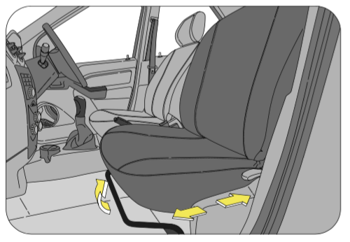
Move the seat forward or backward by lifting the adjustment lever located under the seat front and release once the desired position is reached.
While adjusting the seat, make sure the latch engages fully and the seat is locked firmly in the desired position. An unlocked seat may move in a sudden stop or collision, causing injury to the person in that seat. Push and pull on the seat to be sure it is locked.
5.1.3 Front Seat Recline
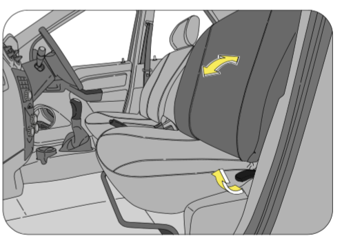
To adjust the seat back, lift the lever located on the outboard side of the seat, lean back, and release the lever at the desired position. To return the seat back, lift the lever, lean forward, and release the lever.
The seat belts provide maximum protection in a frontal or rear collision when the occupants are sitting up straight and well back in the seats. If you are reclined, the lap belt may slide past your hips and apply restraint forces directly to the abdomen, or the shoulder strap may contact your neck. The more the seat is reclined, the greater the risk of serious injury.
When returning the rear-reclined seat back to its upright position, make sure you support seat back while operating the lever.
5.2 Head Restraint
5.2.1 Adjustable Head Restraint
The head restraint comprises of the padded portion which contacts your head and is inserted/locked in receptacles on the top of the seat back.
Your vehicle seats are equipped with head restraints which are vertically adjustable. The purpose of these head restraints is to help limit head motion in the event of rear collision.
Always align top of the head restraint with the top of your head or as close to it as possible. To raise the head restraint, press the lock knob and pull the restraint up. To lower the head restraint, press the lock knob and push the head restraint down.
5.2.2 Removing Seat Head Restraint
The head restraint can be pulled out completely by depressing the locking button while pulling the restraint out.
5.2.3 Installing Seat Head Restraint
Align the head restraint shafts over the holes on the seat top and push the restraint straight down till you hear the lock click.
Keep the seat back as upright as possible so the headrest is behind, not beneath, and almost touching your head.
Never drive with the head restraints not properly adjusted, head restraints removed or inserted in a flipped condition. With no support behind your head, your neck could be seriously injured in a collision.
Head restraints are provided for the front row and second row outboard occupants.
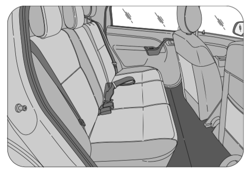
5.3 Second Row Seats
Loading luggage on the seats is dangerous. The luggage can become a projectile that could hit and injure passengers in a sudden stop or collision. Luggage should always be kept on the floor.
To avoid serious injury, do not sit on or place objects on a foldedseat back while the vehicle is moving.
5.4 General Warnings and Instructions- Seat Belts
At least once each month, inspect the seat belt webbing for any cuts, tears, or other signs of wear (such as fraying along the edges). Also inspect the anchors, retractors, and buckles to be sure they are tight and operational.
- All occupants, including the driver, should always wear their seat belt no matter how short the trip in order to minimize the risk of severe injury in the event of a crash. In an accident, an un-belted passenger becomes a projectile, and can cause serious injury to himself or another passenger.
- In a rollover crash, an un-belted person is significantly more likely prone to Injury than a person wearing a seat belt
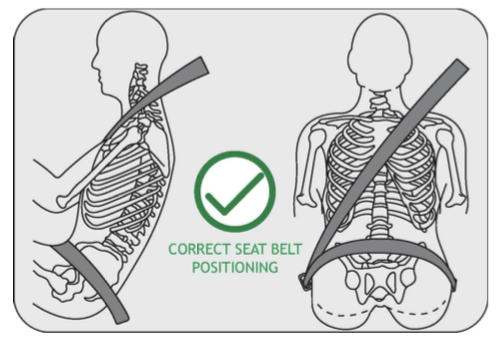
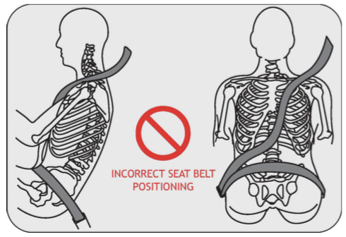
- In order to be properly buckled, you must always sit up straight and keep your feet on the floor in front of you. The lap part must be worn low and tight across your hips, just touching the top of your thighs. While fastening the seat belt, the shoulder strap of the seat belt must pass over your chest and top of your shoulder. It must never touch your neck, face, the side of your shoulder, arm, or pass under your arm. The belt must always be flat against your body and not twisted in any way. Nothing, such as an arm rest, a pocketbook, or any external objects should be between you and the seat belt. Improper wearing of a seat belt will reduce the protection in an accident.
- Seat belts should be adjusted as tightly as possible, consistent with comfort to properly secure the wearer in the seat.
- The seat belts provided for your vehicle are designed for people of adult size, must be properly used and maintained.
- For usage of adult seatbelt to secure children refer to section on manual for child seat positions and use a child restraint systems
- Passengers should not move out of or change seats while the vehicle is moving. A passenger who is not wearing a seat belt can be thrown against the inside of the vehicle, against other occupants, or out of the vehicle during a crash or emergency stop
- Do not use any accessories on seat belts or modify in any way the seat belt system. Devices claiming to improve occupant comfort or reposition the seat belt can reduce the protection provided by the seat belt and increase the chance of serious injury in a crash
- An accident or emergency stop, can damage your seat belt system, even if the accident is “minor”. Please have your Authorized Mahindra Dealer inspect the seat belt system after an accident
- Please be aware that any unsecured item in your vehicle, such as your pet, unsecured child restraint system, a laptop or mobile phones, can become a projectile in the event of an accident or sudden stop, causing injuries to occupants in the vehicle
Never use a damaged seat belt system. A damaged seat belt will not provide protection in an accident, resulting in serious injury.
- Seat belt systems can be prone to abuse. They are not indestructible. They must be handled with care to avoid damage
- Keep the belts clean and dry. Belt retraction may become difficult if the belts and webbing are soiled. If they need cleaning, use a mild soap solution or lukewarm water. Never use bleach dye, or abrasive cleaners. These chemicals will severely weaken the belts
- Retractors in 3-point type seat belts retract the seat belts when not in use. The inertia lock and coil spring allow the belts to remain comfortable on users during normal driving. During accidents or abrupt stops, inertia locks restrict the sudden forward movement of the wearer
Persons with serious medical conditions should also wear a seat belt. Consult your doctor for specific recommendations before travel.
Pregnant women must also wear seat belts. Consult your doctor for specific recommendations.
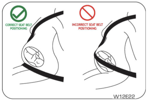
The lap belt should be worn snugly and as low as possible over the hips. The shoulder belt should be worn across your shoulder, but never across the stomach area. When worn properly, the seat belt will protect both the mother and the foetus in an accident or emergency stop.
A pregnant woman should never wear the seat belt across the stomach area. This could lead to serious injuries to the foetus and/or the pregnant mother.
Never wear twisted seat belts. Excessive forces will be transferred from the belt to the wearer, in a collision, resulting in serious personal injury.
Each seat belt is meant for use by one person only. Using one seat belt for more than one person at a time is dangerous. The seat belt will not be able to spread the impact forces properly leading to serious injuries.
Never put a belt around a child being carried on the occupant's lap. This could lead to serious injuries.
- Reduce the possibility of being thrown from your vehicle
- Reduce the possibility of injuries to upper body, lower body and legs during an accident
- Hold the driver in a position which allows better control of the vehicle
Children who are too large for child restraint systems should always occupy the rear seat and use the vehicle seat belts. The lap portion should be fastened snug on the hips and as low as possible and the shoulder strap should be across the child's shoulder, not the neck or face. If you are unable to position the strap across the child's shoulder, the child should remain in a booster seat. Frequently check the seat belt to be sure it remains snug and in position. A squirming child could cause the seat belt to come out of position.
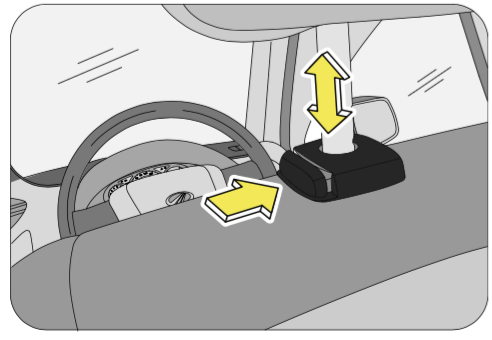
5.5 Seat Belt Height Adjuster (if equipped)
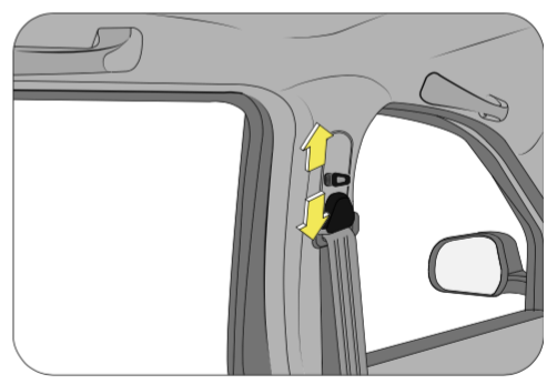
You can adjust the height of the shoulder belt anchor for maximum comfort and safety in both front seats. If the height of the seat belt is too near your neck, you will not be getting the most effective protection. The shoulder portion of the belt should be adjusted so that it lies across your chest and midway over your shoulder nearest to the door and not your neck.
To adjust the height of the seat belt anchor, lower or raise the height adjuster to an appropriate position while pressing the height adjuster button. Release the button to lock the anchor into position. Try sliding the height adjuster to make sure that it has locked into the position.
Adjust the shoulder belt height sitting well back in the seat. Do not adjust the seat belt height while vehicle is in motion.
5.6 Child Restraints
Use a child restraint system only if the child is not big enough to properly wear the seat belts. Else, use the regular seat belt instead of the child restraint system. Seat the child in the rear seat and use the seat belt. According to accident statistics, children are safer when properly restrained in the rear seat than in the front seat. Always secure a child in a proper child restraint system in accordance with age and size of the child as recommended by thechild restraint system manufacturer.
Do not allow children to stand up or kneel on either the rear or the front seats. An unrestrained child could suffer serious injuries during emergency braking or collision.
It is also not recommended that children travel sitting on your lap as it does not provide sufficient restraint.
5.7 Seating positions for Child Restraint System (CRS)
| Mass Group | Seating Positions for CRS Installation | ||||
|---|---|---|---|---|---|
| Front Passenger |
Rear Outboard |
Rear Centre |
Intermediate Outboard |
Intermediate Centre |
|
| Group 0 Upto 10 kg |
X | U | X | X | X |
| Group 0+ Upto 13 kg |
X | U | X | X | X |
| Group I Upto 9 to 18 kg |
X | U | X | X | X |
| Group II Upto 15 to 25 kg |
X | U | X | X | X |
| Group III Upto 22 to 36 kg |
X | U | X | X | X |
| U: Suitable for “Universal” category restraints approved for use in this mass group |
X: Seat position not suitable for children in this mass group |
||||
LOCKS AND KEYS
6.1 Locks And Keys
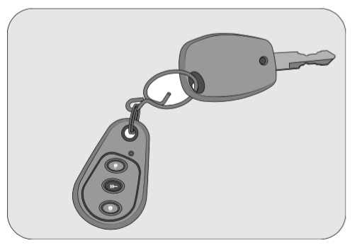
Verito comes with Remote Keyless Entry (RKE) key and Conventional key.
The keys operate all locks in your vehicle including those of the doors and ignition with steering lock. We advise you to keep one of these keys at a safe place for emergency use, but not in the vehicle. Should you lose your keys or if you need replacement keys, they can be ordered through an Authorized Mahindra Dealer.
Never leave the key in the ignition switch with children in the vehicle. A child could switch on the ignition, start the vehicle, operate power windows and other controls, or move the vehicle, resulting in personal injuries of bystanders and/or children seated inside.
Pull the door lever away from the door and push the door outward to open.
Pull the door handle firmly outwards to unlock and swing the door open.
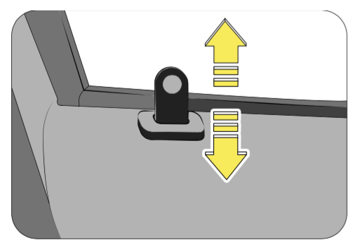
Individual doors can be locked/unlocked from inside by the respective door lock tabs.
Lift the lock tab outwards to unlock or press the tab inwards to lock that particular door.
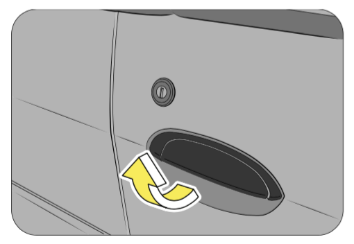
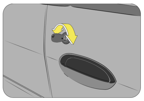
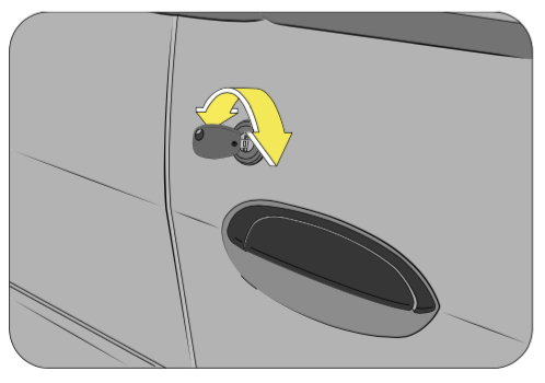
The driver/co-driver door can be manually locked/unlocked from outside by using vehicle key. The key is bi-directional; you can insert it into the key hole either way. Turn the key anti-clockwise/clockwise to unlock the door.
A key hole is provided in the driver door and front passenger door, to lock/unlock the doors manually from outside.
Locking the driver door from outside may activate the central locking system (if equipped), thereby locking ALL the doors of the vehicle. Refer to Central Locking section for further details.
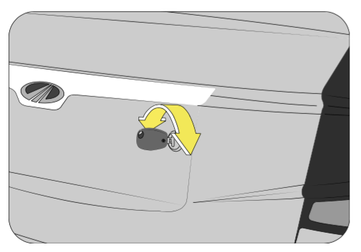
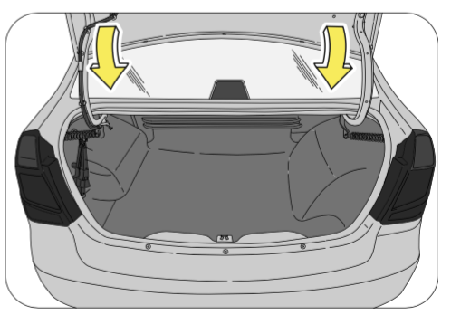
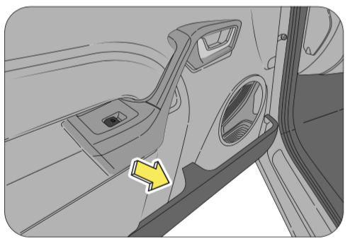
The boot can be manually unlocked from inside by the boot release lever located at the foot of the driver seat (RHS) or by using the key from outside.
To close the boot, lower the boot half way down and allow it fall on its own weight. The boot will lock automatically.
6.2 Central Locking System (if equipped)
All doors of the vehicle can be simultaneously locked or unlocked from the driver door.
6.2.1 Central Locking/Unlocking All Doors from Outside
To lock/unlock ALL the doors from outside using the manual key, turn the key anti-clockwise/clockwise in the driver door key hole.
You can also lock/unlock ALL the doors from outside using the RKE lock/unlock button.
In case the back door is open when the central locking is activated, the back door will not be locked even if it is closed later.
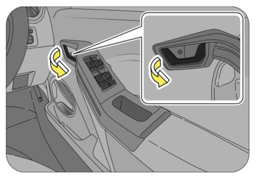
6.2.2 Central Locking/Unlocking All Doors from Inside
Press the bottom of the central lock switch to lock all doors or press the top of the central lock switch to unlock all doors simultaneously.
6.2.3 Child Safety Rear Door Lock
Your vehicle is equipped with left and right side child safety rear door locks. When the lock mechanism is engaged, the rear door(s) cannot be opened from the inside. The door(s) can only be opened from the outside.
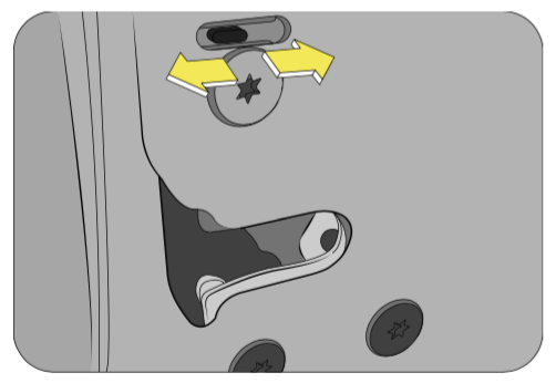
The child safety lock is located on the side face/edge of both the rear doors (when open). To activate/deactivate the child safety lock push the lever left or right till you hear a distinct click indicating the activation/deactivation of the child lock.
If the rear doors are not operable from inside, ensure that the child safety locks have been disabled.
Mahindra strongly recommends that the child safety rear door locks be used whenever there are children traveling in the rear seat.
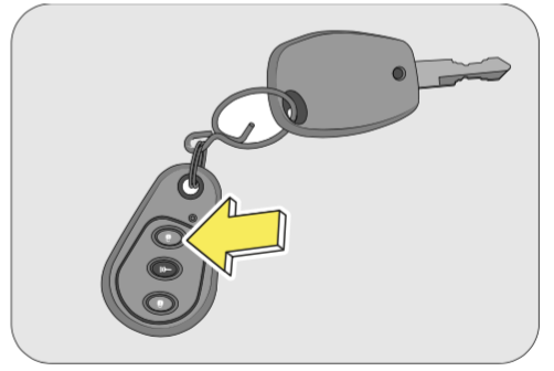
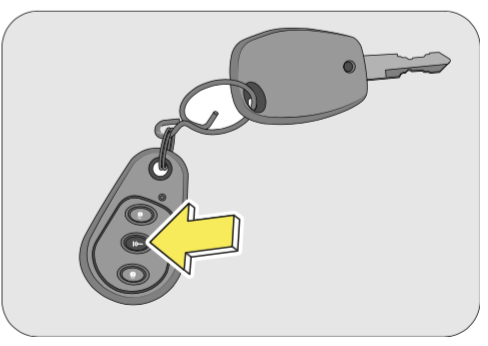
6.3 Remote Keyless Entry (RKE) System
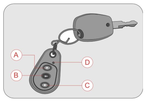
| A | Unlock |
| B | Search (Panic Alarm) |
| C | Lock |
| D | LED |
The front side of the RKE has three control buttons, Unlock, Lock and Search buttons. The Remote Keyless Entry (RKE) system operates on Radio Frequency (RF). You can insert the key into the ignition with either side up.
6.3.1 To Lock and Arm the Vehicle with RKE
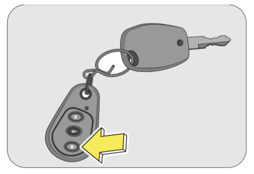
Press the LOCK button on the RKE for locking and arming the vehicle.
Hazard lamps flash once - if all the doors in the vehicle are locked and armed successfully using RKE.
Hazard lamps flash five times along with an alarm - if any of the doors (including bonnet) in the vehicle are open.
6.3.2 Unlock and Disarm the Vehicle with RKE
Press the UNLOCK button on the RKE to unlock and disarm the vehicle.
Hazard lamps flash twice - if there was no theft attempt during the lock (armed) period.
Hazard lamps flash four times along with an alarm - if there was a theft attempt during the lock (armed) period.
Upon the remote lock, if any of the doors are not closed properly or are left open, the hazard lamps will flash five times to indicate the same.
6.3.3 Auto Locking
All doors will get locked automatically when;
- All doors are closed properly, AND
- Vehicle speed is greater than 20 kmph
Auto Locking ON DOOR OPEN — Once the auto lock has been activated, if any door is opened when the vehicle speed is below 5 kmph, then the auto lock will reactivate only if all doors are closed, the vehicle speed goes above 20 kmph and the master actuator is in the unlock position.
Auto Locking ON MASTER ACTUATOR UNLOCK — Once the auto lock has been activated, if the master actuator was unlocked at any vehicle speed, then the auto lock will reactivate only when the vehicle speed goes below 5 kmph and further crosses 20 kmph.
6.3.4 Auto Unlocking
Auto Unlock of all doors will happen when;
- From IGN ON to OFF, OR
- In the event of a crash (only on Airbag Variants)
6.3.5 Auto Re-locking
Auto Re-lock of all doors will happen when;
- No door status change for 45 sec after unlocking the vehicle using RKE
6.3.6 Search (Panic) Function
Press the SEARCH/PANIC button on the RKE to locate the vehicle in a parking lot. Panic alarm can also bring attention to the vehicle and surrounding area, warning about an intruder or seek for help.
When the SEARCH/PANIC function is ON, the hazard lamps flash along with an alarm for 30 sec. In this mode;
- Pressing the SEARCH button again switches OFF the alarm
- Pressing the UNLOCK button switches OFF the alarm and disarms/unlocks all doors
The search function works both during the Locked/Unlocked conditions of the vehicle.
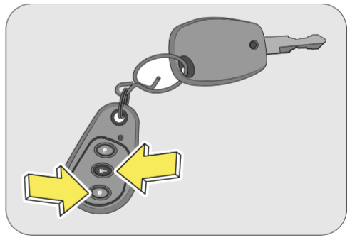
6.3.7 Mute/Un-mute Function
The chirps can be muted / un-muted when the Search operation is in progress. Press the Search button: press the LOCK & SEARCH buttons together for 3 sec. to toggle between MUTE/UN-MUTE mode. Hazard lamps will flash once to indicate the change in status.
In the un-muted condition, alarm chirps would be heard during Auto Re-lock (1 Chirp), RKE Lock when door open (5 Chirps) and RKE Unlock if there was a theft attempt during the lock (armed) period (4 Chirps).
In the mute condition, only hazard would flash and alarm chirps would not be audible.
6.3.8 Theft Alarm
Vehicle enters into alarm mode when there is a change in door status/ignition status provided the vehicle was locked through RKE.
- Alarm time - Pre-alarm (alarm with less intensity) for 5 sec. and continuous alarm for 25 sec. for the first time
- If there is any change in door/ignition status for the second time, the system enters the alarm state for 30 sec. without any pre alarm
After the alarm period, there will not be any alarm again till any further change in the door/ignition status.
The security system (alarm) will be activated only when the vehicle is locked using the RKE. Locking the doors with the mechanical key will not trigger the alarm.
When the vehicle is armed by RKE, opening the door from the inside by operating the door inner handle or opening the door from the outside using the key will be treated as unauthorized activating the vehicle security alarm. If this occurs, the alarm can be disarmed by either pressing the 'UNLOCK' button on the RKE or turning ON the ignition followed by a successful authentication.
6.3.9 Theft Alarm
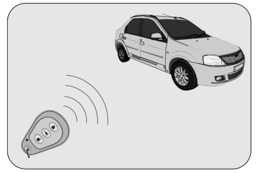
Using RKE, you can lock/arm or unlock/disarm the vehicle from distances approx. 30ft.(9m).
If there is reduction in RKE range, please follow the steps below:
- Check the distance: The RKE may be too far from the vehicle. Stand closer to the vehicle during rain or bad weather
- Check the location: Other vehicles or objects may be blocking the signals. Take a few steps to the left or right, hold the RKE higher, and try again. Moreover, closeness to a radio transmitter such as radio station tower, airport transmitter, mobile or CB radios may lead to reduction in range of RKE
- Check the RKE battery: See battery replacement procedure, given later in this section
- If the RKE is still not working correctly, contact an Authorized Mahindra Dealer
6.3.10 RKE Battery Replacement
If the RKE operation is inconsistent when any of the buttons are pressed it indicates that the RKE battery is weak.
The rear side of the RKE is screw fitted. Using a small screw driver, unscrew and separate the two halves of the casing. The battery type is button type "CR1632 3V cell".
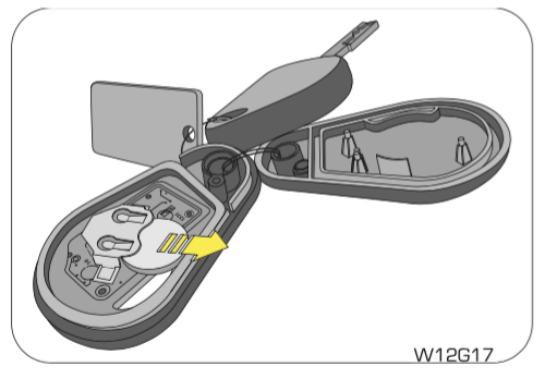
While prying the RKE case, take care not to damage the battery.
Do not touch the battery terminals that are on the back housing or the printed circuit board.
Pull out the battery and discard the same. Insert new battery of same type. While fitting the new battery, ensure the positive side of the batteries face up (for button type). Align both the halves of the RKE and screw to tight fit. Check operation of the RKE.
6.3.11 If RKE is Lost
If you have lost the programmed RKE, contact an Authorized Mahindra Dealer for procuring a new RKE.
While programming a new key set, you will have to submit all the keys available with you to an Authorized Mahindra Dealer.
There is a limitation (max 2 keys at a time) to the number of keys that can be programmed. The minimum time frame required to supply the duplicate keys is 20 days after all the formalities are completed. Please contact the dealer to understand the formalities involved.
If the key is stolen or lost, communicate to an Authorized Mahindra Dealer to de-activate the function of the lost or stolen key. This is essential to avoid unauthorized access using the misplaced key.
Only RKE transmitters programmed to your vehicle electronics can be used for remote locking and unlocking of your vehicle.
6.3.12 Precautions while Handling RKE:
- Do not cover the key grip with any material that cuts off RF waves
- Do not leave the key exposed to high temperatures for a long period, such as on the dashboard or hood under direct sunlight
- Do not put the key in any liquid or wash it in an ultrasonic washer
7 FEATURES AND CONTROL
7.1 Manual Windows (if equipped)
Manual windows can be operated by the glass winder on respective doors. Rotate the glass winder to lower or raise the window.
7.2 Quadruple Switch (if equipped)
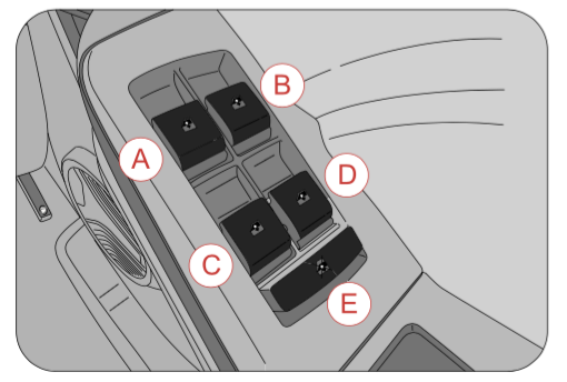
| A | Front Passenger Window Switch | D | Rear RH Window Switch |
| B | Driver Door Window Switch | E | Power Window Lock Switch |
| C | Rear LH Window Switch |
The quadruple power window switch on the driver door armrest/ handle controls the following functions;
- Power window functions of all doors in the vehicle.
- Power window lock/safety switch that enables/disables power window operation of rear doors when operated independently from the respective doors
7.3 Power Windows (if equipped)
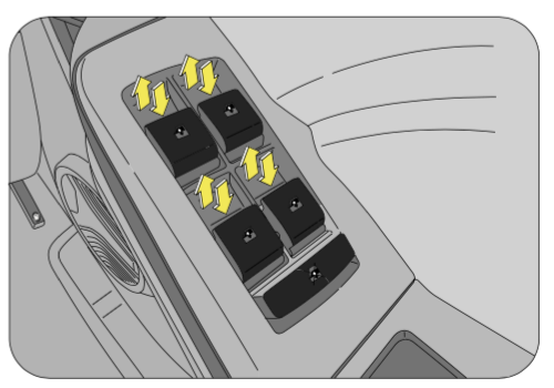
Power windows can be operated only when the ignition is “ON” position. The driver can operate all the power windows in the vehicle through the quadruple switch on the driver door armrest/handle.
Other passengers in the vehicle can raise or lower their respective window glasses individually by using the separate switches provided on each of the door trim pads/arm rests.
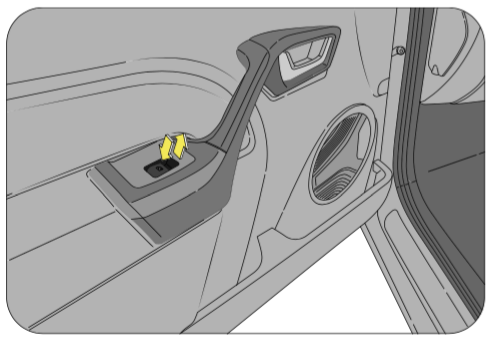
To lower/raise the window glass push/pull the power window switches respectively.
Do not operate the power windows frequently when the vehicle is OFF. This will drain the vehicle battery.
If you operate the switch often during a short period of time, the system might become inoperable for a certain duration to prevent damage due to overheating. The system will return to normal functioning shortly. It is recommended to operate one window switch at a time.
While operating the power windows, check for obstructions like head, hand, etc. which may lead to personal injuries.
7.3.1 Power Window Lock Switch
The main power window quadruple switch in the driver door trim has a power window lock switch to enable or disable operation of both LH and RH rear passenger window switches.
To disable the rear power windows, press the window lock switch down. To revert to normal operation, press the window lock switch again.
7.4 Mirrors
7.4.1 Manual ORVM (if equipped)
Integrated exterior rear view mirrors on both the sides facilitate maximum rear view information to the driver.
Fold both the ORVM’s manually while parking the vehicle in congested roads or narrow parking slots. This avoids hindrances and safeguards the ORVM’s.
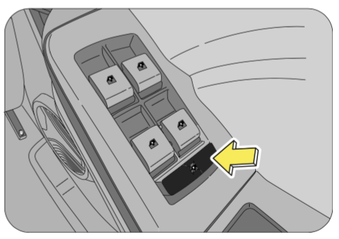
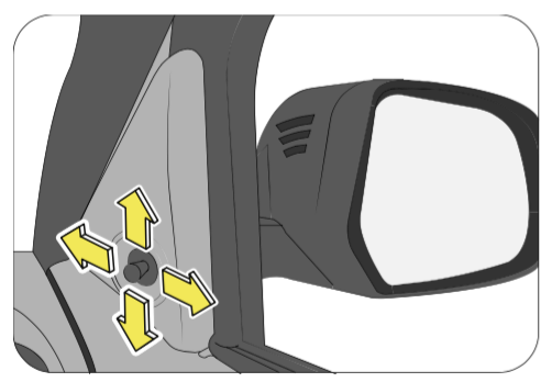
The mirrors can be adjusted for a clear rear view using the joystick on the ORVM pad trim.
7.4.2 Electric ORVM(if equipped)
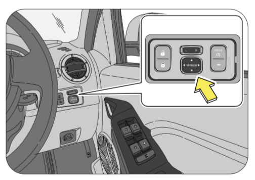
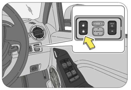
The ORVM adjustment switch (perimeter switch) and the Left (L)/ Right (R) ORVM selector switches are located on the RHS instrument panel near the central lock switch.
Both the ORVM’s can be electrically adjusted by the ORVM adjustment switch.
Do not overestimate the distance of the objects that you see in the mirrors. Objects seen in convex mirrors are much closer than they appear.
Use the ORVM L/R selector switch, to select Left/Right side exterior mirror respectively. The ORVM adjustment switch adjusts the selected ORVM in the required direction. Lock the ORVM’s by setting the ORVM selector switch to the middle position.
7.4.3 Interior Mirror
The interior rear view mirror provides the rear vehicle view information to the driver and also aids during reversing.
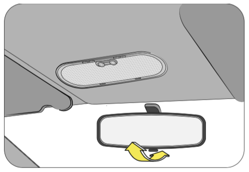
The interior mirror has day and night (anti-glare) positions. The night position reduces glare from head lamps of vehicles behind you. Flip the tab on the bottom edge of the mirror to select the day or night position.
7.5 Utility Holders
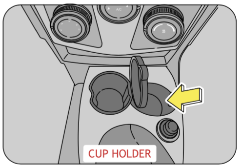
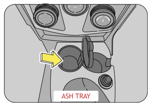
7.5.1 Cup Holder/Ash Tray (if equipped)
The cup holder in the floor console can be used to store small cups, bottles, etc. An ash tray is also provided in the cup holder. Lift the lid to use the ash tray. To empty the ash tray, firmly pull the ash tray up. Similarly, to put it back, gently press the ash tray back in the same location.
Use caution when using the cup holders. A spilled beverage that is very hot can injure driver or passengers. Spilled liquids can also damage interior trim and electrical components.
Never place objects other than cups or cans in the cup holder. These objects can be thrown out in the event of a sudden stop or an accident, possibly injuring the passengers in the vehicle.
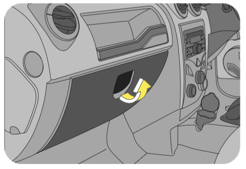
7.5.2 Glove Box
The glove box can be opened by gently lifting the lock and lowering the lid. To close, gently close the glove box lid and press to lock.
Do not overload the glove box.
Do not store loose or small metal objects inside glove box. This will lead to rattling while the vehicle is driven on bad roads.
To avoid the possibility of injury in case of an accident or a sudden stop, the glove box lid should be kept closed when the vehicle is in motion.
It is recommended to keep copies of all vehicle documents along with the owner’s manual kit in the glove box for reference when needed.
7.5.3 Instrument Panel Storage
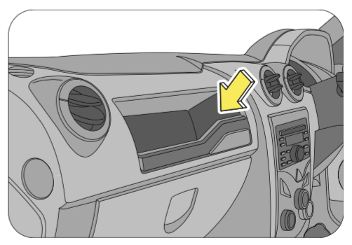
A storage compartment above the glove box can be used for storing small items like wallets, mobiles, etc.,
7.5.4 Magazine Holder
Magazine holders are located on both the front door lower trims. You can use them to store magazines, maps, papers, small books, etc.
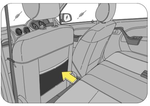
The seat back pocket is located on the back of the front passenger seat for holding light weight papers/books/magazines, etc.
To avoid injury, do not place large or hard objects in the seat back pockets. Do not put more than 1 Kg weight in seat back pockets.
7.5.5 Instrument Panel Storage
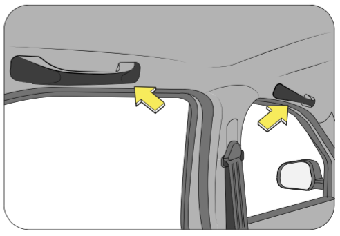
Grip handles are provided above the front (passenger only) and second row outboard seats.
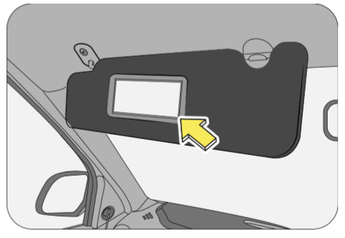
7.6 Sun Visor
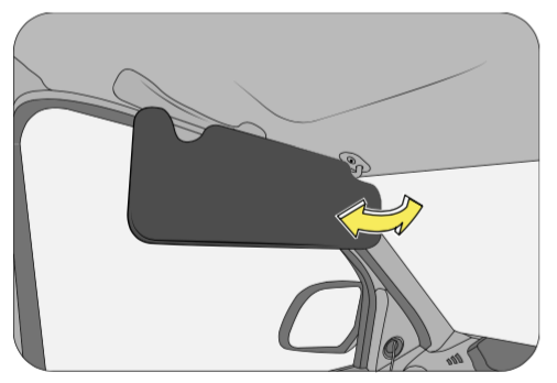
Sun Visors are provided for both driver and co-driver above the windshield. The sun visors can be used for either frontal or sideward shade, to reduce glare or to shut out direct rays of the sun.
Pull down the sun visor to block the glare of the sun. The sun visor can also be swivelled to the side as shown.
A vanity mirror is provided on the back of the co-driver sun visor.
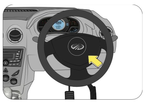
7.7 Horn
Press the pad on the steering wheel to blow/sound the horn. The horn do not function when the ignition has been switched OFF.
7.8 Interior Lamps
Interior lamps comprise of front roof lamps and map reading lamps.
7.8.1 Front Roof Lamp
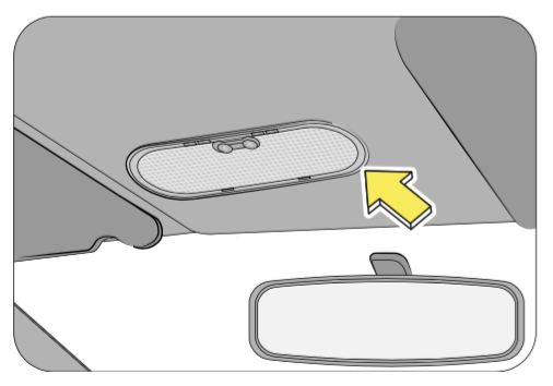
The front roof lamp is located in the roof console above the interior rear view mirror. The roof lamp can be switched ON/OFF by the switch on the lamp.
The roof lamp has 3 positions; OFF, AUTO/DOOR & ON.
(A) OFF: The roof lamp remains OFF permanently irrespective of the door status
(B) AUTO: The roof lamp remains OFF if all doors are closed, and ON if any door is open
(C) ON: The roof lamp remains permanently ON irrespective of the door status
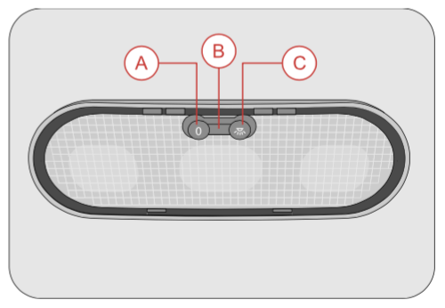
| A | Permanently OFF | B | AUTO Mode |
| C | Permanently ON |
Do not leave the roof/map reading lamp in permanent ON mode. This will drain your vehicle battery.
7.8.1 Front Map Reading Lamp (if equipped)
The front map reading lamps are integrated in the roof lamp above the interior rear view mirror. The map reading lamps can be individually switched ON/OFF by the switches in the respective lamp.
7.8.1.2 Boot Lamp
The boot lamp aids you in night trips while loading/unloading luggage in the boot. It is switched on automatically when the boot is opened (provided the parking lamps are switched ON).
7.8.3 Power Outlet (if equipped)
A 12V power supply socket is provided for power take OFF in the floor console next to the cup holder. Electrical equipment/ appliances like mobile phone charger, cigarette lighter, etc. can be used in the outlet.
The power socket function only when the ignition is in ACC or ON positions. It is recommended to use the power socket only when the vehicle is ON to avoid battery drain.
To avoid serious injury:
- Close the power outlet cap when not in use
- Do not allow children to use or play with the power outlet
- When using electrical appliances, strictly follow the manufacturers instruction manual
- Never insert inappropriate or badly fitting plugs into the power outlet
Do not modify, disassemble or repair the power outlet in any way. Doing so may result in unexpected malfunction or fire, which could cause serious damage to equipment and/or personal injuries. Contact an Authorized Mahindra Dealer for any necessary repairs.
To prevent injuries and accidents, secure all electrical appliances before use. Do not use any appliance that may:
- Distract the driver while driving, or hamper safe driving
- Result in a fire or burn injuries due to the appliance rolling, falling or overheating
- Use the power outlets only when the vehicle is running. Remove the plug from the power outlet after using the electric device. Using the power outlets when the vehicle is OFF or leaving the electric device plugged in for many hours may cause the battery to drain
- Do not use the power outlet to connect electric accessories or equipment that are not designed to operate on 12V
- Some electronic devices can cause electronic interference when plugged into the power outlet. These devices may cause excessive audio noise and may interfere with other electronic systems or devices in your vehicle.
7.9 Exterior Lamps
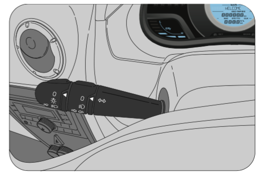
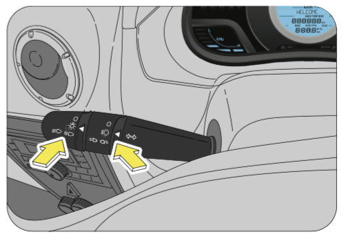
7.9.1 Lighting Control Stalk
The lighting control stalk is located on the left hand side of the steering wheel and is a part of the combination switch. It controls operations of parking lamps, head lamps, head lamp beam selection, high beam flashing, front fog lamp and turn signals.
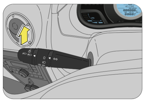
7.9.2 Turn Signals
| A | Turn Signal— Right | B | Turn Signal —Left |
- Push the lighting control stalk clockwise (to stop position A) to indicate a right turn. The instrument cluster arrow lamp pointing towards the right flashes along with the right side turn signal lamps with chime indicating your intention of turning towards right
- After you have completed your right turn, the stalk will automatically return to the neutral position. Both the right turn lamp and the right turn signal lamp switch OFF
Push the lighting control stalk anti-clockwise (to stop position B) to indicate a left turn. The instrument cluster arrow lamp pointing towards the left flashes along with the left side turn signal lamps with chime indicating your intention of turning towards left
After you have completed your left turn, the stalk will automatically return to the neutral position. Both the left arrow lamp and the left turn signal lamp switch OFF
If the turn signal lamps on the instrument panel flash faster than normal, there may be a possibility that one or more of the turn signal lamp bulbs have blown. Replace the blown bulb immediately.
You can signal a lane change by moving the lighting control stalk clockwise or anti-clockwise to the limit point of free movement of the lever and releasing it once you change the lane.
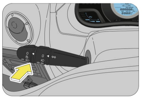
7.9.3 Lamps OFF
Rotate the outer rotary switch on the lighting control stalk aligning the "arrow" on the stalk to "0" on the switch to switch OFF all lamps.
7.9.4 Parking Lamps ON
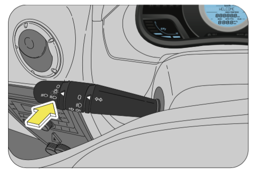
Rotate the outer rotary switch on the lighting control stalk aligning the "arrow" on the stalk to the “1st detente” position on the switch to switch ON the parking lamps.
The tail lamp, license plate lamp, side marker lamps, instrument panel illumination lamps and all interior switches are also activated when the Parking lamp is switched ON.
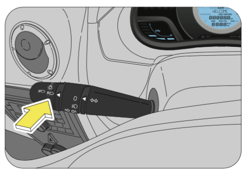
7.9.5 Head Lamp ON
Rotate the outer rotary switch on the lighting control stalk aligning the "dot" on the switch to the "2nd detente" position on the stalk to switch ON the head lamps.
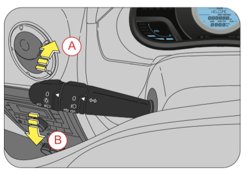
7.9.6 Head Lamp Low/ High Beam
To change the beam selection, switch ON the head lamp, lift the lighting control stalk up and release. Lifting & releasing the stalk again toggles between low beam and high beam. The head lamp high beam telltale lamp illuminates in the instrument cluster when it is ON.
7.9.7 Head Lamp Flash
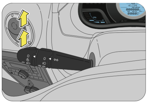
Pull the lighting control stalk all the way up towards the steering wheel to instantaneously flash the head lamp high beam.
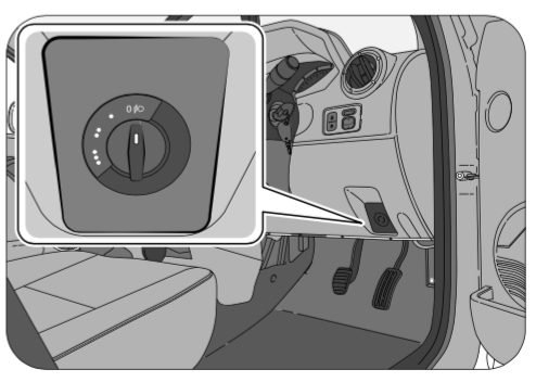
7.9.8 Head Lamp Leveling System
When the vehicle is either fully or partially loaded, it may have an upward inclination disturbing the head lamp aiming. A correct head lamp setting provides good visibility to the driver with minimum inconvenience to other road users.
To properly aim the head lamp beam, use the head lamp leveling switch. This switch is located below the steering column shroud in the instrument panel. This switch has four positions marked as 0, o, oo & ooo. The last position “ooo” is DUMMY position. Select the suitable switch position depending on the pay load as advised in the table.
| Switch Position | Vehicle Loading Condition |
|---|---|
| 0 | Basic setting: luggage compartment empty and only the driver on board or with one front passenger |
| * | Luggage compartment empty, 1, 2, 3 passengers |
| ** | Luggage compartment full, 3 passengers or with driver only |
| *** | DUMMY |
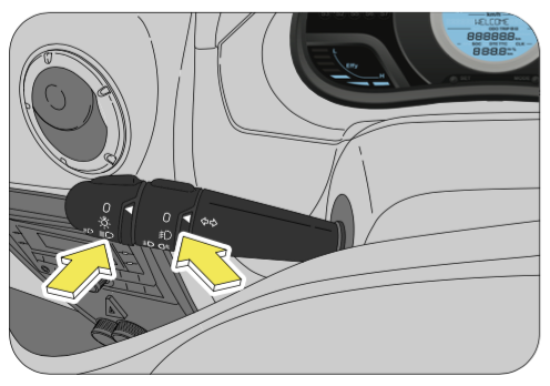
7.9.9 Fog Lamps (if equipped)
Fog lamps are to be used along with head lamp low beam, to improve the vision during foggy and misty conditions.
Your vehicle is equipped with front fog lamps only. The lighting stalk may display the rear fog lamp symbol. This is future protected and currently does not function.
Align the “OFF” of inner rotary switch on the lighting control stalk to the “arrow” mark on the inner fixed stalk as shown to switch OFF the fog lamps.
To switch ON the front fog lamps, switch ON the ignition and the parking lamps. Turn the inner rotary switch on the lighting control stalk to align to the inner fixed stalk as shown.
The front fog lamp indicator in the instrument cluster indicates the operation status.
Fog lamps will turn ON only if parking lamp is ON.
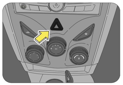
7.9.10 Hazard Warning Lamp
The hazard warning lamp switch is located in the center bezel switch bank on the instrument panel below the audio unit.
To turn the hazard warning lamp ON, push the switch in. All the turn signal lamps flash. The instrument cluster turn indicator lamps also flash indicating the same. To turn OFF, push the switch again.
Use the hazard warning lamp when your vehicle is stationary or to warn other road users to be cautious while passing your vehicle.
The turn lamps do not work when the hazard warning lamps are operational.
7.10 Windshield Wipers
7.10.1 Wiper Control Stalk
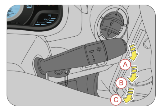
| A | Intermittent Wipe |
| B | Normal Wipe |
| C | Fast Wipe |
7.10.2 Intermittent Mode
Intermittent wiping is selected when the wipe control stalk is pushed down to position A. In this mode, the wiper operates on preset intervals.
7.10.3 Normal Mode
Push the wipe control stalk down to the position B to operate the wiper at normal speed.
7.10.4 Fast Mode
Push the wiper control stalk down to position C to operate the wiper at high speed.
The wipe/wash function can be activated only when the ignition is in “ON” position.
7.10.5 Windshield Washer
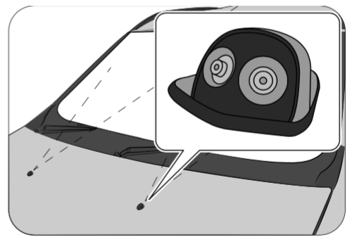
Pull/Lift the wiper control stalk towards the steering wheel from any position to activate wash function. Washer fluid from front washer reservoir is pumped and sprayed onto the windshield. Hold the stalk in position for continuous spray of washer fluid.
The wiper automatically wipes the windshield once after every wash. There are two nozzles with adjustable jets on the hood of the vehicle.
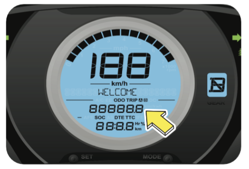
7.11 Instrument Cluster
| A | Speed Graph Display | F | DTE/SOC/CLK |
| B | Digital Speedometer | G | Set Button |
| C | Gear Indicator | H | Trip meter/ Odometer |
| D | State-of-Charge (SOC) | I | Efficiency Gauge |
| E | Mode Button |
The instrument cluster comprises of the Tachometer, Speedometer, Tripmeter, Message Display, Reset Button, Odometer, State-of-charge (SOC), Efficiency gauge, Gear position indicator, Warning lamps and Telltale indicators.
7.11.1 Speedometer
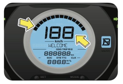
The speedometer indicates the real time road surface speed of the vehicle in kilometers per hour. There are two speedometers in the cluster; one is a speed graph display which increase 2 segments for every 10 kmph increase in speed and the other is a digital speedometer readout.
| Displayed Speed | No of segments in graph |
|---|---|
| 0 | All OFF |
| 1–14 | 2 segments |
| 15–29 | 4 segments |
| 30–44 | 6 segments |
| 45–59 | 8 segments |
| 60–74 | 10 segments |
| 75–89 | 12 segments |
| > 89 | All ON |
The vehicle speed is affected by size of the tires used. If the size of the tires are changed from those fitted at the factory, the speedometer might not display the correct road surface speed and distance travelled.
7.11.2 Odometer
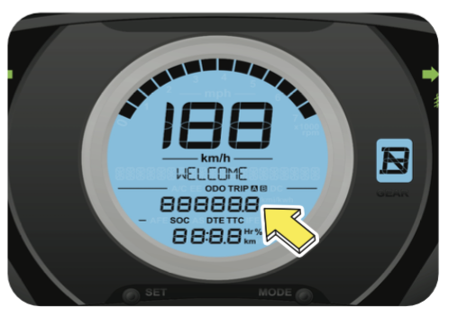
The odometer records and displays the total distance traveled in kms. Odometer cannot be reset. It is toggled by the mode button.
7.11.3 Trip meter
Trip meter displays the elapsed distance travelled since the last trip reset. There are two trip meters A & B and it is toggled by the mode button. They can be reset by a long press of the set button.
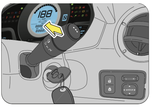
7.11.4 Set and Mode Buttons
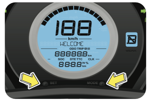
- The SET button is used to toggle between ODO -> TRIP A -> TRIP B.
- The Mode button toggles between DTE —> SOC —> TTC —> CLK.
DTE: DTE is the default screen which indicates approximate number of kilometers that can be driven with available charge
SOC: displays the state of charge in the batteries
TTC: indicates approximate time to full charge.
CLK: displays the time.
7.11.5 State-of-Charge (SOC) Gauge
The SOC indicates the current percentage of charge in the batteries. This varies with changes in weather, load on battery and driving pattern.
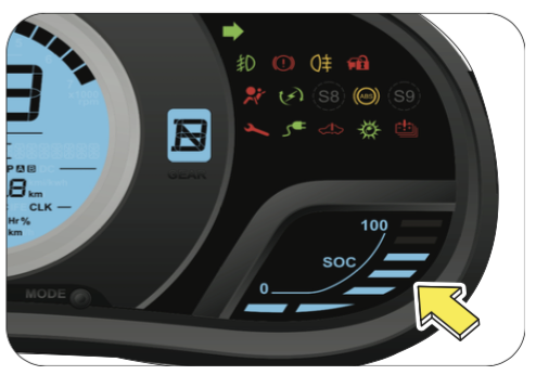
| Bars | Percentage Charged |
|---|---|
| 1st bar FLASH | 5–17 % |
| 2nd bar ON | 21 % |
| 3rd bar ON | 36 % |
| 4th bar ON | 51 % |
| 5th bar ON | 66 % |
| 6th bar ON | 81 % |
| All Bars ON | 95 % |
7.11.6 Efficiency Gauge
The efficiency gauge indicates energy consumption level during the drive. The higher the efficiency more bars towards “H” are illuminated.
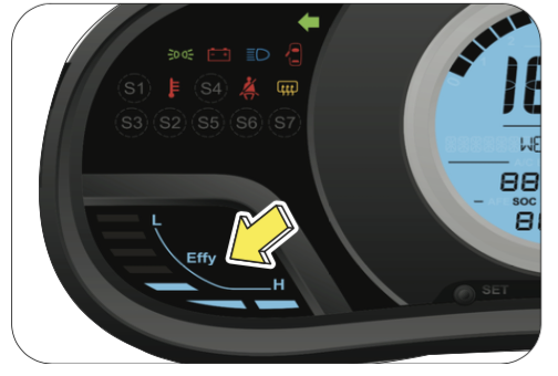
| Efficiency % | Bars |
|---|---|
| 0 | All bars OFF |
| 1–15 % | 1st bar ON |
| 16–30 % | 2 bars ON |
| 31–45 % | 3 bars ON |
| 46–60 % | 4 bars ON |
| 61–75 % | 5 bars ON |
| 76–85 % | 6 bars ON |
| > 85 % | All Bars ON |
7.11.7 Message Centre
The message centre display the Welcome message and also critical/informative messages.
| SI No | Message | Description |
|---|---|---|
| 1 | INSERT PLUG FULL | Check and Insert charge port cable completely |
| 2 | CHARGING | Vehicle is charging |
| 3 | CHARGE COMPLETE | Vehicle charged completely |
| 4 | CHARGE FAULT | Charge is stopped due to malfunction in the vehicle |
| 5 | CHARGE TERMINATE | Charge is stopped by using mobile application* |
| 6 | UNPLUG CAR | Charge cable to be removed before you turn on the ignition key |
| 7 | SHIFT GEAR TO "N" | Push the gear lever to 'N' (neutral) position after successful authentication, if the gear position is other than N |
| 8 | RESTART | In case t he authentication fails restart again |
| 9 | POWER SAVE MODE | When t he SOC becomes less than 10% the vehicle enters into limp home and the HVAC is turned off |
| 10 | ACTIVATE REVIVE | When SOC becomes 0% and revive attempts are present then request revive through mobile* or cluster |
| 11 | CHARGE CAR | When SOC becomes 0% and all the revives are used then Plug the vehicle for charge |
| 12 | GO SLOW | Slow down the car if the temperature light turns on the cluster |
| 13 | STOP CAR | Stop the vehicle for sometime if this message comes on the cluster |
| 14 | SERVICE DUE | If scheduled service is due then this message will appear for 2 minutes at the start of drive in every cycle |
| 15 | CHECK BRAKES | Press the brakes once and the message goes off |
| 16 | SAFE MODE | In case of any fault in EV drive system car will continue to drive with low performance |
| 17 | DRIVE FAULT | In case of any fault in EV drive system car will not move from start |
| 18 | REVIVE | During Revive activation process thus message will flash |
| 19 | WARM UP BATTERY | If battery temperature is below 0o C this message will appear and driving range is low |
| 20 | REVIVE UNSUCCESSFUL | If revive request is not successful then this message will appear |
| 21 | INACTIVE AFT 2 CY | If vehicle is deactivated using mobile application* then this message appear in the next drive cycle |
| 22 | INACTIVE AFT 1 CY | If vehicle is deactivated using mobile application* then this message appear in the next second drive cycle |
| 23 | INACTIVE | If vehicle is deactivated using mobile application* then this message appear in the third drive cycle and vehicle cannot be driven |
| 24 | RELEASE THROTTLE | Do not press the throttle and authenticate the vehicle |
| 25 | STOPPING | When SOC= 1% this message appears in the cluster and vehicle stops at 0% SOC |
| 26 | REVIVE MODE | After the revive is successful this message appears until SOC = 1% |
| 27 | ISO FAULT | During isolation failure this message appears, vehicle should be taken to service |
| * if applicable (through mobile App only) | ||
7.12 Warning Lamps in the Instrument Cluster
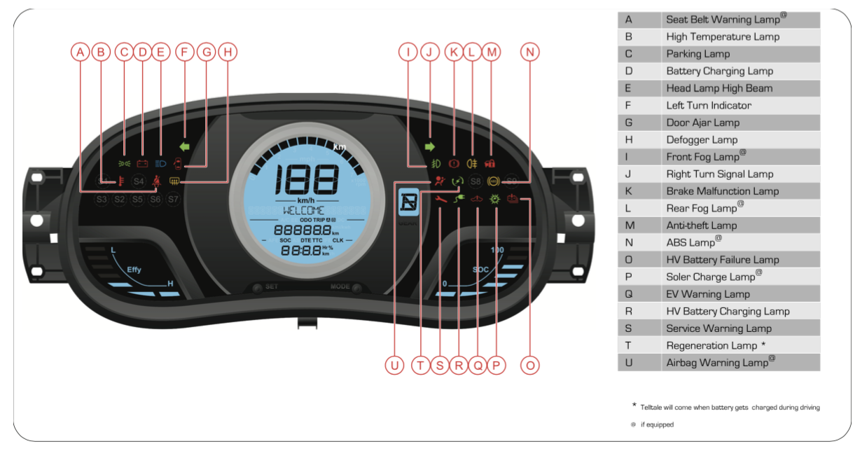
| A | Seat Belt Warning Lamp@ |
| B | High Temperature Lamp |
| C | Parking Lamp |
| D | Battery Charging Lamp |
| E | Head Lamp High Beam |
| F | Left Turn Indicator |
| G | Door Ajar Lamp |
| H | Defogger Lamp |
| I | Front Fog Lamp@ |
| J | Right Turn Signal Lamp |
| K | Brake Malfunction Lamp |
| L | Rear Fog Lamp@ |
| M | Anti-theft Lamp |
| N | ABS Lamp@ |
| O | HV Battery Failure Lamp |
| P | Soler Charge Lamp@ |
| Q | EV Warning Lamp |
| R | HV Battery Charging Lamp |
| S | Service Warning Lamp |
| T | Regeneration Lamp * |
| U | Airbag Warning Lamp@ |
* Telltale will come when battery gets charged during driving
@ if equipped
7.12.1 Turn Lamps

The turn lamp arrow in the instrument cluster flash showing the direction indicated by the turn signals. A sudden increase in the rate of flashing indicates failure of one or more of the lamp bulbs. Have them replaced as soon as possible.
7.12.2 Airbag Warning Lamp (if equipped)

The airbag warning lamp in the instrument cluster illuminates when the ignition is switched ON and goes OFF in about 3 seconds. If the lamp remains ON continuously or flash’s intermittently, contact an authorized Mahindra dealer immediately.
Following conditions indicate airbag malfunction:
- Lamp fails to go OFF
- Lamp does not illuminate at all
- Illuminates while driving
Contact an authorized Mahindra dealer immediately when the airbag warning lamp indicates a system malfunction. The airbag may not deploy when needed, which could result in serious or fatal injury, or it might deploy unexpectedly and unnecessarily, which may result in personal injury.
7.12.3 Front Fog Lamp (if equipped)

The front fog lamp telltale indicates the status of the front fog lamp. The front fog lamp can be switched ON only when the parking lamp is ON.
7.12.4 Immobilizer Lamp

Once the ignition is turned OFF, the security lamp will
blink at a fast rate frequency indicating the vehicle is
secured against unauthorized start of the vehicle.
When the vehicle is locked using RKE, security lamp will blink at a
slow rate frequency which will indicate that antitheft system is
armed and unauthorized door entry to the vehicle will trigger alarm.
At ignition ON, the security lamp blinking continuously indicates a
malfunction in the vehicle immobilizer system. Contact an
Authorized Mahindra Dealer immediately.
7.12.5 High Temperature Warning Lamp
The high temperature warning lamp flashes when the temperature in motor, motor controller, HV battery and charger is high.
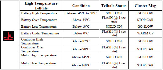
Do not continue driving the vehicle with an overheated motor. This may result in damage to the components and will not be covered by the warranty.
7.12.6 Rear Windshield De-mister Lamp (if equipped)
The rear windshield de-mister lamp illuminates to indicates the status of the de-mister. Contact an authorised Mahindra dealer if the lamp fails to illuminate.
7.12.7 Parking Brake Lamp
The lamp illuminates when: Parking brake is engaged or Brake fluid level is low
If the lamp illuminates while driving, do the following:
- Check if the parking brake is engaged. If yes, disengage it
- Check if brake fluid level is low. If yes, top-up brake fluid (DOT 4) to the required level
If the brake lamp still continues to illuminate, immediately get the vehicle checked at an Authorized Mahindra Dealer.
Clean the top of the brake fluid reservoir before removing the
cap. Make sure no dirt, impurities or other items fall into the
reservoir. Do not leave the cap off for more than a few minutes.
Any contaminants, impurities or moisture in the brake fluid can
affect brake operation, resulting in an accident.
If the brake warning lamp comes ON while driving, the brake
system might not be working properly. The pedal might be
harder to operate or might go closer to the floor and it can
take longer to stop. Pull off the road carefully and stop the
vehicle. Contact the nearest Authorized Mahindra Dealer for
checks or repairs.
Driving the vehicle with the brake warning lamp ON or when you
suspect brake trouble is very dangerous and could result in
serious injuries. Contact an Authorized Mahindra Dealer for
checks or repairs.
7.12.8 Head Lamp High Beam Lamp
The head lamp high beam telltale illuminates whenever the head lamps are switched ON to high beam or when the head lamp flash is used.
7.12.9 Anti-lock Brake System (ABS) Malfunction Lamp (if equipped)
The ABS malfunction lamp illuminates when the ignition is switched ON and goes OFF after about 3 seconds. If the ABS malfunction lamp continues to remain ON or illuminates while driving, ABS will not operate. But the brake system will still operate conventionally. In this condition, the wheels can lock during severe braking. Have the vehicle checked by an authorized Mahindra dealer as soon as possible.
7.12.10 Battery Charging System Warning Lamp
This lamp illuminates when the ignition is switched ON and goes out as soon as the vehicle is started. If the lamp continues to remain ON even after starting the vehicle, it is an indication that the battery is not being charged or there is a malfunction in DC-DC converter. Contact an Authorized Mahindra Dealer for further assistance.
Auxiliary battery will be charged by DC converter present inside the charger.
7.12.11 HV Battery Failure Lamp
The HF battery failure warning lamp illuminates when the battery is not being charged or when there is a malfunction in the charging system. Contact your nearest Authorized Mahindra Dealer immediately
7.12.12 EV Warning Lamp
The EV warning lamp illumination could be due to a temporary condition detected by IEMS (On board computer) and will turn off if problem gets healed. In case it continues to stay on contact your nearest Authorized Mahindra Dealer immediately.
7.12.13 Seat Belt Warning Lamp
The seat belt warning lamp illuminates reminding the driver to fasten the seat belt when the ignition is ON. The lamp will continue to illuminate till the driver fastens the seat belt properly.
7.12.14 Door Ajar Warning Lamp
The door ajar warning lamp illuminates and the buzzer chimes 3 times when any of the doors including the hood and back door are open during ignition ON. The lamp goes OFF when all the doors are closed properly.
7.12.15 HF Charging Lamp
The HF charging lamp blinking indicates charging and solid indicates fully charged status.
7.12.16 Re-genaration Lamp (if equipped)
The regeneration lamp comes ON when the battery is being charged during vehicle running condition.
7.12.17 Solar Charge Lamp (if equipped)
The solar charge lamp indicates the charging status when charged through solar energy.
7.12.18 Service Indicator
The service indicator illuminates when your vehicle needs to be serviced. Take your vehicle to the nearest Authorized Mahindra Dealer for service. It will be reset in service centre once your vehicle has been serviced.
7.13 Radio Frequency ID (RFID) Tag
Your vehicle is fitted with a RFID tag as per CMVR regulations on front windshield.
RFID tag may be used for Electronic Toll Collection (ETC).
Do not peel or remove the RFID.
8 CHARGING
8.1 Vehicle Charging
Car requires charging of battery power pack once energy stored in it gets depleted. There are two methods of charging battery power pack;
- Normal charging — Port located on the RHS over the right rear wheel arch
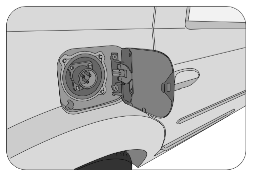
- Fast charging (if equipped) — Port located on the LHS over the left front wheel arch/fender
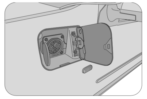
Time to charge the battery pack varies based on the state of charge, ambient & battery temperature. Hence charging time specified is an estimate and may vary.
- In case you use any medical electric devices like implantable cardiac pacemaker or cardio vascular defibrillator, do check with electric medical device supplier / manufacturer on concerns of effects that EV charging or discharging system may have on implanted devices prior to their operation.
- It is also advised not to stay in vehicle or access the vehicle during charging as it may affect function of electric medical devices and could result in personal fatal injury.
- Make sure that there are no foreign particles or water traces in charge plug or port as any of these can result in electric short circuit or shock causing serious injury or death. Hence do not touch metal contacts on cable or plug.
- Do not drag or keep charge cable close to any heat source.
- Ensure that power socket is switched off before accessing the charge cable.
- Do not handle charger cable or port with wet hands as it may cause electric shock resulting in injury.
- Do not pull or twist cable, always remove it by holding charger port handle after switching off plug point.
- Do not modify port or cable as it may cause fire hazard.
- In case you observe an unusual odor or smoke coming from vehicle, do immediately stop charging process.
- Always make sure that the charger cable is disconnected from on board charge port prior to drive.
- Charging may affect operation of worn or implanted electric medical devices and could result in serious injury or death.
Car can be charged using house charging unit installed at home or at office or with charge cable provided with the vehicle.
Always charge your car using charge cable supplied with vehicle. It normally takes approximately 8– 9 hrs to full charge from completely discharged battery.
A separate fast charge port is provided in front LH fender to charge battery power pack quickly in 120 minutes time. Fast charging cannot be done at home, this charging can be availed at places where ‘Fast charge’ stations are available exclusively for Mahindra vehicles. It is recommended to use Fast charging only in emergency needs and not always.
8.2 Wall Mount Charger (WMC) (if equipped)
Always use installed ‘WALL MOUNT CHARGER” for charging your car at home or office. Purchase a charge cable from dealer to charge your car at other charge points having proper earth.
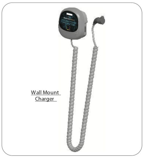
8.3 Normal charging
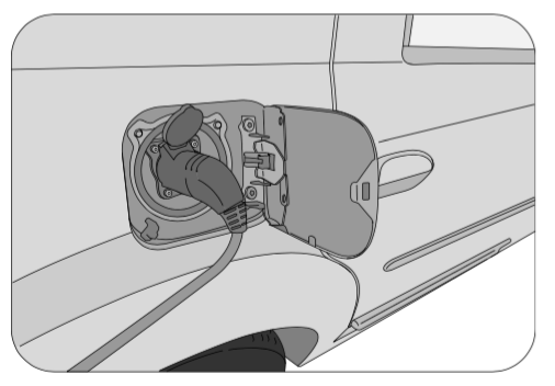
Charging your car is safe and simple in just 4 steps:
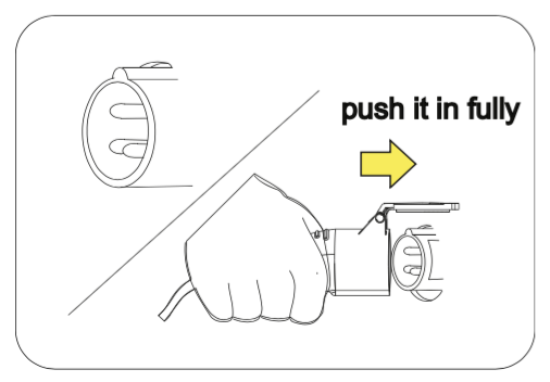
- Ensure parking brake is applied and ignition key is removed.
- Take out the charge cable from vehicle.
- Plug in one side of charge cable to vehicle charge port and ensure that cable is pushed in completely.
- Plug in other end into charge point on wall socket and turn on power supply switch.
- Ensure the charge indication in the cluster is ON
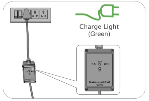
Vehicle is now on charge. Charge Light (green) indicator will flash & turns solid once charging is completed.
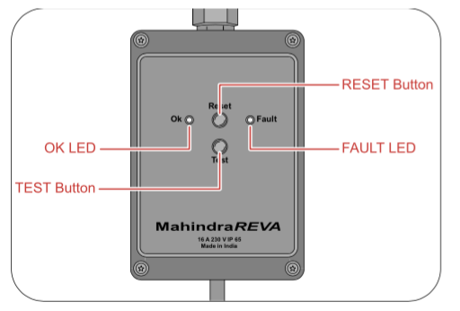
Green LED light indicates normal charging and healthy earth in charging circuit.
Red LED light indicates fault in charging circuit for under or over voltages and residual current trip fault.
In event of earth leakage or any other faults it will trip. Press to reset after rectifying the issue.
Press to evaluate healthy condition of electric power supply once in a while if cable is being used sparingly that also shows cable is working OK or faulty.
Once charging is completed, first switch off power supply, then remove charging cable from plug point and on-board charge port. Roll and keep charge cable in its location.
8.4 Charge Duration
Time taken for charging can vary up to 8– 9 hrs from complete discharged condition. Charging duration may vary:
- If battery power pack temperature has reached its maximum limit, charging will slowdown and will take longer time to charge
- If battery power pack temperature reaches minimum limit (less than 10° C), charging will slowdown and will take longer time to charge.
8.5 Ideal Time to Charge
Vehicle can be charged anytime with availability of charging facility, however charging can be done at suitable time that has following advantages:
- Normally most of requirements for city mobility are during day, hence charging at night will not interfere in daily travel plans.
- At night, ambient temperature is less which is ideal for battery charging.
8.6 Intelligent Charging System
This vehicle has unique Intelligent Energy Management System [IEMS] that controls energy flow from mains to battery power Pack through on board charger. It will optimize energy consumption to charge battery pack completely.
Further more if there is voltage fluctuation or an interruption in main power supply, system remembers point at which charging was interrupted and resumes charging from there onwards.
8.7 Fast Charging (if equipped)
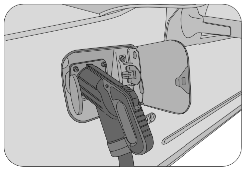
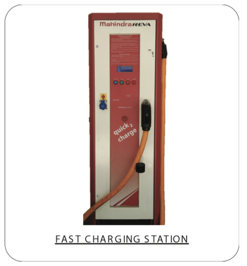
Car is fitted with an onboard fast charging port which uses high DC (current) supply for charging. This requires DC fast charging station installed exclusively for Mahindra vehicles at various locations in city. (Contact service center and Customer care for information).
- Check for fast charging station availability in the region.
- Park vehicle near to fast charging station and ensure DRIVE button is turned OFF.
- Ensure parking brake is in engaged condition.
- Take fast charge cable from station, insert connector with slight push into vehicle fast charge port located on the left fender.
- Preset charging time and press start button on fast charger.
- Car will charge as per charge settings selected at the time of charging.
- Once charging is completed press stop button on fast charger and remove charge cable connector from car and fit back to fast charge unit.
Normally charging by this mode takes approximately 120 minutes from fully discharged condition.
8.8 Trickle Charging
- Trickle charge process enables vehicle battery power pack to be topped up in every 24 hours to compensate loss due to idle discharge in vehicle.
- In the event of vehicle is not used for long time, eg. more than 1 week, plug in vehicle for charge and enable VACATION MODE using mobile app (if equipped and connected). This will ensure that batteries will be stored in safe charge storage limits enhancing battery life.
8.9 Charging Precautions
- Always use charge cable provided with your vehicle for charging.
- Do not charge your vehicle, if Power Socket and / or charge port are exposed to rain or water.
- Do not plug-in with wet hands.
- It is recommended not to charge your car in direct sunlight.
- Make sure that children are kept away from both on-board and external charge ports, while charging.
- Car should be disconnected from power source before getting any services being carried out.
Always carry charge cable provided by the manufacturer in car. It helps to charge your car at off sites and in public charging locations when required.
| Problem | Possible Cause | Remedy | |
|---|---|---|---|
| 1 | Charge Light does not come on when car is put on charge and ‘INSERT PLUG FULL’ message. | There may not be power supply at External Power Source. | Power Supply needs to be restored / ensured. |
| Charging Cable may not be properly connected to Power Source or not inserted properly to Charge Port. | Re-insert charging cable to Power Source and / or push handle fully on to Charge base Plate and observe on cluster message ‘Insert plug full’ goes off. | ||
| 2 | Temperature Light is on while charging. | Charging time of car may increase due to high battery / charger or ambient temperature. | Check for cooling fan noise and charge in shade/cooler temperature or during night when ambient temperature is low. |
| 3 | Car does not charge with ‘CHARGE FAULT’ message on cluster. | Possible problem in charging system | Contact dealer for assistance. |
| 4 | ‘TURN ON MAINS’ fault | Possible AC power supply is not switched ON. | Check if power supply is OK and RCD OK LED is ON. |
| 5 | ‘CHARGE TO FULL’ message on cluster for 1 minute in every drive. | Car not charged fully for continuous 5 cycles. | Allow car to charge fully, message will get reset automatically. |
| RCD | |||
| 1 | OK LED not ON | Power supply interrupted, may not be switched on or earthing is not OK. | Restore power supply / switch on power or get earth of point rectified. |
| 2 | Fault LED ON | Power supply voltage is low or high. | Get supply voltage corrected. |
| High leakage current at charge plug | Get plug point wiring rectified. (Reset RCD and check) | ||
| 3 | RESET Button tripped | Earth leakage current is high | Get earth circuit rectified. |
8.11 Charging Point Requirements
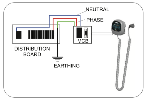
- Power requirement: 3KW, Single phase
- Wire thickness: 4sq mm for 25 meters, 6sq mm up to 100 meters length
- Power requirement: 3KW, Single phase
SAFETY: The power source should have MCB & proper earthing.
9 STEERING AND BRAKES
9.1 Power Steering
Your vehicle is equipped with power steering. The power steering system will give you good vehicle response and increased ease of maneuverability in tight spaces. If for some reason the power assist is interrupted, it will provide mechanical steering capability to steer the vehicle. Under these conditions, you will observe a substantial increase in steering effort, especially at very low vehicle speeds and during parking maneuvers.
Upon initial start-up in cold weather, the power steering pump may produce noise for a short amount of time. This is due to the cold, thick fluid in the steering system. This noise should be considered normal, and it does not in any way damage the steering system.
Continued operation with reduced power steering performance
could pose a safety risk to yourself and others. Have the vehicle
serviced at specified intervals or whenever a power steering
problem is noticed.
When driving in rough/off roads, hold the steering wheel rim,
do not hold the wheel spokes. A sudden bump can jerk/ turn
the wheel and injure your hand. This may also lead to loss of
vehicle control.
Keep both hands on the steering wheel, with the thumbs resting on the outer wheel rim.
To help prevent damage to the power steering pump:
- Never hold the steering wheel to the extreme right or the extreme left for more than a few seconds when the vehicle is running
- Heavy or uneven steering efforts may be caused by low power steering pump fluid level. Check for low power steering pump fluid level before seeking service by an Authorized Mahindra Dealer
- Do not fill the power steering pump reservoir above the MAX mark on the reservoir, this may result in leaks from the reservoir
If the power steering system breaks down (or if the vehicle is turned OFF), you can still steer the vehicle manually, but it takes more effort.
If the steering wanders or pulls, check for:
- Under inflated tire(s) on any wheel(s)
- Uneven vehicle loading
- High crown in the centre of the road
- High crosswinds
- Wheels out of alignment
- Wheels out of balance
- Loose or worn suspension components
9.2 Brakes
Your vehicle is equipped with disc brakes in the front and drum brakes in the rear.
Disc brakes offer good braking capability and reduced stopping distance. Wet brake discs result in reduced braking efficiency. After a car wash or driving the vehicle through water, dab the brake pedal while driving to remove the film of water from the brake pads. Brake pads feature wear indicator. When the brake pad is worn, metallic squeal noise is heard indicating the pad wear. Have them replaced immediately.
Driving with wet brakes is dangerous. Stopping distance
increases considerably when braking.
Dry the brakes by driving at very slow speed and applying the
brakes lightly until the brake performance becomes normal.
Even if the power assist (vacuum assistance) is completely lost, the brakes will still work. The brake pedal would be much harder than normal and the vehicle stopping / braking distance will be longer than usual.
9.2.1 Parking on a Hill/Incline
If you have to park facing uphill, turn the front wheels away from the kerb. If you have to park facing downhill, turn the front wheels towards the kerb. Always ensure the vehicle is in Park mode and parking brake is engaged before leaving the vehicle.
9.2.2 Parking Brake
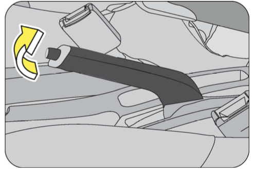
To apply the parking brake, pull the park brake lever up as firmly as possible. When the parking brake is applied with the ignition ON, the brake warning lamp in the instrument cluster illuminates. To release the parking brake, pull the parking brake lever up slightly, press the release button on the lever tip and lower the parking brake lever completely.
The brake warning lamp indicates only the parking brake status. It does not indicate the degree of brake application. Be sure the parking brake is firmly set when parked.
Be sure the parking brake is fully disengaged before driving off. Failure to do so can lead to brake problems due to excessive heating of the rear brakes.
- The parking brake should be adjusted as per recommended maintenance schedule
- Always apply the parking brake when leaving the vehicle. Failure to do so may allow the vehicle to roll and cause damage, hit a bystander resulting in personal injury.
- Leaving unattended children in a vehicle is dangerous for a number of reasons. Children should be warned not to touch the parking brake or the gear shift lever. Do not leave the key in the ignition. A child could move the vehicle leading to accidents
- The parking brake should always be applied when the driver is not in the vehicle.
Engaging the parking brake while the vehicle is in motion can cause the rear wheels to lock up. You could lose control of the vehicle and cause an accident.
9.3 Anti-Lock Braking System (ABS) (if equipped)
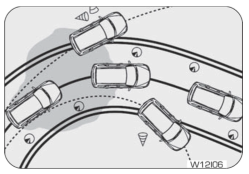
The Anti-lock Brake System (also called as ABS) is designed to help prevent lock-up of the wheels and stable stopping of vehicle during a sudden, panic emergency braking or braking on slippery road surfaces. The ABS system takes input from wheel speed sensors and brake pedal switch to control the brake fluid pressures at the wheels to avoid wheel lock-up. It allows vehicle to be steered during braking.
The minimum speed for ABS to function is 12 kmph. ABS is activated only during wheel lock conditions where ABS takes over and prevents wheel lock. During the ABS operation, a slight pulsation may be felt in the brake pedal to indicate ABS is active. You may also hear motor noise. It is recommended to hold the brake pedal firmly while the ABS is active rather than pumping the brake pedal.
Depressing the brake pedal on slippery road surfaces as on a manhole cover, a steel plate at a construction site, a joint in a bridge, etc. on a rainy day, tends to activate the anti-lock brake system. The ABS warning lamp lights up when you switch ON the ignition and should go out after a few seconds. If the ABS warning lamp does not go out or if it comes ON while driving, it means there is a fault in the ABS system. In both cases, the normal braking system remains efficient, exactly as on a vehicle without ABS.
The vehicle should be examined as soon as possible by an authorized Mahindra dealer. The Anti-lock brake system is not designed to shorten the stopping distance: Always drive at a moderate speed and maintain a safe distance from the vehicle in front of you. The stopping distance may be longer in the following cases:
- Driving on rough, gravel or snow covered roads.
- Driving with tyre chains installed.
- Driving over the steps such as the joints on the road.
- Driving on roads where the road surface is pitted or differences in surface height.
The ABS warning lamp lights up when you switch ON the ignition and should go out after a few seconds. If the ABS warning lamp does not go out or if it comes ON while driving, it means there is a fault in the ABS system. In both cases, the normal braking system remains efficient, exactly as on a vehicle without ABS. The vehicle should be examined as soon as possible by an authorized Mahindra dealer.
Do not overestimate the Anti-lock Brake System: Although the Anti-lock Brake System assists in providing vehicle control, it is still important to drive with all due care and maintain a moderate speed and safe distance from the vehicle in front of you. There are limits to the vehicle stability and effectiveness of steering wheel operation even with ABS active. If tyre grip performance exceeds its capability, or if hydroplaning occurs during high speed driving in the rain, the Anti-lock Brake System will not assist with vehicle control.
HEATING, VENTILATION AND AIR-CONDITIONING SYSTEM (HVAC)
10.1 Heating, Ventilation And Air-Conditioning System (HVAC)
The climate control system enables you to set the cabin at the desired comfortable condition by controlling airflow, air intake and temperature control. The HVAC system also helps in defrosting and defogging/de-misting the windshield and windows.
Multiple vents are provided for distributing the air, being force circulated by the HVAC blower, throughout the passenger compartment. Various ducts supply air from the HVAC unit to these vents having adjustable louvers.
To ensure sufficient air flow and hence adequate HVAC system performance, the air flow path should be kept free of obstructions. Keep the system’s air intake, located near the plenum appliqué, free of snow, leaves and other debris. Also keep the area in front of the air vents free of any obstruction inside the cabin.
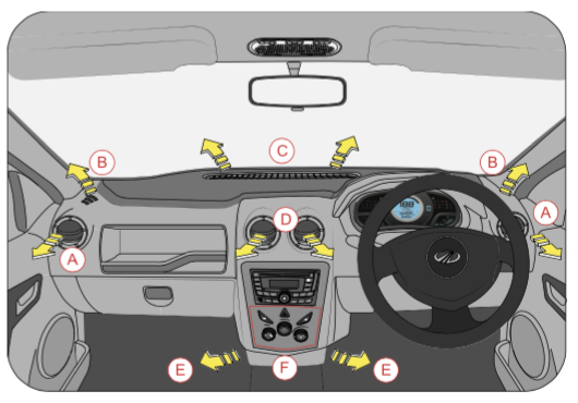
| A | Side Vents | D | Center Vents |
| B | Side Defrost Vents | E | Foot Vents |
| C | Windshield Defrost Vents | F | HVAC Controls |
10.3 Centre Vents/Side Vents
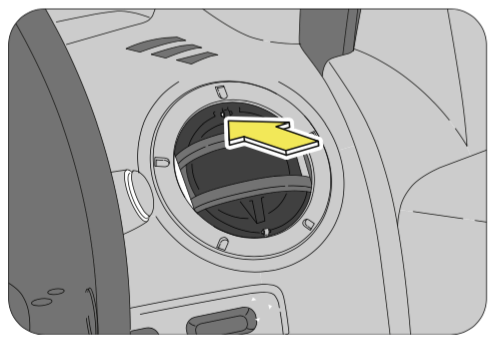
Two center vents are located on either side of the centre console. The two side vents are located one each at the left and right extreme ends of the instrument panel. Both the center and side vents provide air flow to the front seat passengers.
Press the louver on the vent to open the vent. You can direct the air flow as required by adjusting the louvers. The louvers can also be turned 360oto the required direction.
There are four defrost vents in your vehicle; two side defrost and two windshield defrost vents. The side defrost vents prevent the front windows from de-misting, whereas the windshield defrost vents help in clearing the mist from windshield.
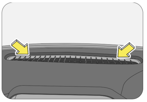
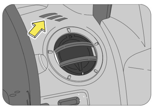
10.4 HVAC Controls
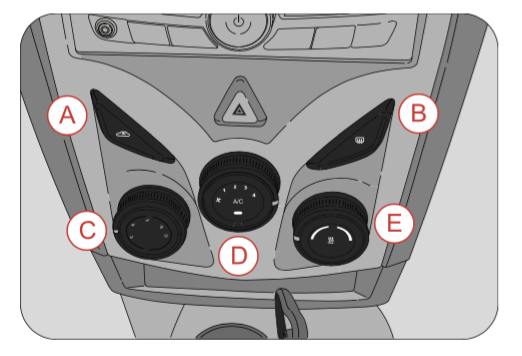
| A | Air Re-circulation Switch | D | Blower Speed Control & AC ON/OFF |
| B | Rear Windshield De-mister | E | Temperature Control |
| C | Air Distribution Control |
10.5 Air Distribution Control
Air distribution control allows you to select the below air flow patterns;
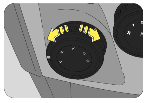
- Face Mode
- Face-Foot Mode
- Foot Mode
- Foot-Defrost Mode
- Defrost Mode
Rotate the control dial on the air distribution switch to adjust the air flow pattern as required.
When air distribution is set to “Defrost Mode”, the air intake is automatically changed to “Fresh Air Mode” and the LED is turned OFF. Once the air distribution is changed from “Defrost” to any other mode, the air intake is maintained in “Fresh Air Mode” until changed manually.
10.6 Temperature Control
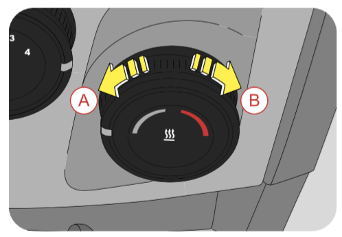
| A | Cool Air | B | Hot Air |
By operating the temperature control knob, temperature of air being discharged from various vents can be adjusted to the desired level. Based upon selected position of the temperature control dial, the desired discharged air temperature can be obtained.
When temperature knob is set in any intermediate position on the blue/cold side, the compressor turns ON/OFF at specific intervals to maintain the desired temperature. This is normal.
To turn the heater, keep the temperature knob position towards the “red” side and switch on the AC.
By rotating the dial counter-clockwise and setting it to the extreme left position, cool air is discharged. When the dial is rotated clockwise, the discharge air progressively starts getting warmer. By rotating the dial further in the clockwise direction and setting it to the extreme right position, hot air is discharged.
Blue strip/side represents cooling and red strip/side represents heating.
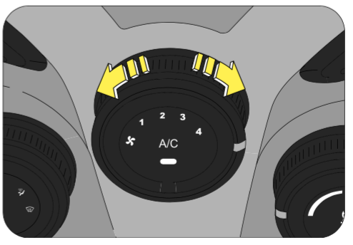
Blower force-circulates air through the HVAC unit and distributes it throughout the passenger compartment.
To increase the blower speed, rotate the control dial clockwise and to reduce the blower speed, rotate the dial counter clockwise.
To switch OFF the blower, rotate the dial to the extreme left in anticlockwise direction.
The compressor speed also varies with the blower position. Hence the cooling and noise in the cabin will vary accordingly.
10.8 Air Conditioner Control (AC ON)
This button is common for AC and heater, it turns ON the AC/ heater based on the temperature knob position. Adjust the temperature control dial as per the temperature requirement. LED on the button indicates the status. Push the button to turn ON/OFF the AC.
When the air conditioner is functioning, air gets cooled and dehumidified before being circulated inside the cabin. In hot weather conditions, it will take a slightly longer time to cool the interior as compared to cooler weather. Range of the vehicle will be relatively lower if the vehicle is being driven with the air conditioner.
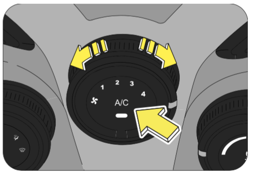
10.8.1 Re-circulation/Fresh Air Mode
Press the re-circulation mode button located in the HVAC control bezel, to toggle between fresh air and recirculation modes.
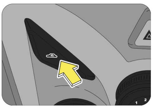
In the intake mode, the air from inside the passenger compartment will be sucked by the blower and utilized further to ventilate/cool/ heat the cabin.
For quick cabin cooling/heating or while driving through dusty/ polluted areas, re-circulation mode can be selected for short periods.
However, running the air conditioner in re-circulation mode for long will make cabin air too dry and oxygen level drops inside cabin turning the air stale. On the contrary, keeping air intake control in recirculation mode for long, with air conditioner switched OFF, will make cabin air too humid and are more likely to become foggy. Hence never drive in recirculation mode without the AC for long.
Never keep recirculation mode selected without the AC. Prolonged use of the HVAC system in recirculation mode without the AC may cause windshield/windows to mist/fog-up, impairing visibility which can lead to an accident, endangering you and others.
For faster cabin cooling or heating you can select re-circulated air intake mode. It is recommended to switch to fresh air mode occasionally to replenish the oxygen level inside the cabin. Also blower speed and temperature control knob can be re-adjusted as desired.
If your vehicle was parked in the hot sun with all the windows closed, drive the vehicle with windows open for the first few minutes. This will help in venting the hot interior air out and allow the air conditioner to cool the cabin quickly.
10.8.2 Front Windshield Defogging/De-misting
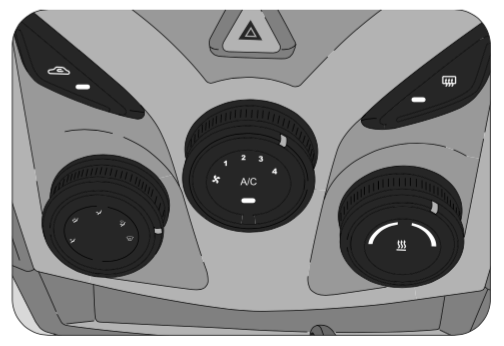
Set the air distribution control to defrost mode and set the temperature to hot. When defrost mode is chosen, the air intake is automatically set to fresh air mode.
Air is discharged through the windshield defroster vents and side defroster vents. The defogger heats the front windshield clearing the fog/ frost. Switch OFF the defogger/defrost mode as soon as the fog/frost is cleared.
10.8.3 Rear Windshield Defogging/De-misting (if equipped)
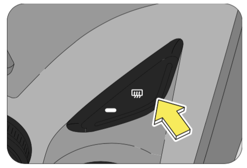
- If SOC is less than 10%, AC will switch off to save energy for driving only
- For quickly defogging/de-misting/defrosting outside of windshield, it is advisable to operate the windshield wiper/ washer for few times intermittently.
- In freezing weather, warm the windshield with the defroster before using the windshield washer. Also use a washer fluid having anti-freezing properties. These will help prevent the washer fluid from freezing on your windshield.
- Dirty/contaminated windshield would make misting/ fogging- up worse. Always keep inside and outside of windshield clean.
- Reduced air flow because of clogged HVAC filter or any other obstructions in air flow path may lead to in-adequate defogging/ de-misting/defrosting performance. If air flow seems to have considerably reduced, get the filter cleaned or replaced immediately. Air flow path should be kept free of obstructions.
Your vehicle is equipped with a HVAC filter. If the AC performance is considerably low, it is recommended have the HVAC filter checked at the nearest Mahindra dealer.
Never operate HVAC system with the filter removed. This may result in premature failure of system components.
- The air conditioning system in this vehicle also supports cooling for the HV batteries.
- There are chances for AC switching on even if the AC switch is in OFF position. This is due to HV battery cooling requirement. This is applicable even during key OFF and charging modes.
- Sometimes even when cabin heater is requested, you may get cool air out of the vents. This is due to cooling request from the HV batteries. This condition will return back to user mode once the battery cooling requirement is met.
- Sometimes even when the AC switch is turned OFF, and only the blower is ON, you may still get cool air, this is due to cooling request from the HV batteries.
In all the above conditions, you have an option to turn OFF the blower till the battery requirement is met.
11 STARTING AND DRIVING THE VEHICLE
11.1 Safety Tips - Before Starting your Vehicle
11.1.1 General
- Before starting the vehicle, inspect the inside and outside of the vehicle and look for any damages, leaks, loose parts, foreign objects/debris. Contact an Authorized Mahindra Dealer if required.
- Before starting your journey, check the working of all safety devices/components especially brakes, steering, lamps, signals and tires. In case you suspect any system/devices not working properly contact Authorized Mahindra Dealer.
- Adjust the seat headrest, steering wheel and fasten the seat belt as described in this manual. Never perform any seat/ steering adjustments when the vehicle is in motion.
- Start the vehicle only when seated and belted in the driver's seat.
- Ensure that the rear view mirror and both the ORVM’s are adjusted for an unobstructed view of the road behind.
- Have someone observe and confirm normal operation of all exterior lamps while you work on the controls from the driver seat. Also, check functioning of all lamps in the instrument panel.
- Check for positive closing, latching, and locking of all doors, both from inside and outside.
- Check the area under vehicle after an overnight parking for power steering fluid, brake fluid or other fluid leaks. If leaks are observed, contact an Authorized Mahindra Dealer.
11.2 Pedals
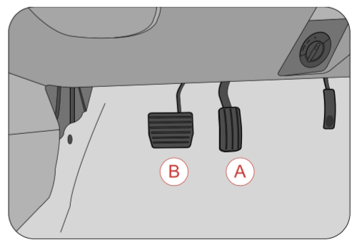
| A | Accelerator Pedal | B | Brake Pedal |
11.3 Transmission
The first few shifts on a new vehicle may be somewhat rough. This is a normal phenomenon, and precision shifts will develop within the initial few hundred kilometers of running.
11.3.1 Gear Lever
Gear lever enables you to choose your desired drive direction. This shift pattern is imprinted on the gear lever knob.
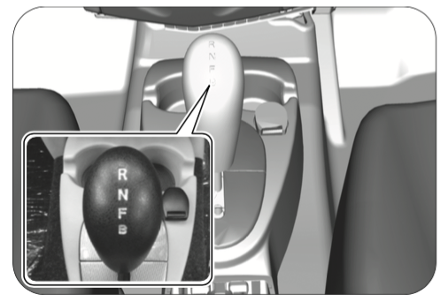
A gear indicator is integrated in the instrument cluster to aid in identifying the gear.
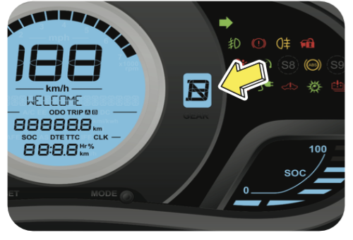
Press gear release button on the lever and then move lever from 'N' to 'F' mode. This is normal driving mode position to drive in forward direction (max speed is 86 kmph) and driving in this mode will give best drive range.
This position also enables you to drive in forward direction with quick acceleration & to overtake during driving.
It is always recommended to keep the brake pedal depressed in this position. Always park your car in ‘Neutral’ position before turning off STOP button.
Do not leave the vehicle with the gear shift lever in neutral position. Always engage manual parking brake before leaving the vehicle, to prevent any vehicle movement leading to possible injury to a by-stander or damage to vehicle.
This gear is to enable the vehicle to move in the reverse direction with beep and speed is limited to 20 Kmph. Press gear release button and move the gear shift lever into this position only after the vehicle has come to a complete stop.
11.4 Starting and Driving
Check energy level on SOC bar and digital SOC display. Ensure that there is enough charge for your immediate journey
Simple steps to get your car started & ready to drive:
- Turn off power supply and remove plug from wall socket.
- Unplug charge cable. Roll it & keep inside vehicle.
- Turn on Key
- Press Drive enable button (wait for LED to glow Orange colour)
- Pressing gear release button, select gear lever to desired driving position.
- Release parking brake, press accelerator pedal. Use only your right leg for applying accelerator & brake pedal.
- When you require a higher acceleration to overtake other vehicles or in up-hill climbing, move gear lever to ‘Boost’ [B] mode. In this mode you attain a much higher torque. The max. Speed is 86 kmph and it is possible for you to switch from Forward [F] mode to Boost [B] mode or vice-versa while car is in motion. However, for optimal driving range, you are advised to use Forward [F] mode.
- To reverse, make sure that your car is stationary. Then move gear lever to reverse [R] mode. Press accelerator gently and drive backward. In this mode, speed is electronically limited to 20 kmph approx. for safety reasons.
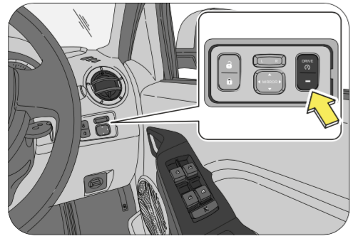
When charge level in your battery pack reduces to less than 10% SOC, vehicle energy monitoring system puts vehicle on “power save mode” where in car will drive in reduced power.
This is due to pre-programmed software in your vehicle’s Intelligent Energy Management System [IEMS] and Motor Controller. These components will monitor, as far as possible, that you never get stranded on the road due to insufficient energy in battery Pack. Digital SOC & SOC bar displays available energy and ‘distance to empty’ indicating your driving range from previous & present drive. As you cover distance, digital SOC & gauge bar will reduce continuously displaying possible drive range from remaining energy in battery pack.
Operate brake pedal and accelerator pedal with your right foot only.
While driving, if you remove your foot from accelerator pedal without pressing brake pedal, you will feel partial regenerative braking. This is normal and is attributed to vehicle’s regenerative braking that will re-charge batteries for an extra drive range.
Always ensure energy level is sufficient for proposed travel distance. Avoid driving below 1% State of Charge as vehicle might stop at any point of time from now. Find nearest charge point to charge your car.
11.5 Parking the Vehicle
- After stopping the vehicle, select Neutral (N) position (confirm by checking the gear indicator in the instrument cluster) while depressing the brake pedal.
- Apply the parking brake.
- Turn the key OFF.
- Check any warning message / chime during going out of vehicle.
11.6 REVive (if equipped)
In event of SOC is low (<10%) while in drive, you can activate reserve energy by activating “REVive”. This will allow you to get energy released from battery reserve to reach your destination or near charge point. ‘REVive’ feature to be used in emergency, hence use ‘REVive’ feature carefully by planning your daily travel.
User charges are applicable for REVive function.
11.7 Hill Hold and Restraint (if equipped)
This feature allows you stop your car on inclined roads for few seconds after pressing and holding brake for a second. It gives an added advantage to user for having good control while driving on an incline.
- Press & hold brake pedal for 1 second
- The car holds for 2 seconds & then slowly restrain backwards.
- To release car from hill hold or restrain, press accelerator or brake pedal.
11.8 Extending Your Driving Range
- Always make sure that you release parking brake completely before driving your car.
- Always drive car using right foot only.
- Always drive in Forward [F] mode to get optimum range out of your battery.
- Use B mode when you want to overtake or when you need additional boost.
- Pre cool your car cabin remotely (If equipped) by turning on air-condition when still plugged in for charge. This will ensure that battery will be 100% charge with cabin temperature preconditioned.
- Use air-condition with desired level of cooling set during drive. This will help in consuming less energy for cooling.
- By anticipating and applying gradual braking you will ensure car batteries will be recharged for extra range. Vehicle is assisted with electrical regenerative braking, also vacuum assisted brake for short stop.
11.9 Troubleshooting
| Problem | Possible Cause | Remedy | |
|---|---|---|---|
| 1 | Start button pressed, car not turning on with ‘UNPLUG CAR’ message. | Charge cable may not be removed from on board charge port. | Remove charging cable from car on board charge port. |
| 2 | Car not switching on with SHIFT GEAR TO ’N’ message on cluster. | Car may not be parked in neutral. | Switch on, move gear lever to neutral, authenticate and then shift to required mode. |
| 3 | ‘RELEASE ACC PEDAL’ fault on cluster and car will not drive. | Accelerator pedal may be depressed prior to ‘START’ button ON. | Release Accelerator pedal and ‘Authenticate’ car. |
| 4 | Temperature Light comes on while driving with ‘GO SLOW’ message on cluster. | EV drive system temperature may have reached max. Operating limit. | Drive your car slowly or stop and allow 15-20 minutes to cool. |
| 5 | Temperature Light comes on while driving with ‘STOP CAR’ message flashing on cluster. | EV drive system temperature may have exceeded maximum operating limit. | Park your car at safe place. Engage parking brake. Wait for ~ 15 minutes till temperature light goes off and start driving / charging again. |
| 6 | Car stopped in drive with ’DRIVE FAULT’ message on cluster with EV warning lamp ON. | Vehicle speed sensor failure or loose connection. | In the event of this, car will drive under reduced performance with mild jerks. Park vehicle to side |
| 7 | Car stopped in drive with ’CHARGE CAR’ message on cluster. | Charge level of battery has dropped to 0% SOC. | Charge your car or activate REVive if available. |
| 8 | Error message ‘TOPUP BRAKE FLUID’ and indication on cluster. | Brake fluid level may have gone low in master cylinder. | Top up brake fluid with recommended grade to maximum level. |
| 9 | Car not driving per mode & throttle demand with ‘GO SLOW’ message. | Possible fault in EV drive system. | Drive carefully and request assistance from your dealer. |
| 10 | Car not moving with ‘DRIVE FAULT’ message on cluster. | EV drive system having permanent faults. | Contact your dealer for assistance. |
| 11 | Central door lock not operating with ‘CHANGE KEY BATT’ message. | Remote key fob battery voltage may be low. | Replace key fob battery with recommended type. |
| 12 | Poor wiping action: (Wiper blade is not moving or is stuck on windscreen area.) | Blade improperly set / Windshield is dirty with oil / Wiper blade worn-out. | Adjust blade position / clean wind-shield properly / Replace with a new wiper blade. |
| 13 | Immobilizer activated. | Opening door manually with a key will activate anti-theft alarm. | Press ‘UNLOCK’ button in remote to deactivate. |
| 14 | Hard Steering. | Low or uneven tyre pressure. | Inflate to correct tyre pressure. |
| 15 | Vehicle pulls to one side while driving. | Low or uneven tyre pressure/ disturbed Wheel Alignment. | Inflate to correct tyre pressure / check wheel alignment at your nearest Authorised Service Centre |
| 16 | Steering Kickback: (While driving, you feel jerks and vibrations on steering wheel.) | Low or uneven tyre pressure. | Inflate to correct tyre pressure. |
| 17 | Hard or Rough ride: (When you drive your car, you feel that ride is bumpy and rough.) | Excessive tyre pressure. | Deflate to correct tyre pressure. |
| 18 | Wheel Wobbling: (While you drive, wheels and / or steering shake.) | Incorrect wheel balancing and/or alignment. | Contact an Authorized Service Centre and get wheels checked for alignment and balancing. |
If any of problems mentioned here persists even after you have attempted remedial measures mentioned above, please contact Authorized Service Centre.
11.10 Do’s and Don’ts
| Do's | Don'ts |
|---|---|
| Accessories | |
| Only recommended accessories should be installed through Authorized Service Centre. | The customers should not install any electrical accessories. Unauthorized addition of electrical accessories can damage your vehicle and manufacturer warranty will become null and void. |
| Parking | |
| Always engage parking brake while parking your car. | Never leave the car without applying parking brake when parked. |
| Maintenance | |
| Use a damp cloth or a soft brush to clean interiors of your car. | Do not spray water inside your car as water can get inside electronic/electrical components. |
| Always keep your vehicle washed regularly to keep it to look new for a long time. | |
| Charging | |
| Inspect your charging cable periodically for any damage like cracks, cuts, exposed wire, etc. Replace if required. | Do not charge your car if external Power Source and / or on-board charge port are exposed to rain or water. |
| When charging process is over, first switch off power supply. Then remove charging cable from external Power Source and on-board charge port, in order. Roll up and store charging cable in its compartment behind rear seat. | Do not carry out charging procedure with wet hands. |
| Make sure that children are kept away from power source & on-board charge port during charging process. | Do not allow children or People having implanted medical electric devices near car while carrying out charging process. |
| When your car is not in use, keep it on charge. | |
| Allow battery Pack to charge completely whenever possible. | |
| Ensure proper earthing, over voltage protection, earth line circuit breaker has been provided to charging point. | |
| Service | |
| Car should be disconnected from power source before getting any services being carried out. | Do not charge car while washing or cleaning. |
| Press service disconnect switch provided under bonnet before getting any services being carried out. | Do not use / spray inside vehicle while washing / cleaning. |
| Get your car serviced at specified intervals as per recommended maintenance schedule in user manuals. | |
| Check Brake Fluid Level at least once a month. Have it topped up if low brake fluid light starts flashing. | |
| Driving | |
| Always ensure right charge for right distance. Check SOC level on gauge before commencing a journey. | Do not undertake drive when SOC level is very low. Driving at this stage might reduce life of battery pack. |
| Always wear seat belt while driving. | Avoid sudden acceleration and hard turns. This will consume more energy and thereby affecting driving range. |
| Adhere to maximum payload is 300 kg for better acceleration, driving range and comfort. | Do not use accelerator pedal to hold car on an incline. |
| As far as possible, drive in Forward [F] mode. This will optimize your driving range. Accelerate moderately always. | |
| While driving during night, switch off head lights while idle at a traffic signal. This will help in conservation of energy & optimize driving range. | |
| Always maintain recommended tyre pressure for optimizing driving range, comfort and increased tyre life. | |
Battery box is installed under the vehicle, so take special care during driving over the humps and unpaved roads.
Your vehicle needs special attention in below situations: Please contact your dealer service person for support.
- Charge Light stays on even after charge cable is removed or it does not come on when car is put on charge.
- EV warning light stays on in drive. (This can be due to temporary faults, check message on cluster & drive carefully).
- Service Light stays on in drive.
- IP cluster Light stays on after start up switch is turned off.
- Temperature Light solid after start up switch is turned on.
- Parking Light & Low brake fluid light stays on after parking brake is disengaged and there is adequate brake fluid.
12 WHEELS AND TIRES
12.1 Tire Information
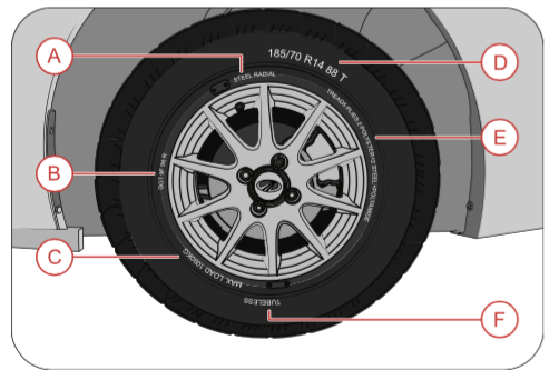
| A | RADIAL TIRES OR BIAS-PLY TIRE |
| B | DOT INFORMATION |
| C | MAX LOAD LIMIT |
| D | TIRE SIZE |
| E | TIRE COMPOSITION |
| F | “TUBELESS” OR “TUBE TYPE” |
12.2 Tire Rating
Your vehicle is originally equipped with tires supplied by a reputable manufacturer. If you ever have any questions regarding your tires, please refer to literature supplied by the tire manufacturer, or to the separate tire warranty provided by the tire manufacturer. You may also contact Mahindra directly, or the tire manufacturer.
The tire rating of your vehicle is;
- 185/70 R14 88T
Tire rating is explained as below;
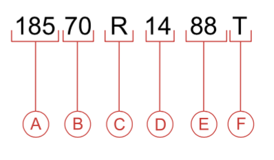
(A):185 (Three-digit number): This number gives the width in millimeters of the tire from sidewall edge to sidewall edge. This is called as “Section Width”.
(B):70 (Two-digit number): This number, known as the aspect ratio, gives the tires ratio of height to section width.
(C): R This is the Tire Construction Code. The “R” stands for Radial.
(D):14 (Two-digit number):This number is the wheel or rim diameter in inches.
(E):88(Two or three digit number):This number is the tire’s load index. It is a measurement of how much weight each tire can support.
(F): T Tire speed rating or speed symbol. Never drive the vehicle faster than the tire speed rating. The speed rating denotes the speed at which a tire is designed to be driven for extended periods of time under a standard condition of load and inflation pressure.
12.2.1 Speed Rating
| SPEED SYMBOL | MAX SPEED CAPABILITY | SPEED SYMBOL | MAX SPEED CAPABILITY |
|---|---|---|---|
| KM/HR | KM/HR | ||
| L | 120 | T | 190 |
| M | 130 | U | 200 |
| N | 140 | H | 210 |
| P | 150 | V | 240 |
| Q | 160 | W | 270 |
| R | 170 | Y | 300 |
| S | 180 | Z | 240+ |
12.3 Tire Label (Vehicle Placard)
Tire Label (Vehicle Placard) is located on the front passenger side inner B-pillar. This placard tells you important information about tire size designed for your vehicle, and the laden/unladen tire inflation pressures for the front & rear tires.
Never overload your vehicle. Overloading can cause tire failure, affect vehicle handling, and increase your stopping distance, resulting in an accident and/or personal injury.
Improper inflated tires can adversely affect vehicle handling or can fail unexpectedly, resulting in an accident and/or personal injury.
12.4 Tire Pressure
Proper tire inflation pressure is essential to the safe and satisfactory operation of your vehicle. Three primary areas are affected by improper tire pressure;
- Safety
- Economy
- Ride Comfort and Vehicle Stability
Proper tire inflation contributes to a comfortable and safe ride. Overinflating produces a jarring and uncomfortable ride. Both underinflation and overinflation affect the stability of the vehicle and can produce a feeling of sluggish response or over responsiveness in the steering. Unequal tire pressures can cause erratic and unpredictable steering response or may cause the vehicle to drift left or right.
Improper inflation pressures can cause uneven wear patterns to develop across the tire tread. These abnormal wear patterns will reduce tread life resulting in a need for earlier tire replacement. Under inflation also increases tire rolling resistance and may result in lesser range.
The proper cold tire inflation pressure is listed in the Tire Label (Vehicle Placard), located on the front passenger side inner Bpillar.
12.4.1 Inspection and Adjustment Procedure
The tire pressure should be checked and adjusted, as well as inspected for signs of tire wear or visible damage, at least once a month. Use a good quality pressure gauge to check tire pressure. Do not make a visual judgement when determining proper inflation. Radial tires may look properly inflated even when they are underinflated. At the same time, each tire should be inspected for signs of tire wear or visible damage.
Inflation pressures specified on the placard are always cold tire inflation pressures. Cold tire inflation pressure is defined as the tire pressure after the vehicle has not been driven for at least three hours, or driven less than 1 km after a three-hour period. Check tire pressures more often if subject to a wide range of outdoor temperatures, as tire pressures vary with temperature changes. Tire pressures change by approximately 1 psi (7 kPa) per 7°C of air temperature change. Keep this in mind when checking tire pressure inside a garage, especially in the winter.
When it was new, the spare tire in your vehicle was fully inflated. However, a spare tire can lose pressure over time. In order to avoid being stranded, check the spare tire air pressure frequently.
12.4.2 Inflating Your Tires
Safe operation of your vehicle requires that your tires are properly inflated. Remember that a tire can lose up to half of its air pressure without appearing flat.
At least once a month or before long trips, inspect each tire and check the tire pressure with a tire gauge (including spare tire). Inflate all tires to the recommended inflation pressure.
Under-inflation is the most common cause of tire failures and may result in severe tire cracking, tread separation or “blowout”, with unexpected loss of vehicle control and increased risk of injury. Under-inflation increases sidewall flexing and rolling resistance, resulting in heat buildup and internal damage to the tire. It also may result in unnecessary tire stress, irregular wear, loss of vehicle control and accidents.
Always inflate your tires to the recommended pressure even if it is less than the maximum inflation pressure information found on the tire. The recommended tire inflation pressure is found on the Tire Label which is located on the front passenger side inner B-pillar. Failure to follow the tire pressure recommendations can cause uneven tread wear patterns and adversely affect the way your vehicle handles.
If you overfill the tire, release air by pushing the metal stem in the center of the valve. Then recheck the pressure.
After inspecting or adjusting the tire pressure, always reinstall the valve stem cap (if equipped). This will prevent moisture and dirt from entering the valve stem, which could damage the stem, resulting in an unexpected loss of tire pressure, an accident and/or personal injury.
12.4.3 Radial Ply Tires
Combining radial ply tires with other types of tires on your vehicle will cause your vehicle to handle poorly, resulting in an accident and/or personal injury. Always use radial tires in sets of four. Never combine them with other types of tires.
Cuts and punctures in radial tires are repairable only in the tread area because of sidewall flexing. Consult your authorized dealer for radial tire repairs.
12.4.4 Life of Tire
The service life of a tire is dependent upon various factors including but not limited to;
- Driving style
- Tire pressure
- Distance driven
Tires and the spare tire should be replaced after six years, regardless of the remaining tread. Failure to follow this warning can result in sudden and unexpected tire failure, leading to an accident and/or personal injury.
Replacing original tires with tires of a different size may result in false speedometer and odometer readings.
12.5 Tire Rotation Recommendations
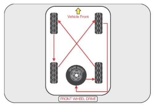
Tires on the front and rear axles of vehicles operate at different loads and perform different steering, handling, and braking functions. For these reasons, they wear at unequal rates and develop irregular wear patterns.
Rotation will increase tread life, help to maintain mud, snow, and wet traction levels, and contribute to a smooth, quiet ride. Follow the recommended tire rotation frequency for your type of driving.
It is recommended rotating the tires as per the “Maintenance Schedule”.
The suggested rotation method is the “forward-cross” shown in the diagram. The benefits of rotation are especially worthwhile with aggressive tread designs such as those on On/Off-road type tires.
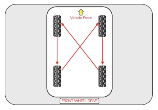
Rotation will increase tread life, help to maintain mud, snow, and wet traction levels, and contribute to a smooth, quiet ride. Follow the recommended tire rotation frequency for your type of driving. More frequent rotation is permissible if desired. The reasons for any rapid or unusual wear should be corrected prior to rotation being performed.
12.5.1 Changing a Flat Tire
Refer to “If you have a Flat Tire” section in the general chapter for details.
12.5.2 Wheel Tightness
When you change a wheel, remove all rust and dirt at all locations where the wheel contacts the wheel hub. Use a scraper or wire brush to be sure that you remove all rust and dirt. A loose wheel could have damaged or elongated the holes in the rim, or damaged the rim/hub assembly. If any of the wheel studs or nuts are damaged, contact the nearest Authorized Mahindra Dealer.
Always tighten the nuts in a crisscross sequence. Never use oil or grease on your wheel studs or nuts.
Never over tighten the nuts on the wheel stud. You could damage the stud or the nut.
Torque tighten the wheel nuts to the specified value at the nearest Authorized Mahindra Workshop.
The tyres fitted in this vehicle meet the requirements of BIS and they comply with the requirements under the Central Motor Vehicles Rules (CMVR) 1989.
13 MAINTENANCE
13.1 General Owners Information
Your vehicle has been designed for fewer maintenance requirements with longer service intervals to save both your time and money. However, each regular maintenance, as well as day-today care is more important to ensure a smooth, trouble free, safe and economical operation.
It is the owner's responsibility to make sure the specified maintenance, including general maintenance service is performed.
Where to go for service?
Mahindra technicians are well trained specialists and are kept up to date with the latest service information through technical bulletins, service tips and in dealership training programs. They learn to work on Mahindra vehicles before they work on your vehicle, rather than while they are working on it.
You can be confident that your Mahindra dealer's service department does the best job to meet the maintenance requirements on your vehicle reliably and economically.
Get the most from your vehicle with routine maintenance
Routine maintenance is the best way to help ensure you get the performance, dependability, long life and better resale value you expect from your vehicle. This is exactly why we've put together this Maintenance Section. It outlines the services required to properly maintain your vehicle and when they should be performed. The focus is on maintaining your vehicle while it's running great, which goes a long way towards preventing major repairs and expenses later.
Here are a few suggestions to help you get started on routine maintenance:
- Familiarize yourself with your vehicle by going through your Owner's Manual
- Take a few minutes to review this Maintenance Section
- Consult with your Authorized Mahindra Dealer for all your vehicle's needs
13.1.1 Need Assistance?
It is recommended talking to an Authorized Mahindra Dealer service manager first. Most matters can be resolved with this process. If for some reason you are still not satisfied, talk to the general manager or owner of the dealership.
If an Authorized Mahindra Dealership is unable to resolve the concern, you may contact any Mahindra Customer Care executive. They would need the following information:
Owner's name and address, owner's telephone number (home and office), Authorized Dealership name, Vehicle Identification Number (VIN), vehicle delivery date and mileage.
13.1.2 Protect your Warranty
Routine maintenance is not only the best way to help keep your vehicle performing as intended, it's also the best way to protect your warranty. Failure to perform scheduled maintenance specified will invalidate warranty coverage on parts affected by the lack of maintenance. We can't stress enough how important it is to keep records of all maintenance. Damage or failures due to neglect or lack of proper maintenance are not covered under warranty.
It's important to document the maintenance of your vehicle. For your convenience to maintain records of service, the scheduled maintenance coupons are provided in the service coupon booklet. Every time you bring your vehicle in for scheduled maintenance, be sure to present this booklet and certify the work. Also record the date of service and mileage at the time of service. This will make record keeping easy and, should your vehicle ever require warranty coverage, you will have all the documentation to show you've properly maintained it.
13.1.3 Maintenance Interval
Mahindra establishes recommended maintenance intervals based upon engineering testing to determine the most appropriate mileage to perform the various maintenance services. This protects your vehicle at the lowest overall cost to you. Mahindra recommends that you do not deviate from the maintenance schedules presented in this Maintenance Schedule.
The hood release lever is located in the driver side foot well area, below the instrument panel. To open the hood, follow the steps below;
- Pull the hood release lever below the driver side instrument panel to release the hood.
- Lift the hood a little to access the safety latch holding the hood striker. This safety latch is located below the hood at the center
- Move the safety latch to the left and lift the hood to as much height as required
- Release the unhinged end of the stay rod from its lock clip and insert its unhinged end in the slot below the already lifted hood
- Allow the hood to be supported by the stay rod
- Do not apply any undue force on the bonnet when it is supported by the stay rod
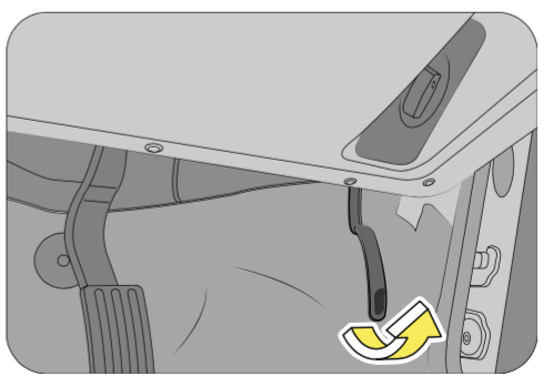
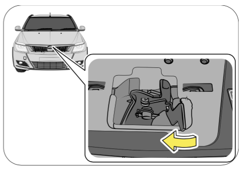
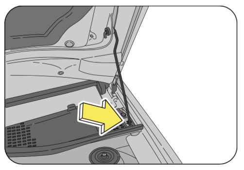
- Always double check to be sure that the hood is firmly latched before driving away. If it is not latched properly, the hood could open while the vehicle is being driven, causing a total loss of visibility, resulting in an accident.
- Do not move the vehicle with the hood in raised position, as vision is obstructed.
13.3 Closing the Hood
- Remove the stay rod supporting the hood by slightly lifting the hood
- Slowly lower the hood, while swinging down the stay rod and locking its unhinged end in the lock clip
- Bring the hood just a few inches above its fully closed position
- Now, release the hood and allow it to fall by its own weight. This ensures that safety latch firmly locks the hood in its fully closed position
13.4 Service Disconnect Switch (SDS)
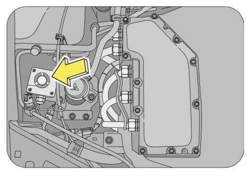
Your vehicle has an automatic functionality like cooling fan for the HV batteries which could come ON at any time irrespective of the key position. So a service disconnect switch has been provided under bonnet near vacuum switch to disconnect the HV Li-Ion batteries from the vehicle system while working on the vehicle. Press the switch down once and wait for few minutes for the system to complete the disconnect.
Before performing any electrical maintenance work on the vehicle such as the battery replacement, fuses or bulb replacement located inside EBox compartment, ensure the following:
Check the HV cable voltage before attempting to open or touch the EBox connections. The voltage should be < 10V
- The charge connector is removed from the vehicle
- Key is not inserted in the vehicle
- Service disconnect switch is pressed
- Pull the service disconnect switch up
- Plug a charger or use the wake up switch provided on EBox near to LV battery
13.5 EBox Compartment
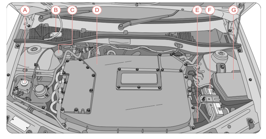
| A | Service Disconnect Switch | E | Power Steering Fluid Reservoir |
| B | Windshield Washer Fluid Reservoir | F | Auxiliary Battery |
| C | Brake Fluid Reservoir | G | vehicle Compartment Fuse Box |
| D | E-Box |
Maintenance is classified as below;
- General Maintenance
- Scheduled Maintenance
13.6 General Maintenance
Listed below are the general maintenance items that should be performed frequently. In addition to checking the items listed below, if you notice any unusual noise, fluid leakages, smell or vibration, you should investigate the cause or take your vehicle to your Authorized Mahindra Dealer or a qualified service shop immediately.
- Front windshield washer fluid level
- Battery condition
- Brake fluid level
- Power steering fluid level
- Fluid leaks
- Hoses, joints and pipes for any abnormalities
- Lights
- Warning lamps
- Windshield wipe and wash
- Steering wheel
- Seats
- Seat belts
- Accelerator pedal
- Brake pedal
- Brakes
- Parking brake
- Gear lever shift mechanism
- Lamps
- Fluid leaks
- Doors and hood latches
- Tire inflation pressure
- Tire surface/thread and wheel nuts
13.7 In the EBox Compartment
13.7.1 Checking/Topping Brake Fluid
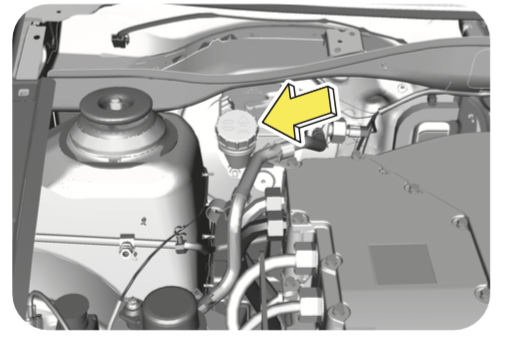
The brake system fluid is supplied from the brake reservoir.
The brake fluid level will drop slowly as the brakes wear, and will rise when the brake components are replaced. Fluid levels between the “MIN” and “MAX” lines are within the normal operating range; there is no need to add fluid. If the fluid levels are below the “MIN” mark, the performance of the systems could be compromised; the brake operation could be spongy.
Top-up the recommended brake fluid till the “MAX” mark or contact an Authorized Mahindra Dealer immediately.
Carefully clean the cap on the reservoir before you remove it and be sure no debris fall in the reservoir. Do not keep the reservoir open for longer than necessary to add brake fluid.
Use only brake fluid that meets Mahindra specifications. Refer to ‘Lubricant and Capacities’ section.
Draining or changing of brake fluid should always be done by an Authorized Mahindra dealer.
13.7.2 Checking/Topping Power Steering Fluid
Check the power steering fluid level at the defined service intervals.
The power steering reservoir is located in the LHS behind the left head lamp/front bumper. It is recommended that the power steering fluid top-up/change be done by an Authorized Mahindra Dealer.
The fluid level should be checked if a leak is suspected, abnormal noises are apparent, and/or the system is not functioning as anticipated. Coordinate inspection efforts through an Authorized Mahindra Dealer.
Driving vehicle with power steering fluid below minimum mark will damage steering system.
Use only recommended power steering fluid. Do not use other types of power steering fluids which may damage the power steering system.
13.7.3 Windshield Washer Fluid Top-up
Top up the front windshield washer reservoirs as and when required. The front windshield washer is located below the wipers in the EBox bay.
In very cold weather conditions, fill the reservoir with washer fluid premixed with anti-freeze.
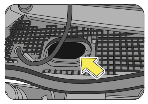
If you operate your vehicle in temperatures below 4.5ºC, use washer fluid with anti-freeze protection. Failure to use washer fluid with anti-freeze protection in cold weather could result in impaired windshield vision and increase the risk of injury or accident.
13.7.4 Checking the Wiper Blades
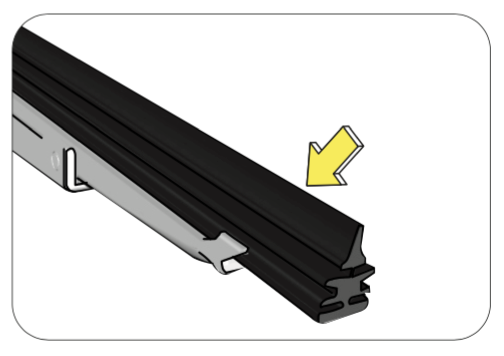
Lift the wiper arm from its position. Expose the blade lip for inspection. Clean the wiper blade lips with water applied with a soft sponge. If the wiper blade is not wiping the glass satisfactorily or is worn-out, cut, cracked or bulging get it replaced at an Authorized Mahindra Dealer.
13.7.5 Changing the Wiper Blade
- Lift the arm and position the wiper blade at right angles to the wiper arm
- Press the retaining clip in the opposite direction, disengage the wiper blade and pull it off the arm
- Hold the end of the rubber and pull until the tabs are free of the metal support
- Carefully insert the new blade rubber. Then install the blade assembly in the reverse order of removal
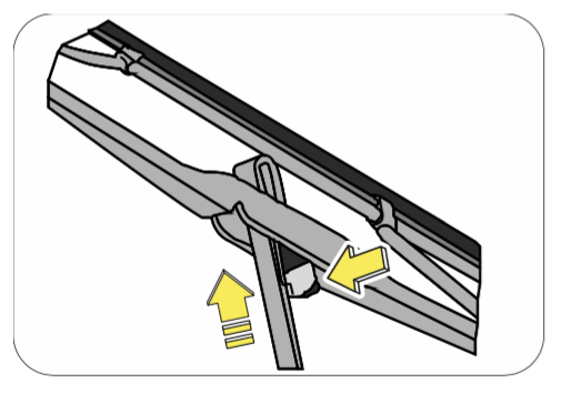
To prevent damage to the windshield, don’t let the wiper arm slap down on to it.
13.8 Appearance Care and Protection
13.8.1 Washing the Exterior
- Wash your vehicle regularly with cool or lukewarm water and a neutral pH soap
- Never use strong household detergents or soap, such as dish washing or laundry liquid. These products can discolor and spot painted surfaces
- Never wash a vehicle that is ‘hot to touch’ or during exposure to strong, direct sunlight
- Always use a clean sponge or car wash mitt with plenty of water for best results
- Dry the vehicle with a chamois or soft terry cloth towel in order to eliminate water spotting
- It is important to wash the vehicle regularly during the winter months, as dirt and road salt are difficult to remove and cause damage to the vehicle
Use only approved products to clean plastic parts. These products are available with your authorized dealer. You can use these cleaners;
- For routine cleaning of plastic parts
- For tar or grease spots
- For plastic head lamp lenses
13.8.2 EBox Compartment
Do not wash the EBox compartment with high pressure water.
13.8.3 Windows and Wiper Blades
The front/rear windshield, side windows and the wiper blades should be cleaned regularly. If the wipers do not wipe properly, substances on the vehicle's glass or the wiper blades may be the cause. These may include hot wax treatments used by commercial car washes, water repellent coatings, tree sap, or other organic contamination; these contaminants may cause squeaking or chatter noise from the blades, and streaking and smearing of the windshield.
To clean these items follow these tips;
- The windshield, rear windows and side windows may be cleaned with a non-abrasive cleaner such as Clear Spray Glass Cleaner, available at your Authorized Mahindra Dealer.
- The wiper blades can be cleaned with alcohol or Premium Windshield Washer Concentrate, available at your Authorized Mahindra Dealer. This washer fluid contains a special solution in addition to alcohol which helps remove the hot wax deposited on the wiper blade and windshield. Be sure to replace wiper blades when they appear worn or do not function properly.
- Do not use abrasives, as they may cause scratches.
If you cannot remove those streaks after cleaning with the glass cleaner or if the wipers chatter and move in a jerky motion, clean the outer surface of the windshield and the wiper blades using a sponge or soft cloth with a neutral detergent or mild-abrasive cleaning solution. After cleaning, rinse the windshield and wiper blades with clean water. The windshield is clean if beads do not form when you rinse the windshield with water.
Do not use sharp objects, such as a razor blade, to remove decals, as it may cause damage to the glass or rear windshield heater grid lines (if equipped).
13.8.4 Instrument Panel/Interior Trim and Cluster Lens
Do not use chemical solvents or strong detergents when cleaning the steering wheel or instrument panel.
Clean the instrument panel, interior trim areas and cluster lens with a clean and damp white cotton cloth, then with a clean and dry white cotton cloth; you may also use Dash and Vinyl Cleaner on the instrument panel and interior trim areas.
- Avoid cleaners or polishes that increase the gloss of the upper portion of the instrument panel. The dull finish in this area helps protect the driver from undesirable windshield reflection
- Do not use household or glass cleaners as these may damage the finish of the instrument panel, interior trim and cluster lens
If a staining liquid like coffee/juice has been spilled on the instrument panel or on the interior trim surfaces, clean as follows;
- Wipe up spilled liquid using a clean white cotton cloth
- Apply Vinyl Cleaner to the wiped area and spread around evenly
- Apply cleaner to a clean white cotton cloth and press the cloth onto the soiled area and allow this to set in at room temperature for 30 minutes
- Remove the soaked cloth, and if it is not soiled badly, use this cloth to clean the area with a rubbing motion for 60 seconds
- Following this, wipe area dry with a clean white cotton cloth
13.8.5 Interior Maintenance
For fabric, carpets, cloth seats, safety belts and seats:
- Remove dust and loose dirt with a vacuum cleaner
- Remove light stains and soil with carpet and upholstery cleaner
- If grease or tar is present on the material, spot-clean the area first with a stain remover
- Do not use household cleaning products or glass cleaners, which can stain and discolor the fabric and affect the flame retardant abilities of the seat materials
- Do not use cleaning solvents, bleach or dye on the vehicle's safety belts, as these actions may weaken the belt webbing.
If the vehicle is not used for more than 1 week enable “Vacation mode” and save battery from idle discharge.
Operation of Vacation mode — Mobile App (if equipped) is required to activate vacation mode
- Car will charge or discharge till SOC reaches to 50% at start date / time and maintains at 50%.
- On end date / time, car come out from vacation mode and charge to 100% SOC and then onwards if not used it will be on trickle charge to maintain energy level.
- If car is charged 100%, at start date /time, car battery will discharge till 50% and stays in vacation mode.
- If SOC is less than 50%, vacation mode gets activated at start date / time and stays in vacation mode with same SOC.
13.10 Bulb Replacement
13.10.1 Head Lamp Bulb Replacement
The head lamp bulb can be replaced without removing the head lamp assembly from the vehicle. The head lamp assembly has been removed here for illustration purpose only.
To replace the head lamp bulb;
- Ensure ignition is switched OFF
- Remove the bulb assembly with connector from the head lamp by unlocking the wire clamp
- Detach the bulb assembly from the wiring connector near to the head lamp
- Insert the connector into the new bulb (of the same wattage), and follow the reverse procedure to assemble the bulb assembly in the headlight assembly
- Clamp the bulb assembly by wire clamp properly
Do not touch the new bulb with your fingers. Oil contamination will severely shorten bulb life. If the bulb comes in contact with any oily surface, clean the bulb with rubbing alcohol.
To avoid burning yourself, do not replace the light bulbs when they are hot. Halogen bulbs have pressurized gas inside and are to be handled with special care. Mishandling it may cause the bulb to burst or shatter. Hold the bulb with its metal/plastic holder/base and do not touch the glass part with bare hands.
Using bulbs with units of higher output capacity/wattage is illegal and may damage your vehicle’s electrical system.
Replacement bulbs must meet the specification of originally fitted bulbs.
13.11 Scheduled Maintenance
The scheduled maintenance jobs listed in the ‘Scheduled Maintenance Chart’ are those required to be carried out at regular predetermined intervals.
To make sure that your vehicle runs efficiently all the time, follow the maintenance schedule. The service interval for the scheduled maintenance is determined by the odometer reading. Take your vehicle to an Authorized Mahindra Service Station only. Trained technicians and genuine Mahindra parts at Mahindra Authorized service stations are best for your vehicle. They will perform all the scheduled maintenance jobs reliably and economically. Inadequate, incomplete and insufficient servicing may result in problems.
The owner should retain records/documents that proper maintenance has been performed as prescribed.
13.12 Maintenance Schedule Chart
| eVERITO | |||||||
|---|---|---|---|---|---|---|---|
| Description | Change Interval | Free Services | Paid Services | ||||
| 3000 | 20000 | 40000 | 60000 | 80000 | 100000 | ||
| A = Adjust as Necessary I = Inspect and correct/replace if necessary R = Replace C = Clean | |||||||
| Transmission | |||||||
| Transmission Oil | Replace at Every 20000 Km | R | R | R | R | R | R |
| Axles, Wheels and Tyres | |||||||
| Front bearing play | Inspect at Every 20000 Km | I | I | I | I | I | |
| Driveshaft Rubber Boots | Inspect at Every 20000 Km | I | I | I | I | I | |
| Tyre rotation* | Every 20,000 Kms | ||||||
| Wheel alignment* | INSPECT IF ABNORMAL CONDITIONS ARE NOTICED OR 40000KMS, WHICHEVER IS EARLIER | ||||||
| Brakes and Clutch | |||||||
| Brake pads/Calipers | Inspect at Every 20000 Km | I | I | I | I | I | |
| Brake fluid B | Replace every 40000 kms or 2 years | I | I | R | I | R | I |
| Brake Drum & Lining | Inspect at Every 20000 Km | I | I | I | I | I | |
| Parking Brake | Inspect at Every Service | I | I | I | I | I | I |
| Suspension | |||||||
| Front & Rear Suspension | Inspect at Every Service | I | I | I | I | I | I |
| Steering | |||||||
| Power Steering Fluid - Level & Leak | Inspect at Every Service | I | I | I | I | I | I |
| Electricals | |||||||
| Auxiliary Battery voltage/condition | Replace at Every 20000 Km | I | I | I | I | I | |
| All Lights, Warning Lamps, Horns, Wipers & Washers | Inspect at Every Service | I | I | I | I | I | I |
| HVAC | |||||||
| Check the system for leaks & Recharge if required* | Once in every two years | ||||||
| Particle Filter | Replace at Every 20000 KM or earlier under severe dusty operating conditions | R | R | R | R | R | |
| Battery cooling filter | Replace at Every 20000 Km | R | R | R | R | R | |
| Water Drain | Inspect at Every 20000 Km | I | I | I | I | I | |
| Final Inspection | |||||||
| Tyre Pressure | Inspect at Every Service | I | I | I | I | I | I |
| Check and ensure normal working of vehicle using diagnostic equipment | Inspect at Every Service | I | I | I | I | I | I |
| Check Battery Box under the vehicle | Inspect at Every Service | I | I | I | I | I | I |
| Check all HV cables for looseness, cuts, wear & tear | Inspect at Every Service | I | I | I | I | I | I |
| Road Test | Inspect at Every Service | I | I | I | I | I | I |
| B — Change brake fluid every 40000 km or every 2 years whichever earlier | |||||||
| *On chargeable basis | |||||||
| Lubricants and Capacities | ||||
|---|---|---|---|---|
| System | Lubricant | Capacity | Specification | Remarks |
| Transmission | KLUBERG | 600 +/- 25 ml | Semi Synthetic Oil | Brand specific. If any other brand is used, oil change interval has to be reduced to 10,000 km. if oil meets min. of API GL-4 SAE 75W-90 spec. |
| Power Steering | “ELF REANULTMATIC D2” | Maintain between MIN & MAX | Brand Specific & no other brand should be used | |
| Brake | MAHINDRA “MAXIMILE DOT 4” | Maintain between MIN & MAX | Brake Fluid Meeting SAE J1703; FMVSS No.116 DOT 4 or IS 8654 Type-2 Specification | |
| Refrigerant | R134a (AC Gas) | 1170 +/- 25 gms | ||
| Compressor Oil ”FVC68D from IDEMITSU” | 290 ml | |||